background image

– 8 –

HT-CN400DVW/HT-CN400DVA/HT-CN500DVW/HT-CN500DVA

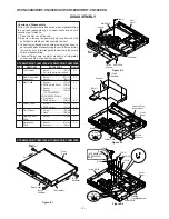
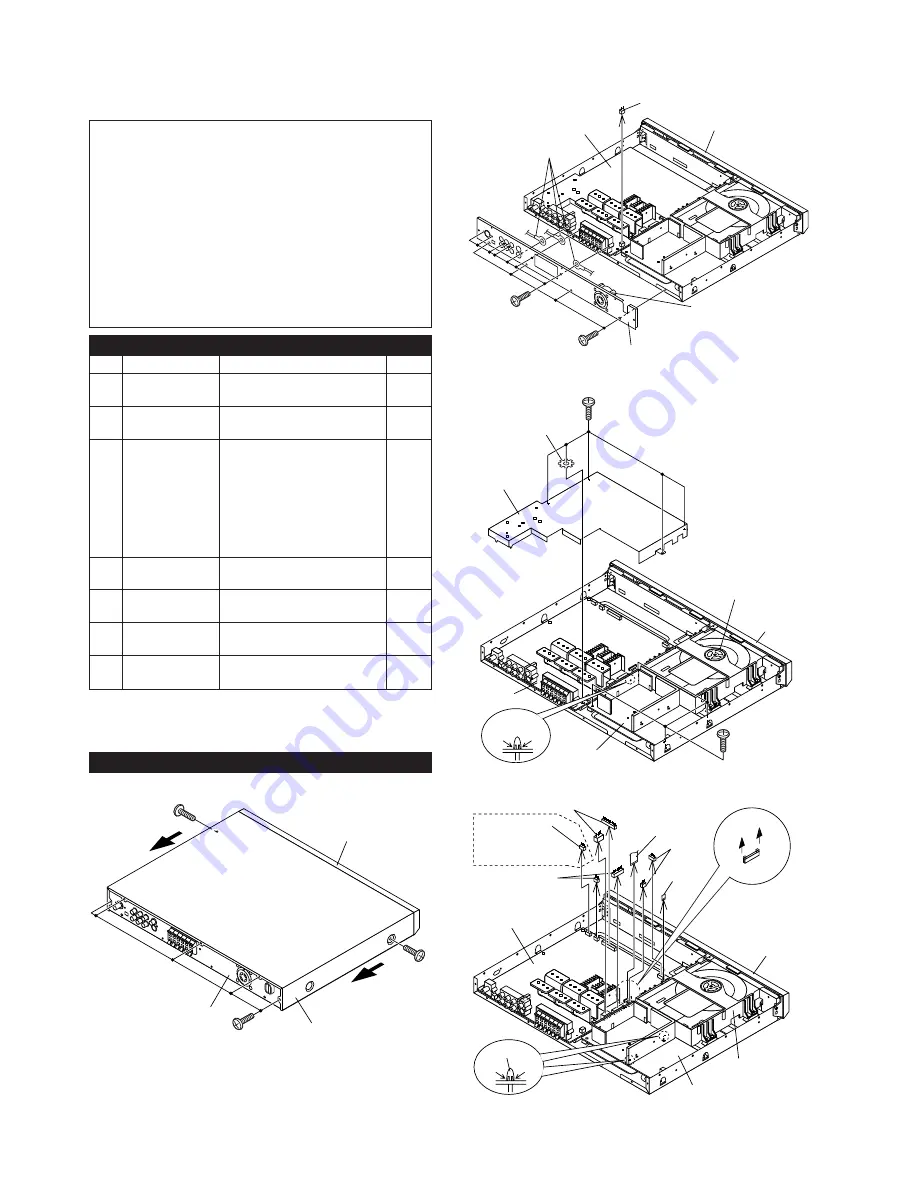
1

Top Cabinet

1. Screw ...................... (A1) x7

8-1

2. Pull to the arrow direction.

2

Rear Panel with

1. Screw .................... (B1) x11

8-2

Fan Motor

2. Socket ..................... (B2) x1

3

Main PWB

1. Screw ...................... (C1) x5

8-3

2. PWB Shield Cover .. (C2) x1
3. Socket ..................... (C3) x6

8-4

4. Socket ..................... (C4) x1
    (HT-CN400DVW/
HT-CN500DVW Only)
5. Flat Cable ............... (C5) x2
6. PWB Holder ...........  (C6) x1

8-3

4

Power PWB

1. Screw ...................... (D1) x4

8-3

4. PWB Holder ...........  (D1) x2

8-4

5

Front Panel

1. Screw ...................... (E1) x8

9-1

2. Hook ........................ (E2) x3

6

Display/Switch

1. Screw ....................... (F1) x9

9-2

PWB

7

Earphones

1. Screw ...................... (G1) x1

9-2

PWB

2. Bracket .................... (G2) x1

DISASSEMBLY

Figure 8-3

STEP

REMOVAL

PROCEDURE

FIGURE

Figure 8-2

HT-CN400DVW/HT-CN400DVA/HT-CN500DVW/HT-CN500DVA

Caution on Disassembly
Follow the below-mentioned notes when disassembling
the unit and reassembling it, to keep it safe and ensure
excellent performance:
1. Take dvd disc out of the unit.
2. Be sure to remove the power supply plug from the wall

outlet before starting to disassemble the unit.

3. Take off nylon bands or wire holders where they need to

be removed when disassembling the unit. After servicing
the unit, be sure to rearrange the leads where they were
before disassembling.

4. Take sufficient care on static electricity of integrated

circuits and other circuits when servicing.

HT-CN400DVW/HT-CN400DVA/HT-CN500DVW/HT-CN500DVA

Pull

Pull

(A1)x5
ø3x6mm

(A1)x1
ø3x6mm

(A1)x1
ø3x6mm

Rear Panel

Top Cabinet

Front
Panel

Figure 8-1

(D1)x4
ø3x8mm

(C1)x5
ø3x8mm

(C2)x1

Washer

Front
Panel

Loading Tray
Mechanism

Main PWB

Power PWB

Push

Push

(C6)x4

Figure 8-4

(B1)x4
ø3x6mm

(B1)x7
ø3x8mm

Rear Panel

Fan Motor

Main PWB

Front
Panel

Lug Wire

(B2)x1

(C3)x2

(C4)x1

(HT-CN400DVW/
HT-CN500DVW
Only)

(C5)x1

(C5)x1

(C3)x2

(C3)x2

Front
Panel

Main PWB

Power PWB

Loading
Tray Mechanism

(D2)x2

Push

Push

Summary of Contents for HT-CN400DVA

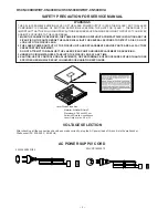
Page 1: ...WR surround speakers and CP CN400WSW subwoofer HOME THEATER WITH DVD MODEL HT CN400DVA HT CN400DVA Home Theater with DVD consisting of HT CN400DVA mainunit CP CN400F frontspeakers CP CN400C centerspeaker CP CN400R surround speakers and CP CN400SW subwoofer HOME THEATER WITH DVD MODEL HT CN500DVW HT CN500DVW Home Theater with DVD consisting of HT CN500DVW main unit CP CN500WF front speakers CP CN50...

Page 2: ...HE LASER BEAM 1 WHEN THE CABINET IS REMOVED THE POWER IS TURNED ON WITHOUT A COMPACT DISC IN POSITION AND THE PICKUP IS ON THE OUTER EDGE THE LASER WILL LIGHT FOR SEVERAL SECONDS TO DETECT A DISC DO NOT LOOK INTO THE PICKUP LENS 2 THE LASER POWER OUTPUT OF THE PICKUP UNIT AND REPLACEMENT SERVICE PARTS ARE ALL FACTORY PRESET BEFORE SHIPMENT DO NOT ATTEMPT TO READJUST THE LASER PICKUP UNIT DURING RE...

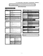
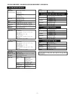
Page 3: ...rizontal resolution 500 lines S N ratio 70 dB Audio signal Frequency character istics Linear PCM DVD 20 Hz to 20 kHz sampling rate 48 kHz 20 Hz to 20 kHz sampling rate 96 kHz CD 20 Hz to 20 kHz S N ratio CD 94 dB 1 kHz Dynamic range Linear PCM DVD 95 dB CD 94 dB Total harmonic distor tion ratio 0 01 maximum Frequency range FM 88 108 MHz AM 531 1 620 kHz Type Full range speaker system magnetic shie...

Page 4: ...mber 4 ALL SVCD VCD audio CD CD R CD RW MP3 Video signal Horizontal resolution 500 lines S N ratio 70 dB Audio signal Frequency character istics Linear PCM DVD 20 Hz to 20 kHz sampling rate 48 kHz 20 Hz to 20 kHz sampling rate 96 kHz CD 20 Hz to 20 kHz S N ratio CD 94 dB 1 kHz Dynamic range Linear PCM DVD 95 dB CD 94 dB Total harmonic distor tion ratio 0 01 maximum Frequency range FM 87 5 108 MHz ...

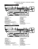
Page 5: ...tre Speaker Indicator 5 Subwoofer Indicator 3 Right Front Speaker Indicator 6 Right Surround Speaker Indicator Main unit front panel 1 On Stand by Button 2 Disc Tray 3 VDisc Tray Open Close Button 4 Remote Sensor 5 Play or Pause Button 6 Stop Button 7 Power Stand by Indicator 8 Function Button 9 Speaker Level Mode Button 10 Headphone Socket 11 Chapter track Skip Down or Tuning Down Button 12 Volum...

Page 6: ...lect Button 17 Return Button 18 Zoom Button 19 Echo Level Up and Down Buttons 20 Mute Button 21 On Stand by Button 22 Language Select Button 23 Display Button 24 FM Stereo Mono Select Button 25 Enter Button 26 Sleep Button 27 Play or Pause Button 28 Stop Button 29 Chapter track Skip Up or Tuning Up Button 30 Chapter track Skip Down or Tuning Down Button 31 Volume Up and Down or Speaker Level Adjus...

Page 7: ...on 27 Stop Button 28 Chapter track Skip Up or Tuning Up Button 29 Chapter track Skip Down or Tuning Down Button 30 Volume Up and Down or Speaker Level Adjust Buttons 31 Direct Number Buttons 32 Frame Advance Button 33 A B Repeat Button 34 NTSC PAL Select Button 35 Repeat Play Button 36 Audio Select Button PRESET ADJ VOL 9 8 7 6 5 4 0 10 3 2 1 ENTER SLEEP ST MO TUNING DISPLAY LANGUAGE MUTE PROG MEN...

Page 8: ...t safe and ensure excellent performance 1 Take dvd disc out of the unit 2 Be sure to remove the power supply plug from the wall outlet before starting to disassemble the unit 3 Take off nylon bands or wire holders where they need to be removed when disassembling the unit After servicing the unit be sure to rearrange the leads where they were before disassembling 4 Take sufficient care on static el...

Page 9: ... ø3x8mm G2 x1 F1 x3 ø3x8mm Front Panel Display PWB Earphones PWB Switch PWB STEP REMOVAL PROCEDURE FIGURE CP CN400WF CP CN400WC CP CN400WR CP CN400AF CP CN400C CP CN400R CP CN500WF CP CN500WC CP CN500WR CP CN500F CP CN500C CP CN500R Speaker Box A1 x1 Front Panel A2 x4 ø3 5x8mm Figure 9 3 B1 x4 ø3x8mm Speaker Front Panel 1 Speaker 1 Net Frame Ass y A1 x1 9 5 2 Screw A2 x4 STEP REMOVAL PROCEDURE FIG...

Page 10: ... region code If no press Enter button in five seconds then the region code remain original status 4 How to select OSD Language Sequency A Door close and no disc B Press and hold R C Volume up button C Then Press R C Subtitle button D OSD show last setting OSD language English France German Italian Spanish E Then use button to select language that you want and its sequence F For example default lan...

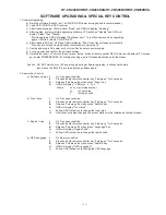
Page 11: ...ion DO NOT disturb or cut off power supply during software upgrading it will cause the data lost Hence the flash IC have to be burned software again 2 Special Key Control a Software version i On Tray open condition ii Press and hold remote controller key Volume up for 2 seconds iii Release Volume up key then press Zoom key iv OSD will display VER xxxx x yy z Where xxxx xis Version number yy is Tun...

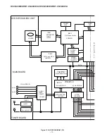
Page 12: ...CT D µ T FILTER FL FR C SL SR SUB I O PORT E XPAND AUX1 AUX2 FL FR C SL SR SUB TUNER 74LS374 3 CD4052 DATA LOADER MAIN BOARD M D D M W P 2CH AUDIO A D JRC4558 3 AUDIO BUFFER JRC4558 74LS157 Digital Audio Select 2CH AUDIO A D FLASH 8M SDRAM 256K I O PORT 74HC32 74HC14 DVD Servo RF IC LA9703W DVD MOTOR Drive IC LA6560 DVD MECHANISM UNIT TUNER BOARD IC801 IC802 IC803 IC110 ...

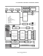
Page 13: ...E VOLUME PT2259 DDX 2100 2 CVBS S VIDEO FR FL C SL SR SPEAKER OUT OUTPUT POWER BOARD KEY ARRAY VFD MPEG II Decoder DOLBY DIGITAL Decoder DOLBY PROG LOGIC Decoder MP3 Decoder WMA Decoder Progressive Scan DIGITAL OUT OPTICAL COAXIAL FL FR C SL SR SU B L R DOWNMIXING JRC4558 PHONEAMP TP5228 L R POWER AMPLIFIER SUB SUB FR FL C SL SR SUB Bass management 6CH Volume Control Bass and Treble Control EEPROM...

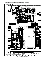
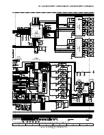
Page 14: ...C33 RST 24 10UF 0 1 111 25 VCC33E LA4 LA5 LA6 LA7 LA8 LA9 LA10 LA11 LA12 LA13 LA14 LA15 LA16 LA17 LA18 LA19 LA20 LA21 RESET LOE LCS0 LCS1 LCS2 LCS3 LD0 LD1 LD2 LD3 LD4 LD5 LD6 LD7 LD8 LD9 LD10 LD11 LD12 LD13 LD14 LD15 LWRLL LWRHL LA0 LA1 LA2 LA3 DCI_REQ HCLK HDACK DCI_ERR HD 0 7 HCLK HDACK DCI_REQ HD 0 7 DCI_ERR DCI_FDS DCI_FDS TDMFS TDMCLK TDMDR EAUX40 TDMDR TDMCLK TDMFS EAUX40 GU RESB FGO HIRQB ...

Page 15: ... VCCQ VCC VSS VCCQ DQ8 DQ9 VSSQ DQ10 DQ11 VCCQ DQ12 DQ13 VSSQ DQ14 DQ15 VSS VCC VSS A11 A10 A0 A1 A2 A3 A4 A5 A6 A7 A8 A9 MA0 MA1 MA2 MA3 MA6 MA4 MA7 MA5 MA11 MA9 MA10 MA8 35 22 23 24 25 26 29 30 31 32 33 34 2 4 5 7 8 10 11 13 42 44 45 47 48 50 51 53 DB0 DB1 DB2 DB3 DB4 DB5 DB6 DB7 DB8 DB9 DB10 DB11 DB12 DB13 DB14 DB15 1 3 9 14 43 49 27 VCC33 600 VC33 C144 C150 0 1 6 12 28 46 52 41 54 R A 6 5 10UF...

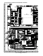
Page 16: ...VSS VSS VSS VSS VSS VSS VSS VSS VSS VSS VSS VSS VSS 129 8 17 26 34 43 52 60 67 76 84 91 98 103 120 138 147 156 163 171 177 184 192 200 208 SPDIF SEL_PLL3 41 NC APLL 48 SPDIFO 4 7K XIN XOUT CLK AUX0 AUX1 AUX2 AUX3 AUX4 AUX5 AUX6 AUX7 DB0 DB1 DB2 DB3 DB4 DB5 DB6 DB7 DB8 DB9 DB10 DB11 DB12 DB13 DB14 DB15 DMA0 DMA1 DMA2 DMA3 DMA4 DMA5 DMA6 DMA7 DMA8 DMA9 DMA10 DMA11 DQM DSCK DCS0 DCAS DSCK DOE DWE DRA...

Page 17: ... 0 01 1K 10UF 0 1 10UF 6 7 5 8 RC4558D 1K 5 6K 4 7K 332 0 01 0 01 1K 10UF 0 1 1K 22K 4 7K 150P 0 01 0 01 1K 10UF 2 4 3 RC4558D 0 1 10UF 10UF C A SUB A TU5V 5V 4 7K 2SA812 10K 100UF 2SC1623 TU12V 12V 4 7K 2SA812 10K 2SC1623 100UF SYR RDS DATA TU CE TU DI TU CL YU DO SDB TU5V TU12V TU L TU R 470 470 75 OHM VDAC L105 2 4µF CVBS1 47PF 6 5 360K 360K 56K 47K 68K 68K 8 7 RC4558D 0 1 10UF 0 1 6 7 5 8 15K ...

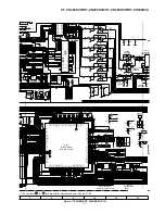
Page 18: ...16 39 20 21 36 40 DQML WE CAS RAS CS NC CKE CLK DQMH NC BA0 BA1 4Mx16 SDRAM 9ns VCC DQ0 DQ1 VSSQ DQ2 DQ3 VCCQ DQ4 DQ5 VSSQ DQ6 DQ7 VCCQ VCC VSS VCCQ DQ8 DQ9 VSSQ DQ10 DQ11 VCCQ DQ12 DQ13 VSSQ DQ14 DQ15 VSS VCC VSS A11 A10 A0 A1 A2 A3 A4 A5 A6 A7 A8 A9 MA0 MA1 MA2 MA3 MA6 MA4 MA7 MA5 MA11 MA9 MA10 MA8 35 22 23 24 25 26 29 30 31 32 33 34 2 4 5 7 8 10 11 13 42 44 45 47 48 50 51 53 DB0 DB1 DB2 DB3 DB4...

Page 19: ...2K 8 2K 100P 100P 8 2K 3 4 8 0 0056 0 0056 6 8K 6 8K 6 8K 6 8K 6 2K 6 2K 6 8K 6 8K 6 8K 6 8K 6 8K 6 8K S B S A LMUTE 1N4148 PRE L PRE R PRE SL PRE SR PRE C PRE SUB LINE MUTE PRE SUB PRE C PRE SR PRE SL PRE R PRE L AUX1 AUX0 LINE MUTE MUTE BASS STO DVD AUX0 AUX1 IR VFDCLK VFDCE VFD DA EARDEC MUTE BASS STO DVD IR VFD DA VFDCLK VFDCE EARDEC 5 6 9 8 2K 100P 100P 0 1 0 001 VGND AGND 0 1 0 1 0 001 0 001...

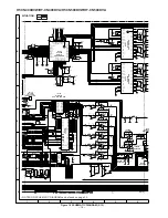
Page 20: ...2 4 3 1 0 1 4RC558D 10UF SR A 6 5 8 RC4558D 1K 22K 4 7K 150P 0 01 0 01 1K 10UF 0 1 10UF 6 7 5 8 RC4558D 1K 5 6K 4 7K 332 0 01 0 01 1K 10UF 0 1 1K 22K 4 7K 150P 0 01 0 01 1K 10UF 2 4 3 RC4558D 0 1 10UF 10UF C A SUB A TU5V 5V 4 7K 2SA812 10K 100UF 2SC1623 TU12V 12V 4 7K 2SA812 10K 2SC1623 100UF SYR RDS DATA TU CE TU DI TU CL YU DO SDB TU5V TU12V TU L TU R 470 470 75 OHM VDAC L105 2 4µF CVBS1 47PF 6 ...

Page 21: ...8 PRE L PRE R PRE SL PRE SR PRE C PRE SUB LINE MUTE PRE SUB PRE C PRE SR PRE SL PRE R PRE L AUX1 AUX0 LINE MUTE MUTE BASS STO DVD AUX0 AUX1 IR VFDCLK VFDCE VFD DA EARDEC MUTE BASS STO DVD IR VFD DA VFDCLK VFDCE EARDEC 5 6 9 8 2K 100P 100P 0 1 0 001 VGND AGND 0 1 0 1 0 001 0 001 0 001 0 001 0 001 VGND AGND AGND YG PBR CVBS1 600 600 600 1 3 4 5 6 47PF 47PF 47PF VGND 7 8 RCA SVIDEO OK_DA LRCK BICK AM...

Page 22: ... STAND BY LD301 AC1 AC2 24V LED3 POW B5V VFD_SDA VFD_SCL 5V IR VFD_DATA VFD_CLK VFD_STB RB303 CN609 TO MAIN PWB P19 11 6 1 2 3 4 C301 0 001 C302 0 001 C303 0 001 R306 100K R307 100K Q301 2SC1623 SN201 SENSOR 1 2 3 JK301 R301 22K R302 1K R303 1K ZD301 6V HT CN400DVW HT CN500DVW ONLY R308 100 C306 100UF C308 100 50 C304 0 1 C307 100UF C305 0 1 R311 1 R309 1 R310 1 R315 10K R320 560 C309 220 R313 4 7...

Page 23: ...24 25 26 OSC2 SW2 SW3 R C DATA SCL SDA CLK STB K1 K2 K3 K4 VDD SG1 KS1 SG2 KS2 SG3 KS3 SG4 KS4 SG5 KS5 SG6 KS6 SG7 KS7 SG8 KS8 SG9 KS9 SG10 KS10 SG11 KS11 SG12 SG13 SG14 SG15 SG16 SG17 GR12 SG18 GR11 VDD VEE SG19 GR10 SG20 GR9 GR8 GR7 GR6 GR5 GR4 GR3 GR2 GR1 VDD PCON LED4 LED3 LED2 LED1 GND OSC1 IC301 VDTR6311A FL DRIVER 1 2 3 4 5 6 7 8 9 10 11 12 13 XL301 455 zHz C310 150P C311 150P R316 10K R317...

Page 24: ...EMATIC DIAGRAM can be found on page 32 D901B BYV26D IC903 TOP249 POWER SWITCH AC POWER SU PPLY CORD AC 220 240 V 50 60 Hz 0 22 275V 0 22 275V 0 0022 250V 0 0022 250V 0 01 1KV 0 001 1KV IC905 NCP1050DIP SWITCH REGULATOR FAN MOTOR 225 2 1 RD BK CN601 TO MAIN PWB P21 9 F 0 0022 250V 0 0022 250V 0 0022 250V 0 1 0 1 470P 1KV 0 0022 ...

Page 25: ...TO MAIN PWB P21 11 G CN602 TO MAIN PWB P21 7 F CN606 TO MAIN PWB P21 10 F IC904 TL431 VOLTAGE REGULATOR 1 2 3 4 0 0022 250V 0 0022 250V C953B 0 001 1KV R926 33 1 2W FUSE Q903B 0 01 C609 0 0047 0 1 0 001 1KV 120 0 001 0 001 0 001 0 001 0 001 0 001 0 001 0 001 0 1 0 001 1V 0 001 1V 0 001 1V 0 001 50 0 001 50 0 001 50 0 001 Q904B 0 01 C951B 0 1 T903 ...

Reviews: