Sharp DX-361EM, Service Manual
The Sharp DX-361EM Service Manual is a comprehensive guide for operating and maintaining the DX-361EM model. Easily downloadable for free from our website, this manual provides step-by-step instructions and troubleshooting advice to ensure optimal performance of this high-quality product.
Share
Download


Reviews:
No comments
Related manuals for DX-361EM
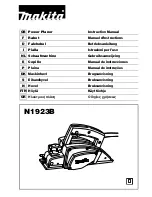
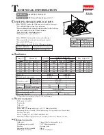
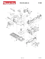
N1923B
Brand: Makita Pages: 60
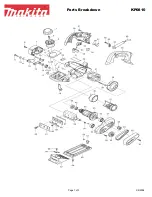
KP0810
Brand: Makita Pages: 11
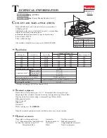
KP0810
Brand: Makita Pages: 3
KP0800
Brand: Makita Pages: 8
1912B
Brand: Makita Pages: 3
1911B
Brand: Makita Pages: 44
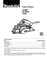
1900B
Brand: Makita Pages: 12
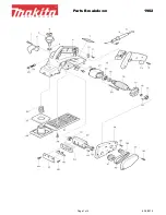
1902
Brand: Makita Pages: 2
KP312
Brand: Makita Pages: 3

VC6001
Brand: Marantz Pages: 2

AZ1005
Brand: Philips/Magnavox Pages: 2

92553
Brand: Central Forge Pages: 7

AZ8068 - Portable Radio Cass Rec
Brand: Magnavox Pages: 2

CH-DVD 635S
Brand: CyberHome Pages: 69

MW3837
Brand: GPX Pages: 8
iCONS
Brand: Jaguar King Pages: 54

BTP1800-254
Brand: Build Worker Pages: 16

KH 222
Brand: E-Bench Pages: 16


