1
2
3
4
5
6
7
8
9
10
11
12
13
14
15
16
17
18
19
20
A
B
C
D
E
F
G
H
I
J
DV-NC70/WDV-NC70X/RU
74~75
12-8. VCR MAIN (3) CIRCUIT SCHEMATIC DIAGRAM
Page 1: ... CH VCR DVD SELECTOR TIMER VCR DVD PLAY STOP AV 2 IN VIDEO L MONO AUDIO R OPERATE PLAY 2 Page 1 IMPORTANT SERVICE NOTES 2 2 FEATURES 3 3 SPECIFICATIONS 3 4 PART NAMES 5 5 MAINTENANCE CHECK ITEMS AND EXECUTION TIME 8 6 DISASSEMBLY METHOD 9 7 OPERATION OF PICKUP 13 8 ADJUSTMENT REPLACEMENT AND ASSEMBLY OF MECHANICAL UNITS 14 9 TEST MODE 37 10 TROUBLESHOOTING 40 11 BLOCK DIAGRAMS 54 12 SCHEMATIC DIAG...
Page 2: ...d the plug firmly when connecting or disconnecting the AC power cord Keep the AC power cord away from heating appliances Never put any heavy object on the AC power cord Do not attempt to repair or reconstruct the AC power cord in any way VARO AVATTAESSA OLET ALTTIINA LASERSÄTEILYLLE ÄLÄ TUIJOTA SÄTEESEEN ÄLÄKÄ KATSO SITÄ OPTISEN LAITTEEN LÄPI VARNING LASERSTRÅLNING NÄR DENNA DEL ÄR ÖPPNAD STIRRA E...
Page 3: ...quality digital sound 1 Manufactured under license from Dolby Laboratories Dolby and the double D symbol are trademarks of Dolby Laboratories 2 DTS and DTS Digital Surround are trademarks of Digital Theater Systems Inc 3 SPECIFICATIONS Signal system PAL NTSC INPUT OUTPUT JACKS DVD VCR shared output jacks VIDEO jack RCA Pin jack AUDIO jack RCA Pin jack DVD output jacks VIDEO jack S Video jack Compo...
Page 4: ...vel 1 Vp p 75Ω PB output level 0 525 Vp p 75Ω 75 colour PR output level 0 525 Vp p 75Ω 75 colour S video output Y output level 1 Vp p 75Ω C output level 0 3 Vp p 75Ω Audio output Output level 2 Vrms 1 kHz 0 dB Video signal horizontal resolution 500 lines S N ratio 60 dB Audio signal frequency characteristics For DVD linear PCM playback 4 Hz to 22 kHz 48 kHz sampling 4 Hz to 44 kHz 96 kHz sampling ...
Page 5: ... DVD Main Unit Front DVD Front Panel Display You can toggle between 1 and 2 by pressing the remote control unit s DISPLAY button LINE IN 2 4 PART NAMES VCR Main Unit Front OPEN CLOSE EJECT STOP REW REC CH VCR DVD SELECTOR TIMER VCR DVD PLAY STOP AV 2 IN VIDEO L MONO AUDIO R SEPVP D VCR L R OPERATE PLAY 2 VCR DVD SELECTOR OPERATE REC Clock Indicator Channel Indicator Tape Counter Indicator PLAY 2 F...
Page 6: ...VCR DVD VCR ANTENNA IN RF OUT LINE IN 1 AUDIO R L VIDEO AUDIO R L VIDEO LINE OUT 1 DIGITAL AUDIO AUDIO R L S VIDEO Y P R C R P B C B COMPONENT VCR AUDIO input jacks ANTENNA IN antenna or cable input VCR VIDEO input jack ANTENNA OUT DVD VCR shared AUDIO output jacks DVD Coaxial DIGITAL output jack DVD S VIDEO output jack DVD AUDIO output jacks DVD VCR shared VIDEO output jack COMPONENT VIDEO output...
Page 7: ... SELECTOR VCR MENU DVD SETUP TAPE SPEED ON SCREEN TITLE DVD MENU DISPLAY FUNCTION CONTROL PROG REPEAT CLEAR RETURN OPERATE TIMER ON OFF EJECT SET ENTER ZERO BACK SKIP SEARCH VCR DVD AM PM INPUT SELECT PAUSE STILL REC SLOW CH VCR DVD SKIP DPSS AUDIO OUTPUT VCR DVD COMBINATION ANGLE ON SCREEN OPERATE DISPLAY FUNCTION CONTROL RETURN TITLE CURSOR Number buttons REV STOP VCR DVD SELECTOR PROG REPEAT AN...
Page 8: ...y be easily damaged by electrostatic charges When handling the pickup take care so that the electrostatic charge is not generated 3 The semiconductor laser may be easily damaged by overcurrent Use the power supply unit which does not give any spike current when the power is turned on and off 4 Carefully remove the dust and dirt from the objective lens with the lens blower When handling the objecti...
Page 9: ...e the one hook 5 and tilt the PWB toward you to remove it 2 Release the one hook 6 and tilt the PWB toward you to remove it 4 Removing the DVD mechanism 1 Remove the four screws 7 to remove the DVD REINF angle 2 Remove the two screws 8 and two screws 9 3 Remove the two screws 0 to remove the Angle DVD 4 Remove the DVD Shield lower q 2 1 1 4 3 5 6 4 4 4 9 10 9 10 8 7 12 11 5 Remove the four screws ...
Page 10: ...ving the Cassette Housing Control VCR Mechanism 1 Remove the two screws r 2 Remove the one screw t 3 Remove the two screws y 6 Removing the Antenna Terminal Cover VCR Main PWB Unit 1 Remove the four screws u 2 Remove the two screws i 3 Remove the one screw o 7 Removing the Bottom Plate 1 Remove the one screw p ...
Page 11: ... AN Extension cable wire 9pin 130mm DVD Main CN3201 Power CN201 6 2 EXTENSION CABLE USE POINT ONE PLACE Extension Cable Diagram Power PWB CN201 Tuner CN3201 DVD Main PWB DVD Mechanism VCR Operation PWB DVD Operation PWB VCR Mechanism VCR Main PWB QCNW A361WJZZ 9 pin MPX SKEW PWB ...
Page 12: ...hassis 1 After setting the mechanism chassis to the angle state ground it to prevent the electrostatic discharge damage of the pickup 2 Remove the DVD Shield lower 40 refer to the illustration on page 112 3 Remove P Q from the DVD Main PWB Unit 27 Pickup Relay FFC 58 isn t removed refer to the illustration on page 112 4 Remove screws fixing the base chassis located at the back right and at front l...
Page 13: ... laser light even if the flowing current is slightly varied the projection light is detected with the monitor diode to control the laser light to be equally output Since the current varies on the monitor diode according to the intensity of the received light of the laser diode the drive current of the laser diode is reduced if the current of the monitor diode increases On the contrary the drive cu...
Page 14: ...ion Remarks JiGTG0090 CM 3 Torque Gauge Head JiGTH0006 AW JiGRH0002 BR JiGSG2000 BS JiGSG0300 BF 7 JiGADP003 BK Tension Gauge These Jigs are used for checking and adjusting the reel disk height When fixing any part to the threaded hole using resin with screw use the jig Specified torque 5 kg This cassette torque meter is used for check ing and adjusting the torque of take up for measuring tape bac...
Page 15: ...ation requires replacement Clean tape contact part with the specified cleaning liquid Clean tape contact area with the specified cleaning liquid Clean rubber and rubber contact area with the specified cleaning liquid Replace the roller of the cleaner when it wears down Just change the AHC roller assembly for new one Screen swaying Cassette not loaded or unloaded No tape running tape slack Tape sla...
Page 16: ...ss y 5 Open guide 6 Supply reel disk 7 Supply main brake 8 Take up main brake 9 Pinch drive cam 10 A C head ass y 11 Reverse guide lever ass y 12 Reel relay gear 13 Take up reel disk 14 Pinch roller lever ass y 15 Drum ass y 16 Loading motor block 17 Drum driver motor 18 Take up pole base ass y 26 Auto head cleaner ass y 17 15 26 11 5 9 14 12 8 16 13 4 6 2 7 3 1 18 10 ...
Page 17: ...V NC70X RU FUNCTION OF MAJOR MECHANICAL PARTS BOTTOM VIEW No Function No Function 19 Syncro Gear 20 Master cam 21 Capstan D D motor 22 Reel belt 23 Clutch lever 24 Limiter pulley ass y 25 Sifter 25 24 21 22 19 20 23 ...
Page 18: ...ial setting position install the cassette housing Conditions When mechanism and Main PWB have been installed 8 4 1 DISASSEMBLING THE MECHANISM 1 When removing the mechanism from the set Remove the two screws 1 which connecting mechanism and main frame Take out vertically the mechanism so that it does not damage the adjacent parts 2 Removing the mechanism and cassette housing Remove the two screws ...
Page 19: ... power supply to rotate the loading motor please remove unsolder at least one terminal wire If voltage applied to loading motor without disconnecting the terminal wire there is a possibility the capstan motor IC will damage Rotate the flange of worm gear by using thin stick CW Loading direction CCW Ejection direction Note Be careful not to damage the gear of worm gear and worm wheel gear It might ...
Page 20: ...OUSING CONTROL ASSEMBLY 1 Remove the full surface panel 2 Short circuit between TP803 and TP802 on VCR Operation PWB 3 Plug in the power cord 4 Turn off the power switch The pole bases move into U L position 5 Open the lid of a cassette tape by hand 6 Hold the lid with two pieces of vinyl tape 7 Set the cassette tape in the mechanism chassis 8 Stabilize the cassette tape with a weight 500g to prev...
Page 21: ...se does not adhere the brake surface 2 After reassembly check the video search rewind back tension see 8 12 and check the brake torque see 8 16 Height checking and adjustment Notes 1 Set the master plane with due care so that it does not contact the drum 2 When putting the master plane shift the reverse guide a little in the loading direction Care must be taken since excessive shift results in dam...
Page 22: ... After short circuiting between TP803 and TP802 pro vided at VCR Operation PWB plug in the power cord Setting 1 Set a torque gauge to zero on the scale Place it on the take up reel disk 2 Press the FF button 3 To calculate the remaining capacity of the play back mode slowly rotate the supply reel disk and then shift it into the forward mode Checking 1 Turn the torque gauge slowly one rotation ever...
Page 23: ...n it counterclockwise very slowly one rotation every 1 to 2 seconds and check that the torque is within the set value 14 1 3 5mN m 144 35gf cm Set value LP 6 9 mN m 70 gf cm Figure 8 9 Checking 1 Make sure that value is within the setting 6 9 mN m 70 gf cm 2 The winding up torque fluctuates due to variation of rotation torque of limiter pulley ass y Read the center value of fluctuation as setting ...
Page 24: ...ce the torque gauge on the take up reel disk and turn it counterclockwise very slowly one rotation every 2 to 3 seconds and check that the torque is within the set value 3 7 1 5mN m 38 15gf cm Pinch roller Tension gauge 900 1 200gf Capstan shaft Tension gauge adapter Figure 8 11 Torque gauge Take up reel disk Note Set the torque gauge securely on the take up reel disk If it is not secure the measu...
Page 25: ...ousing control Remove the cassette housing control assembly After short circuiting between TP803 and TP802 pro vided at VCR Operation PWB plug in the power cord Setting without cassette housing control 1 Turn off the power switch 2 Open the cassette torque meter and fix with tape 3 Set the cassette torque meter in loading state 4 Put the weight 500g on the cassette torque meter 5 Turn on the power...
Page 26: ...ue is within the setting clean the felt surface of reel disk supply take up brake lever check again the brake torque If value cannot be set within the setting yet replace the main brake ass y or main brake spring Figure 8 21 Figure 8 19 8 16 CHECKING THE BRAKE TORQUE Checking the brake torque at the supply side Figure 8 20 Remove the cassette housing control assembly After short circuiting between...
Page 27: ...solder the PWB fitted to the A C head Notes 1 When replacing never touch the head If you touched clean with the cleaning liquid 2 When removing the screw 3 take care so that the spring may out Figure 8 24 Notes 1 If the screw 1 is tighten tentatively too loose the azimuth and height of A C head may change when they are finally tightened Therefore care must be taken 2 After completion of A C head b...
Page 28: ...arly parallel 6 Unless the ATR signal waveform changes nearly parallel adjust the height of supply side and take up side guide roller so that the envelope waveform changes nearly parallel For ATR signal adjustment procedure refer to Figure 8 31 7 Turn the tilt screw to remove the tape crease at the fixing guide flange Playback the tape and check for tape crease at the fixing guide flange 1 If ther...
Page 29: ...tated in 8 17 Replacement 3 2 Connect the oscilloscope to the audio output termi nal 3 Using the alignment tape in which 1 kHz linear audio signal has been recorded adjust the height screw so as to get max audio output 4 Using the alignment tape in which 7 kHz linear audio signal has been recorded adjust the azimuth screw so as to get max audio output 5 The adjustment of 3 and 4 twice or three tim...
Page 30: ... 4 Adjust the playback switching point Refer to the electric adjustment method 5 Playback the self picture recorded tape and check the flatness of ATR signal waveform and sound Take up side Supply side Take up side Adjustment Supply side Supply side guide roller rotated in clockwise direction lowers guide roller to flatten ATR signal Take up side guide roller rotated in clockwise direction lowers ...
Page 31: ...m D D rotor ass y 5 After installation adjust the playback switching point for adjustment of servo circuit 8 20 REPLACEMENT OF THE CAPSTAN D D DIRECT DRIVE MOTOR Remove the mechanism from the set Removal Follow the order of indicated numbers 1 Unsolder loading motor wire and drum FFC 2 Remove the reel belt 1 3 Remove the three screws 2 Reassembly 1 Taking care so that the capstan shaft does not co...
Page 32: ...nt of Drum D D motor 2 Remove the drum earth brush ass y 2 3 Remove the upper and lower drum assembly from main chassis 1 4 Remove the drum FFC holder 3 Cares when replacing the drum 1 Be careful so that the drum earth brush is not lost 2 Do not touch directly the drum surface 3 Fit gently the screwdriver to the screws 4 Since the drum assembly is an extremely precise as sembly it must be handled ...
Page 33: ... below 2 Fix the sifter position setting part to the roading arm T position setting part as shown in figure 3 Make sure tension arm not run on the sifter as shown in figure c Loading arm T Sifter Insert point Loading arm T Loading arm S Phase matching Not run on the sifter Sifter Tension arm a c b Drum Capstan D D motor Bottom side of mechanism chassis a b ...
Page 34: ...OF LOADING MOTOR Removal Replacement Remove the loading motor and install the replacement loading motor as shown below Figure 8 41 Figure 8 39 2 The loading motor pressing in must be less than 196N 20 kgf Adjust the distance between motor and pulley to 6 95 mm Figure 8 39 1 Figure 8 40 0 2 0 15 E ring 6 95 mm A part Worm gear 0 0 15 Loading motor To press the motor in first receive it by portion A...
Page 35: ... lever spring and Holder R Figure 8 42 MSPRD0215AJFJ Proof lever spring fixing direction designated MSPRD0212AJFJ Take care not to damage this part Outside Outer Top Bottom Inner 2 Open lever Sensor Plate and Drive Lever to Frame R 3 Spring to Drive Arm R Figure 8 43 Figure 8 44 ...
Page 36: ... DV NC70X RU LANGF9661AJFW Top surface should be free from scratches or soil When assemble drive lever to frame R make sure the hole synchronize 4 Frame R Frame L Drive Arm R Drive Arm L and Upper Plate Figure 8 45 ...
Page 37: ...r Stop Key on the main unit Return to the initial test mode image Playback Key of the remote control is pushed for 7 times To 1 All FIP light up 40000000 00000000 OSD only Press 4 Key of the remote control Press 4 Key of the remote control NO DISC state F0 Key input Press Play Key and Stop Key for 5 seconds F0000000 00000000 LASER TEST DVD LD ON LASER TEST CD LD ON 1 Key input 3 Key input 1 Key in...
Page 38: ...nput Focus gain track gain adjustment STEP TEST GAIN STUDY ASMAX ENVPP FEPP ASAGC FEAGC FBAL0 FBAL1 TBAL0 TBAL1 FCGA0 FCGA1 TKGA0 TKGA1 In case of 2 layer DVD adjust the focus on track on focus balance adjustment and focus gain track gain adjustment STEP TEST DVD ID ASMAX ENVPP FEPP ASAGC FEAGC FBAL0 FBAL1 TBAL0 TBAL1 FCGA0 FCGA1 TKGA0 TKGA1 STEP TEST TRAY OPEN 2 Key input To 2 DVD operation STEP ...
Page 39: ...t figure Software for the renewal is started more 2 A power source is put with pushing DVD s own Playback Key and Halt Key at the same time It keeps pushing it for 3 seconds 3 When Y is inputted in accordance with the personal computer display and date transfer indication is shown and renewal process is started normally when Enter Key is pushed 4 When renewal is completed normally it becomes POWER...
Page 40: ...of IC901 turned on Check Q904 D913 D914 and R919 Check the photo coupler IC901 Power cannot turn on from power off mode FLOW CHART NO 4 Is the position of mode SW S704 and mecha OK NO YES NO YES Is the pin 43 of IC701 changed from H to L level Adjust the master cam Check VCR power line PC 5V PC 13V Check DVD power line 5V 1 8V 3 3V 8V Check serial data between video and DVD Turn off after power on...
Page 41: ...NO YES Replace loading motor A cassette tape is not take in FLOW CHART NO 10 Does the start sensor pulse at pin 87 of IC701 change from L to H level when the cassette tape is loaded Check line start sensor and all the way up thru to pin 87 of IC701 Does the end sensor pulse at pin 86 of IC701 change from L to H level when the cassette tape is loaded Check line end sensor and all the way up thru to...
Page 42: ...way up thru to pin 65 of IC701 Is V H SW P pulse given out of pin 23 of IC701 Check IC701 Replace IC701 NO NO NO YES YES YES Is drum PG FG signal given out of pin 65 of IC701 The drum motor runs only for a few seconds FLOW CHART NO 16 Is the drum motor rotating See FLOW CHART NO 14 15 The drum motor fails to run The drum motor runs only for a few seconds Is the drum PG FG signal present on pin 65 ...
Page 43: ... 52 of IC201 and pin 49 of IC701 Is 5V applied to the pin 12 of IC201 Check the PC 5V line 1 External input mode Check the line between the rear video input terminal and pin 30 of IC201 Check the line between the front video input terminal and pin 28 of IC201 2 U V tuner mode Check the line between the pin 24 of TU101 and pin 31 of IC201 Is picture signal outputted to the pin 47 of IC701 Is 5V app...
Page 44: ...er the pins 73 and 71 of IC201 oscillate 3 58MHz For PAL MESECAM mode Check parts arround of X501 For NTSC mode Check parts arround of X502 Check line between pins 60 and 46 of IC201 Check C512 Check line between pins 21 and 42 of IC201 Check C208 Check line between pins 39 and 26 of IC201 Check C212 Is there luminance signal approx 0 5 Vp p output from the pin 39 of IC201 Is voltage 5V applied to...
Page 45: ...ower terminal at pin 36 of IC201 Is CCD control voltage approx 5V applied normally to the pin 37 from the pin 57 of IC201 Is clock signal approx 8 86MHz PAL mode or 7 16 MHz NTSC mode 0 5 Vp p for CCD applied normally to the pin 44 from the pin 69 of IC201 Check line between the pins 24 and 23 of IC201 Check C210 Is there chroma signal output from the pin 55 of IC201 Replace IC201 Check line betwe...
Page 46: ...s there a picture signal outputted from the pin 8 of IC4261 Is there a picture signal inputted to the pin 9 of IC4261 Is there a picture signal outputted from the pin 10 of IC4261 Check PC 5V line Is the supply voltage at pins 3 and 4 of IC4261 Check EQ amplifier amplifier circuit Check Q4261 Q4262 Does the circuit around pins 14 15 and 16 of IC4261 operate normally NO NO Is there H level at pin 1...
Page 47: ... output terminal Check line ranging from pin 59 of IC651 to the audio input terminal at pin 2 of tuner TU101 Is the supply voltage of 5V fed to pins 25 40 and 9V fed to pin 58 of IC651 Are there serial data and clock at pins 43 and 42 of IC651 Check line between pins 43 42 of IC651 and pins 18 17 of IC701 Check line ranging from rear audio input terminal J1202 to the each input terminal of IC651 F...
Page 48: ...layback E E mode is possible L ch pins 16 17 18 19 R ch pins 35 34 33 32 Check peripheral circuit of IC651 as shown in table FLOW CHART NO 26 LINEAR SOUND MODE TROUBLESHOOTING 1 NO Check the line between the pin 61 of IC651 and the pin 8 of IC201 YES NO NO NO NO Replace IC201 Is there audio signal inputted into the pin 8 of IC201 YES Check the MH AM harness and A C head Check PC 12V line Check the...
Page 49: ... a NICAM IGR audio signal at pins 7 11 of SC1701 See Flow Chart No 23 Hi Fi SOUND MODE TROUBLESHOOTING 1 for Hi Fi model Check PC 5V line NO NO YES YES Is there 5V supplied at pins 11 19 1 of IC1701 YES Check serial data and clock at pins 12 and 13 of IC1701 Check between IIC Data pins 26 27 of IC701 and pins 12 13 of IC1701 YES Is there oscillated 18 432MHz at pins 5 6 of IC1701 Is there 8V suppl...
Page 50: ...ntrol receiver or replace the remote control transmitter if necessary Is 5V voltage supplied to the pin 3 terminal of remote control receiver Check the line between the remote control receiver and the pin 42 of IC3501 Is the L pulse sent out from pin 1 terminal of receiver when the infrared remote control is activated Is pulse signal supplied to the pin 42 of IC3501 Replace IC3501 No No No No Yes ...
Page 51: ...ol signal outputted from pin 4 of IC3301 Is 5V voltage applied to the emitter of Q3303 Is approx 2V applied to the pin 3 of CN3301 Check the connection of optical pickup cable If it is normal replace the traverse chassis unit Check the line between the Q3301 Q3303 Check or replace IC3301 No No No Yes Yes Yes Yes The No Disc indication during CD playback When the laser beam does not light Note Sinc...
Page 52: ...c on the disc tray Are the digital audio interface signals outputted to the pins of main unit connector CN3202 CN3202 pin 9 L OUT CN3202 pin 11 R OUT Check the main unit IC3801 IC3601 Check the line between the pins of main unit connector CN202 and the pins of IC6004 CN202 pin 3 IC6004 pin 3 L OUT CN202 pin 1 IC6004 pin 5 R OUT No No Yes Yes Yes Yes Sound do not operate normally Are the digital au...
Page 53: ...53 DV NC70 W DV NC70X RU M E M O ...
Page 54: ...1 2 3 4 5 6 7 8 9 10 11 12 13 14 15 16 17 18 19 20 A B C D E F G H I J DV NC70 W DV NC70X RU DV NC70 W DV NC70X RU 54 55 11 BLOCK DIAGRAMS 11 1 MAIN BLOCK DIAGRAM ...
Page 55: ...1 2 3 4 5 6 7 8 9 10 11 12 13 14 15 16 17 18 19 20 A B C D E F G H I J DV NC70 W DV NC70X RU DV NC70 W DV NC70X RU 56 57 11 2 VCR SIGNAL FLOW BLOCK DIAGRAM ...
Page 56: ...1 2 3 4 5 6 7 8 9 10 11 12 13 14 15 16 17 18 19 20 A B C D E F G H I J DV NC70 W DV NC70X RU DV NC70 W DV NC70X RU 58 59 11 3 VCR SERVO BLOCK DIAGRAM ...
Page 57: ...1 2 3 4 5 6 7 8 9 10 11 12 13 14 15 16 17 18 19 20 A B C D E F G H I J DV NC70 W DV NC70X RU DV NC70 W DV NC70X RU 60 61 11 4 POWER BLOCK DIAGRAM ...
Page 58: ...1 2 3 4 5 6 7 8 9 10 11 12 13 14 15 16 17 18 19 20 A B C D E F G H I J DV NC70 W DV NC70X RU DV NC70 W DV NC70X RU 62 63 12 SCHEMATIC DIAGRAMS 12 1 DVD MAIN 1 CIRCUIT SCHEMATIC DIAGRAM ...
Page 59: ...1 2 3 4 5 6 7 8 9 10 11 12 13 14 15 16 17 18 19 20 A B C D E F G H I J DV NC70 W DV NC70X RU DV NC70 W DV NC70X RU 64 65 12 2 DVD MAIN 2 CIRCUIT SCHEMATIC DIAGRAM ...
Page 60: ...66 DV NC70 W DV NC70X 70RU A B C D E F G H I J 1 2 3 4 5 6 7 8 9 10 12 3 DVD OPERATION CIRCUIT SCHEMATIC DIAGRAM ...
Page 61: ...67 DV NC70 W DV NC70X RU 10 11 12 13 14 15 16 17 18 19 A B C D E F G H I J 1 2 3 4 5 6 7 8 9 10 12 4 VCR OPERATION CIRCUIT SCHEMATIC DIAGRAM ...
Page 62: ...1 2 3 4 5 6 7 8 9 10 11 12 13 14 15 16 17 18 19 20 A B C D E F G H I J DV NC70 W DV NC70X RU DV NC70 W DV NC70X RU 68 69 12 5 POWER CIRCUIT SCHEMATIC DIAGRAM å AND SHADED COMPONENTS SAFETY RELATED PARTS ...
Page 63: ...1 2 3 4 5 6 7 8 9 10 11 12 13 14 15 16 17 18 19 20 A B C D E F G H I J DV NC70 W DV NC70X RU DV NC70 W DV NC70X RU 70 71 12 6 VCR MAIN 1 CIRCUIT SCHEMATIC DIAGRAM ...
Page 64: ...3 4 5 6 7 8 9 10 11 12 13 14 15 16 17 18 19 20 A B C D E F G H I J DV NC70 W DV NC70X RU DV NC70 W DV NC70X RU 72 73 å 12 7 VCR MAIN 2 CIRCUIT SCHEMATIC DIAGRAM å AND SHADED COMPONENTS SAFETY RELATED PARTS ...
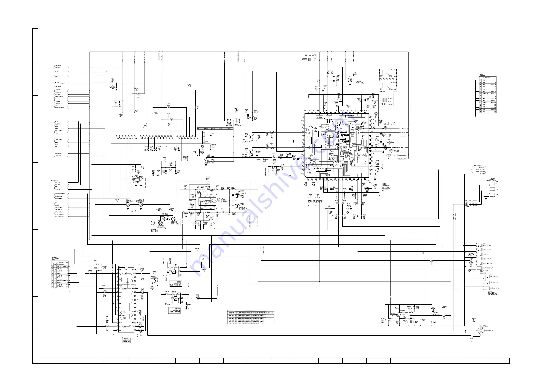
Page 65: ...1 2 3 4 5 6 7 8 9 10 11 12 13 14 15 16 17 18 19 20 A B C D E F G H I J DV NC70 W DV NC70X RU DV NC70 W DV NC70X RU 74 75 12 8 VCR MAIN 3 CIRCUIT SCHEMATIC DIAGRAM ...
Page 66: ...1 2 3 4 5 6 7 8 9 10 11 12 13 14 15 16 17 18 19 20 A B C D E F G H I J DV NC70 W DV NC70X RU DV NC70 W DV NC70X RU 76 77 12 9 MPX SKEW CIRCUIT SCHEMATIC DIAGRAM ...
Page 67: ...1 9 F B3 5 2 0 F B3 5 2 3 F B3 5 2 4 F B3 5 2 5 F B3 5 2 6 F B3 5 2 1 F B3 5 2 2 R3 6 3 7 R3 6 3 5 R3 6 3 3 R3 6 3 1 T P3 5 3 0 T P3 5 3 1 T P3 5 3 2 T P3 5 3 3 T P3 5 3 4 T P3 5 3 5 T P3 5 3 6 T P3 5 3 7 T P3 5 3 8 T P3 5 3 9 T P3 5 4 0 T P3 5 4 1 T P3 5 4 2 T P3 5 4 3 T P3 5 4 7 T P3 5 5 4 T P3 5 5 5 T P3 5 5 6 T P3 5 5 7 T P3 5 5 0 T P3 5 4 9 F B3 5 1 7 T P3 5 4 8 T P3 5 5 1 R3 6 3 6 CN3 5 0 1 ...
Page 68: ... 0 3 T P3 7 3 2 C3 7 5 2 R3 7 3 3 R3 7 3 1 R3 7 2 4 R3 7 2 3 C3 7 4 3 C3 7 4 2 R3 7 2 0 C3 7 4 0 F B3 7 0 1 T P3 7 2 0 R3 7 3 5 R3 7 3 4 C3 7 5 1 C3 7 3 9 R3 7 3 8 R3 7 3 7 R3 7 3 6 R3 7 2 8 R3 7 2 6 C3 7 4 1 T P3 7 2 1 RJ 3 1 0 4 R3 7 2 9 C3 7 5 0 R3 7 2 1 R3 7 2 2 T P3 7 2 5 C3 7 5 4 C3 7 4 5 C3 7 4 4 R3 7 2 7 R3 7 2 5 C3 7 4 6 C3 7 4 7 Z 3 Z 2 Z 1 RJ 3 1 0 5 Z 4 R3 3 1 2 RJ 3 1 0 6 T P3 3 3 0 R...
Page 69: ...82 DV NC70 W DV NC70X 70RU A B C D E F G H I J 1 2 3 4 5 6 7 8 9 10 DVD OPERATION PWB SIDE A Symbol SIDE B ...
Page 70: ...83 DV NC70 W DV NC70X RU 10 11 12 13 14 15 16 17 18 19 A B C D E F G H I J 1 2 3 4 5 6 7 8 9 10 VCR OPERATION PWB SIDE A Symbol SIDE B ...
Page 71: ...1 2 3 4 5 6 7 8 9 10 11 12 13 14 15 16 17 18 19 20 A B C D E F G H I J DV NC70 W DV NC70X RU DV NC70 W DV NC70X RU 84 85 POWER PWB SIDE A Symbol ...
Page 72: ...1 2 3 4 5 6 7 8 9 10 11 12 13 14 15 16 17 18 19 20 A B C D E F G H I J DV NC70 W DV NC70X RU DV NC70 W DV NC70X RU 86 87 POWER PWB SIDE B ...
Page 73: ...1 2 3 4 5 6 7 8 9 10 11 12 13 14 15 16 17 18 19 20 A B C D E F G H I J DV NC70 W DV NC70X RU DV NC70 W DV NC70X RU 88 89 VCR MAIN PWB SIDE A Symbol ...
Page 74: ...1 2 3 4 5 6 7 8 9 10 11 12 13 14 15 16 17 18 19 20 A B C D E F G H I J DV NC70 W DV NC70X RU DV NC70 W DV NC70X RU 90 91 VCR MAIN PWB SIDE B ...
Page 75: ...92 DV NC70 W DV NC70X 70RU A B C D E F G H I J 1 2 3 4 5 6 7 8 9 10 MPX SKEW PWB SIDE A Symbol ...
Page 76: ...93 DV NC70 W DV NC70X RU 10 11 12 13 14 15 16 17 18 19 A B C D E F G H I J 1 2 3 4 5 6 7 8 9 10 MPX SKEW PWB SIDE B ...
Page 77: ...94 DV NC70 W DV NC70X 70RU A B C D E F G H I J 1 2 3 4 5 6 7 8 9 10 M E M O ...
Page 78: ...APF0JW226MY 22 6 3V Electrolytic AB C3331 VCKYCY1CB104KY 0 1 16V Ceramic AB C3333 VCKYCY1CB104KY 0 1 16V Ceramic AB C3336 VCCCCY1HH101JY 100p 50V Ceramic AA C3341 VCEAPF0JW226MY 22 6 3V Electrolytic AB C3342 VCKYCY1CB104KY 0 1 16V Ceramic AB C3343 VCKYCY1HB103KY 0 01 50V Ceramic AA C3344 VCEAPF0JW226MY 22 6 3V Electrolytic AB C3345 VCKYCY1HB103KY 0 01 50V Ceramic AA C3346 VCEAPF0JW476MY 47 6 3V El...
Page 79: ...5 1 16W Metal Oxide AA R3205 VRS CY1JF330JY 33 1 16W Metal Oxide AA R3206 VRS CY1JF102JY 1k 1 16W Metal Oxide AA R3207 VRS CY1JF330JY 33 1 16W Metal Oxide AA R3208 VRS CY1JF680FY 68 1 16W Metal Oxide AA C3361 VCKYCY1CB104KY 0 1 16V Ceramic AB C3501 VCKYCY1CB104KY 0 1 16V Ceramic AB C3502 VCKYCY1CB104KY 0 1 16V Ceramic AB C3503 VCKYCY1CB104KY 0 1 16V Ceramic AB C3504 VCCCCY1HH101JY 100p 50V Ceramic...
Page 80: ...CY1JF273JY 27k 1 16W Metal Oxide AA R3731 VRS CY1JF472JY 4 7k 1 16W Metal Oxide AA R3733 VRS CY1JF472JY 4 7k 1 16W Metal Oxide AA R3734 VRS CY1JF183JY 18k 1 16W Metal Oxide AA R3736 VRS CY1JF101JY 100 1 16W Metal Oxide AA R3209 VRS CY1JF102JY 1k 1 16W Metal Oxide AA R3210 VRS CY1JF330JY 33 1 16W Metal Oxide AA R3211 VRS CY1JF750FY 75 1 16W Metal Oxide AA R3212 VRS CY1JF102JY 1k 1 16W Metal Oxide A...
Page 81: ... R3741 VRS CY1JF102JY 1k 1 16W Metal Oxide AA R3742 VRS CY1JF102JY 1k 1 16W Metal Oxide AA R3743 VRS CY1JF101JY 100 1 16W Metal Oxide AA R3744 VRS CY1JF102JY 1k 1 16W Metal Oxide AA R3750 VRS CY1JF153JY 15k 1 16W Metal Oxide AA R3751 VRS CY1JF823JY 82k 1 16W Metal Oxide AA R3752 VRS CY1JF823JY 82k 1 16W Metal Oxide AA R3753 VRS CY1JF153JY 15k 1 16W Metal Oxide AA R3756 VRS CY1JF273JY 27k 1 16W Met...
Page 82: ...443TV1E 2SB1443TV AE DVD_3 3V SW Q938 VSKRC102S 1Y KRC102S AA Q939 VS2SA1271 Y 1 2SA1271 Y AC DVD D_5V SW Q940 VSKRC103S 1Y KRC103S AA Q941 VS2SA1271 Y 1 2SA1271 Y AC DVD PC_5V SW Q942 VSKRC103S 1Y KRC103S AA DIODES AND LED S å D901 VHDRL1N4005 1Y RL1N4005 AC å D902 VHDRL1N4005 1Y RL1N4005 AC å D903 VHDRL1N4005 1Y RL1N4005 AC å D904 VHDRL1N4005 1Y RL1N4005 AC å D905 RH EX0617GEZZY Zener 6 2A AA D9...
Page 83: ...ectrolytic AB C948 VCEA9M0JW227M 220 6 3V Electrolytic AB C949 VCEA9M1HW105M 1 50V Electrolytic AB C950 VCEA9M0JW476M 47 6 3V Electrolytic AB C952 VCEA9M1CW226M 22 16V Electrolytic AB RESISTORS å R901 VRD RA2EE474JY 470k 1 4W Carbon AA å R902 RR HZ0014GEZZY 12M 1 2W Alumina Ceramic AE å R903 VRS CY1JF564JY 560k 1 16W Metal Oxide AA å R905 VRD RM2HD222JY 2 2k 1 2W Carbon AA å R907 VRD RA2HD184JY 18...
Page 84: ...6V Ceramic AA C508 VCEA9M1HW475M 4 7 50V Electrolytic AB C509 VCKYCY1HF103ZS 0 01 50V Ceramic AA C510 VCCCCY1HH270JS 27p 50V Ceramic AA C512 VCKYCY1HF103ZS 0 01 50V Ceramic AA C513 VCKYCY1HF103ZS 0 01 50V Ceramic AA C514 VCKYCY1HF103ZS 0 01 50V Ceramic AA C515 VCKYCY1HB331KS 330p 50V Ceramic AA C516 VCEA9M1HW105M 1 50V Electrolytic AB C517 VCEA9M1HW335M 3 3 50V Electrolytic AB C518 VCKYCY1CB333KS ...
Page 85: ...100 6 3V Electrolytic AB C2023 VCEA9M1CW226M 22 16V Electrolytic AB C2024 VCEA9M1CW226M 22 16V Electrolytic AB C2025 VCEA9M1CW226M 22 16V Electrolytic AB C2026 VCKYCY1CF104ZS 0 1 16V Ceramic AA C6028 VCEA9M0JW227M 220 6 3V Electrolytic AB C603 VCEA9M1CW106M 10 16V Electrolytic AB C604 VCKYCY1HB821KS 820p 50V Ceramic AA C605 VCEA9M1CW106M 10 16V Electrolytic AB C606 VCEA9M1HW475M 4 7 50V Electrolyt...
Page 86: ...tal Oxide AA R609 VRS CY1JF473JS 47k 1 16W Metal Oxide AA R610 VRS CY1JF183JS 18k 1 16W Metal Oxide AA R611 VRS CY1JF101JS 100 1 16W Metal Oxide AA R615 VRS CY1JF153JS 15k 1 16W Metal Oxide AA R616 VRS CY1JF183JS 18k 1 16W Metal Oxide AA R619 VRS CY1JF470JS 47 1 16W Metal Oxide AA R620 VRS CY1JF153JS 15k 1 16W Metal Oxide AA R621 VRD RA2EE4R7JY 4 7 1 4W Carbon AA R623 VRD RA2BE223JY 22k 1 8W Carbo...
Page 87: ...inued R1910 VRD RA2BE103JY 10k 1 8W Carbon AA R1912 VRD RA2BE471JY 470 1 8W Carbon AA R1913 VRD RA2BE471JY 470 1 8W Carbon AA R1915 VRD RA2BE222JY 2 2k 1 8W Carbon AA R1916 VRD RA2BE222JY 2 2k 1 8W Carbon AA R1917 VRD RM2HD102JY 1k 1 2W Carbon AA R1918 VRS CY1JF224JS 220k 1 16W Metal Oxide AA R1919 VRD RA2BE103JY 10k 1 8W Carbon AA R1920 VRD RA2BE103JY 10k 1 8W Carbon AA R1921 VRS CY1JF103JS 10k 1...
Page 88: ...lytic AB C1709 VCEA9M1AW226M 22 10V Electrolytic AB C1710 VCCCCY1HH5R0CY 5p 50V Ceramic AA C1711 VCCCCY1HH6R0DY 6p 50V Ceramic AA C1712 VCKYCY1HF103ZY 0 01 50V Ceramic AA C1713 VCKYCY1HF103ZY 0 01 50V Ceramic AA C1714 VCEA9M1HW105M 1 50V Electrolytic AB C1715 VCKYCY1HF103ZY 0 01 50V Ceramic AA C1718 VCEA9M0JW226M 22 6 3V Electrolytic AB C1720 VCCCCY1HH470JY 47p 50V Ceramic AA C1723 VCEA9M1CW106M 1...
Page 89: ...LDW1033CE00 Nylon Band Holder AA 423 RMOTM1097AJZZ Loading Motor AM 424 NPLYM0001AJZZ Loading Motor Pulley AB 425 QSW B0011AJZZ Loading Motor Switch AE 426 NBLTK0068AJZZ Loading Belt AD 427 NGERH1332AJZZ Pulley Gear AC 428 NGERP1016AJZZ Tray Pinion AC 429 LCHSMA001WJZZ Base Chassis AL 431 LCRA 0012GEZZ Disc Clamper AF 432 LX WZ0102GEFD York Washer AB 433 PMAGS1001GEZZ Clamper Magnet AF 434 GCOVA21...
Page 90: ...Z Clutch Lever AC 524 MLEVP0348AJZZ Supply Main Brake Ass y AB 525 MLEVP0349AJZZ Take up Main Brake Ass y AC 527 MSLiP0016AJZZ Sifter AD 528 MSPRDA006WJFJ Reverse Guide Spring2 AB 529 MSPRD0213AJFJ Tu Loading Double Action AB Spring 530 MSPRD0214AJFJ Sup Loading Double Action AB Spring 531 MSPRT0439AJFJ Pinch Double Action Spring AB 532 MSPRT0438AJFJ Main Brake Spring AB 533 MSPRT0416AJFJ Tension ...
Page 91: ...3 QCNW A693WJZZ Connecting Cord AE NC70X RU 44 QCNW A358WJZZ Connecting Cord AD 45 QCNW A765WJZZ Connecting Cord AE 46 QCNW A360WJZZ Connecting Cord AC 47 QCNW A361WJZZ Connecting Cord AG 48 QCNW A401WJZZ Connecting Cord AG PWR VCR 58 QCNW A362WJZZ Pickup Relay FFC AD 59 PSPAZA074WJZZ Spacer 60 PSPAZA031WJZZ Spacer AD 61 PSPAZA134WJZZ Spacer 62 PSPAZA036WJZZ Spacer a LX HZ3087GEFN Screw for Mecha ...
Page 92: ... 433 429 401 4 424 401 3 401 2 409 423 422 421 420 426 427 428 431 425 419 410 409 410 409 401 6 401 401 5 409 413 435 401 7 401 11 401 10 401 1 401 9 401 8 418 401 13 401 12 Dry Coating Dry Coating Dry Coating Dry Coating Grease Grease Grease Grease Grease When touching the pickup wear an earth band to prevent breakage by static electricity å Caution 401 14 ...
Page 93: ... A 566 566 553 222 221 555 517 559 556 570 202 566 565 562 566 563 501 533 509 502 558 524 532 507 551 549 573 201 203 549 551 516 571 508 215 506 512 536 531 518 513 224 545 567 541 519 528 204 538 537 561 208 529 510 534 511 530 523 548 546 219 527 535 209 210 211 212 213 214 535 543 505 543 504 521 552 525 572 544 560 564 520 205 216 205 574 Grease ...
Page 94: ...70X RU Ref No Part No Description Code Ref No Part No Description Code CASSETTE HOUSING CONTROL EXPLODED VIEW A B C D E F G H 1 2 3 4 5 6 A A 300 302 306 304 301 314 314 305 309 315 303 312 313 317 308 307 310 311 Grease ...
Page 95: ...scription Code A B C D E F G H 1 2 3 4 5 6 Q P O H G I J A G R F N M J S E F I H R D E B A M N O Q P K K S B D T T i 2 c c c c c h 32 h e a d 31 c 26 33 21 c 35 c 58 43 42 27 b 47 40 c 29 38 24 45 44 46 25 30 28 g 48 d f j 34 41 C C i i C C 23 59 60 61 62 CABINET EXPLODED VIEW ...
Page 96: ...NC70X RU Ref No Part No Description Code Ref No Part No Description Code A B C D E F G H 1 2 3 4 5 6 FRONT PANEL EXPLODED VIEW 600 13 600 6 600 14 600 11 600 9 600 8 600 10 600 7 600 12 600 5 600 600 1 600 2 600 4 600 3 ...
Page 97: ... NC70RU Operation Manual RRMCGA107WJSA NC70W RRMCGA114WJSA NC70 X RU Remote Control unit QCNW 8547AJZZ RF Cable SPAKP0209AJZZ Wrapping Paper TLABV0182AJZZ NC70RU TLABZA194WJZZ NC70W TLABZA121WJZZ NC70 TLABZA122WJZZ NC70X No Label Not Replacement Items SPAKCA310WJZZ NC70 W X SPAKCA315WJZZ NC70RU Packing Case SPAKXA023WJZZ Packing Add QCNW 8388AJZZ AV Cable SSAKA0001AJZZ Operation Manual Polyethylen...
Page 98: ...115 DV NC70 W DV NC70X RU Ref No Part No Description Code Ref No Part No Description Code ...
Page 99: ...ita Tochigi 329 2193 Japan COPYRIGHT 2002 BY SHARP CORPORATION ALL RIGHTS RESERVED No part of this publication may be reproduced stored in a retrieval system or transmitted in any form or by any means electronic mechanical photocopying recording or otherwise without prior written permission of the publisher D SEM P SMM TQ1393 S Nov 2002 Printed in JAPAN SA DS NR ...