background image

XL-30H/30W

– 18 –

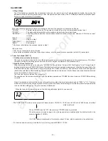
7. Key input diagnosis Test Mode (TEST 6)

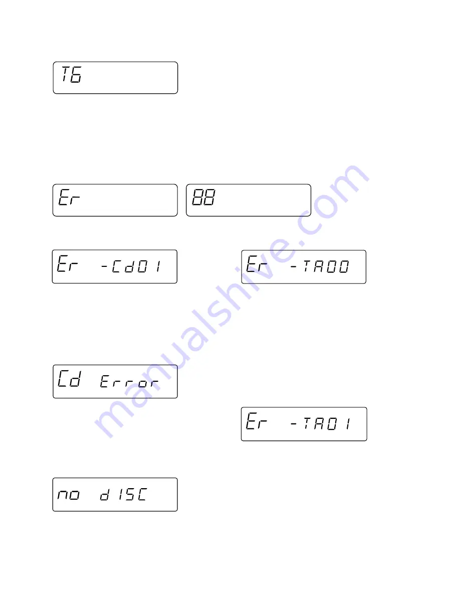
When the test mode is set, the following indication appears.

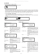
ERROR LIST

PU-IN SW detection error

CD read error

Error content ........... Disc data cannot be read properly or

even if it can be read, the disc is not a
playable one.

Probable  cause ....... The disc is loaded upside down, not CD-

DA, scratches, stains, etc.

Action ...................... Open the CD lid, then reload the disc

correctly. Remove the scratches or stains
on the disc.

NO DISC

Tape mechanism error 1

Tape mechanism error 2

Error content ............ The detection SW cannot detect ON

after a fixed period of time even if the
microcomputer controls the CD pickup
to return to the innermost position.

Probable cause ........ Defective or poorly connected PU-IN

SW or slide motor.

Action ....................... Solve the problem and turn on the power

again.

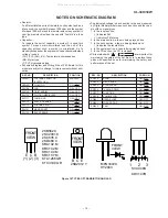
Error content ........... Focusing is impossible.
Probable  cause ....... The disc is loaded upside down, not CD-

DA, scratches, stains, etc.

Action ...................... Open the CD lid, then reload the disc

correctly. Remove the scratches or stains
on the disc.

Error content ........... The detection SW "CAM-SW" cannot

detect ON (mechanism in operation) even
if the motor and solenoid are controlled
to play back, fast forward, rewind, or
record the tape.

Probable cause ....... Mechanism is in operation when this

message appears: Defective or poorly
connected CAM-SW. Mechanism stops:
Defective or poorly connected motor or
solenoid.

Action ...................... Solve the problem and turn on the power

again.

Error content ........... Initialization cannot be completed when

the microcomputer controls the motor
and solenoid to initialize the tape
mechanism (to set the mechanism to the
stop mode). The detection SW "CAM-
SW" cannot detect OFF While the
mechanism is in operation.

Probable cause ....... Mechanism is in operation when this

message appears: Defective or poorly
connected CAM-SW. Mechanism stops:
Defective or poorly connected motor or
solenoid.

Action ...................... Solve the problem and turn on the power

again.

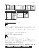
This test mode is intended to check whether all the main unit buttons can be detected. Accordingly, in this test mode checking
as to whether the "POWER" button was pressed after all the buttons shown below were pressed is performed. If the result is
OK, OK is indicated. Even any one of keys was not pressed, an error is indicated. In case of OK termination or error termination
exit from this mode occurs when the "POWER" button is pressed next time, and the standby mode is set.

1. In case of "FF/FWD" + "REC PAUSE"

Since SURROUND and RDS are not provided, the following 11 buttons are detected as all buttons.
PLAY, JOG MODE, BAND, BASS/TREBLE, FUNCTION, MEMORY/SET, REC PAUSE, REW, FF, STOP, CLOCK/TIMER/
SLEEP.

The OK/NG indication of test result is as follows.

All manuals and user guides at all-guides.com

Summary of Contents for CP-XL40H

Page 1: ... safety the set should be restored to its original condition and only parts identical to those specified should be used This document has been published to be used for after sales service only The contents are subject to change without notice XL 30H Micro Component System consisting of XL 30H main unit and CP XL40H speaker system Illustration XL 30H XL 30W Micro Component System consisting of XL 3...

Page 2: ...NSTRUMENT ADVERSEL USYNLIG LASERSTRALING VED ABNING SE IKKE IND I STRALEN HELLER IKKE MED OPTISKE INSTRUMENTER VARO AVATTAESSA OLET ALTTIINA NAKYMATON LASERSATEILYLLE ALA TUIJOTA SATEESEEN ALAKA KATSO SITA OPTISEN LAITTEEN LAPI VARNING OSYNLIG LASERSTRALNING NAR DENNA DEL AR OPPNAD STIRRA EJIN I STRALEN OCH BETRAKTA EJ STRALEN GENOM OPTISKT INSTRUMENT ADVERSEL USYNLIG LASERSTRALING NAR DEKSEL APNE...

Page 3: ...A Unit Judgment OK The GOOD lamp lights NG The NG lamp lights and the buzzer sounds VOLTAGE SELECTION FOR XL 30W The voltage selector is located on the rear panel of the unit If adjustment is necessary use a screwdriver in order to turn the selector in either direction until the correct voltage figure is displayed in the window QACCE0001SJ00 QACCA0001SJ00 QACCB0001SJ00 QPLGA0253AFZZ PROBE AC OUT U...

Page 4: ... 1 2 Depth 249 mm 9 13 16 Weight 2 7 kg 6 0 lbs Amplifier section Output power XL 30H for Europe PMPO 28 W total MPO 14 W 7 W 7 W DIN 45 324 RMS 10 W 5 W 5 W DIN 45 324 Output terminals Speakers 4 ohms Headphones 16 50 ohms recommended 32 ohms Tuner section Frequency range For XL 30H FM 87 5 108 MHz AM 522 1 620 kHz Compact disc player section Type Compact disc player Signal readout Non contact 3 ...

Page 5: ... Button 15 Memory Set Button 16 Clock Timer Sleep Button 17 Band Selector Button 18 CD Review Button TAPE Rewind Button TUNER Tuning Down Button 19 Function Selector Button 20 Headphone Socket 21 CD Eject Button 22 Remote Control Sensor 23 Volume Select Button 24 CD Play Pause Button TAPE Play Button 25 Jog Dial 26 CD Cue Button TAPE Fast Forward Button TUNER Tuning Up Button 27 Volume Jog Dial Se...

Page 6: ...with a soft cloth Exposing the sensor on the main unit to strong light may interfere with operation Change the lighting or the direction of the unit Keep the remote control away from moisture excessive heat shock and vibrations 0 2m 6m 8 20 Remote control CP XL40H 1 2 3 3 4 5 10 11 2 6 7 8 9 12 13 14 20 22 15 16 17 18 19 21 1 OPERATION MANUAL XL 30H 30W RESETTING THE MICROCOMPUTER 1 3 3 2 3 AC INP...

Page 7: ...TING THE MICROCOMPUTER 2 Perform steps 1 8 above PREPARATION FOR USE FOR XL 30W Only AM FM interval span The International Telecommunication Union ITU has established that member countries should maintain either a 10 kHz or a 9 kHz interval be tween broadcasting frequencies of any AM station The illustration shows the 9 kHz interval zones re gions 1 and 3 and the 10 kHz interval zone re gion 2 Thi...

Page 8: ...FM aerial 1 For XL30W Remote control 1 AC power lead 1 AM loop aerial 1 For XL30H 4 Connections 1 Connect the AM and FM aerials 2 Connect the speaker system 3 Connect the AC power lead 2 1 3 1 2 FM aerial AM loop aerial White line Right speaker Left speaker 1 2 RATED LINE VOLTAGE 220V ı 240V AC 230 V 50 Hz XL 30H for Europe AC 110V 127V or 220V 240V 50 60 Hz ANTENNA LOOP FM 75 OHMS 1 2 3 AM loop a...

Page 9: ...ng the corner marked PUSH CLOSE 6 Press the CD button 7 Adjust the VOLUME control 5 Listening to a CD Listening to the radio 7 1 Press the ON STAND BY button to turn the power on 2 Press the FUNCTION button until TP appears 3 Open the cassette door by pushing the area marked PUSH EJECT 4 Load a cassette 5 Press the button 6 Adjust the VOLUME control 8 Recording from a CD 1 Press the ON STAND BY bu...

Page 10: ...the power supply plug from the wall outlet before starting to disassemble the unit 3 Take off nylon bands or wire holders where they need to be removed when disassembling the unit After servicing the unit be sure to rearrange the leads where they were before disassembling 4 Take sufficient care on static electricity of integrated circuits and other circuits when servicing Figure 10 4 Figure 10 5 C...

Page 11: ...an it How to remove the motor See Figs 11 5 1 Remove the main belt 2 Remove the screws D1 x 2 pcs to remove the motor bracket 3 Remove the screws D2 x 3 pcs to remove the motor Note Whenmountingthemotor payattentiontothemotormounting angle Figure 11 2 Figure 11 3 Figure 11 4 Figure 11 5 A Pinch Roller B1 x1 Pinch Roller Pawl REMOVING AND REINSTALLING THE MAIN PARTS Main Belt C1 x1 FF REW Belt C2 x...

Page 12: ...rom the motor pulley 3 Remove the screws G2 x 2 pcs to remove the jog motor Note When putting on the belt ascertain that the belt is not twisted and clean it Figure 12 2 Figure 12 3 G2 x2 ø2x5mm Worm Gear Jog Belt G1 x1 Jog Motor Holder Jog Motor Display PWB Figure 12 1 How to remove the flywheel See Fig 12 1 1 Remove the belt 2 Remove the stop washer E1 x 1 pc with a small precision screwdriver t...

Page 13: ...age Frequency Frequency Display Setting Adjusting Parts Instrument Connection Adjusting Parts Instrument Connection Display Frequency 98 00 MHz 98 00 MHz VR351 1 Input CNP301 30 dBµV Output Speaker Terminal FM RF XL 30H W Signal generator 1 kHz 75 kHz dev FM modulated FM Band 87 50 MHz fL L303 1 Coverage 3 4 0 1 V FM RF 98 00 MHz 98 00 MHz L302 2 10 30 dB Test Stage Frequency Frequency Display Set...

Page 14: ...ode To turn on the specific test mode press the POWER button holding down the following two buttons in the ordinary stand by mode power off state In this case only the main unit button is valid Even when the POWER of remote control button is set to on the test mode is not turned on Ordinary test mode 1 CD Test Mode TEST 1 Volume JOG Dial Selector FF FWD 2 Tuner Test Mode TEST 2 Volume JOG Dial Sel...

Page 15: ...ep 5 If the focus is disturbed after it has been set the process returns to step 1 3 Step 3 Mode The laser is kept lighting The processing until turning on of CLV servo of CD initialization operation flow is executed and the next button input is waited The focus servo is turned on and focus search is performed The focus search is repeated until the focus is set If the following buttons are pressed...

Page 16: ...ights for one second The TUNER TEST2 mode is set as a result of Volume Select POWER IF AC is set to OFF in the TEST2 mode the initial state is restored When POWER is set to OFF the memory of TEST2 mode is protected When the power is turned on again the ordinary operation is enabled while the data is stored in the memory besides TUNER If AC OFF state is maintained in this state for about 1 2 day st...

Page 17: ...me as that of ordinary operation excepting test mode setting 2 The sound volume control with the sound volume UP DOWN button is only the following 3 steps unlike the ordinary state Volume STEP 0 Volume 14 dB STEP 23 Volume 0 STEP 30 3 BASS TREBLE and SURROUND are switched when button operation is performed The current time and timer time are set in the following procedure to perform the timer play...

Page 18: ... appears Defective or poorly connected CAM SW Mechanism stops Defective or poorly connected motor or solenoid Action Solve the problem and turn on the power again Error content Initialization cannot be completed when the microcomputer controls the motor and solenoid to initialize the tape mechanism to set the mechanism to the stop mode The detection SW CAM SW cannot detect OFF While the mechanism ...

Page 19: ... as K and M are used the symbol K means 1000 ohm and the symbol M means 1000 kohm and the resistor without any symbol is ohm type resistor Besides the one with Fusible is a fuse type Capacitor To indicate the unit of capacitor a symbol P is used this symbol P means micro micro farad and the unit of the capacitor without such a symbol is microfarad As to electrolyticcapacitor theexpression capacita...

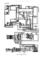
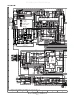
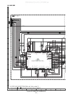
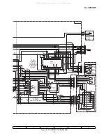
Page 20: ...D AM IN NC IF IN IF REQ SW VCC AM ANT AM OSC VD301 1 SVC348S VD301 2 SVC348S VR351 10K B FM MUTE LEVEL 23 T351 5V AM IF MUTE R MUTE MO ST L CH OUT R CH OUT MPX VCO AM LOW CUT FM AM OUT MPX IN AM OSC OUT FM AFC AM RF IN VSM AM OSC IN AM MIX OUT AM IF IN GND REG FM IF IN SD STEREO FM DET PHASE AM FM IF OUT PHASE FM IF DET FM MPX AM IF 4 5MHz Q351 SWITCHING R_MUTE PLL CONTROLLER ZD351 MTZJ5 1B Q360 F...

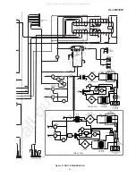
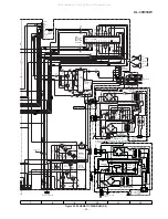
Page 21: ...UT A_12V USWD_5R6V P_CONT D_GND A GND CD R M GND M_12V D_GND CD_6R2V 11 L CH L CH 1 2 3 2 1 GND CNS652 Q682 Q681 Q683 T F D651 D654 VOLTAGE REGULATOR RLY681 LF651 LINE FILTER SO651 AC POWER INPUT SOCKET AC230V 50Hz T681 SUB POWER TRANSFORMER D681 D684 CNP681 T651 MAIN POWER TRANSFORMER F651 T2 5A L 250V F653 T1A L 250V 8 1 3 9 6 5 1 2 REC R CH REC L CH NC FUNCTION VOLUME EQUALIZER 2 2 1 1 3 1 3 2 ...

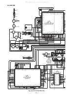
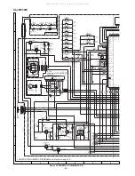
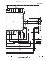
Page 22: ... 76 77 78 79 80 81 82 83 84 85 86 87 88 89 90 91 92 93 94 95 96 97 98 99 100 X801 16 93MHz A_GND 5V 1 24 2 3 4 5 6 7 8 23 22 21 20 19 18 17 9 16 10 15 11 14 12 13 IC801 TA2109F SERVO PRE AMP E F B A SW CD 5V SW801 OPEN CLOSE CFW807 1 2 CFW701 1 2 SW700 JOG A B C 1 2 3 CNP706 CNS706 UP DOWN 5V Q706 Q707 SWITCHING LED B A_12V 1 2 3 CNS707 SYS STOP REMOCON RESET U COM VDD U CON 5V P CONT IC804 LA6541...

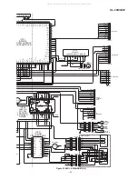
Page 23: ...S802 1 2V 5V E A B F C VREF 5V 1 2V 5V E A B F C TR TR FO FO LD V PD GND CD 5V M_GND CNS605 1 2 3 4 5 6 7 IC702 TA7291S 8 9 MVOL_DW MVOL_UP CNP705 1 2 CNS705 M M701 JOG MOTOR LOADING MOTOR DRIVER IC804 LA6541D VCC MUTE VCC REG RESET RES CD REG REG IN OUT SP SP SL SL FO FO TR TR CD STB 2 3 4 5 6 7 8 9 10 11 12 13 14 15 16 17 18 19 20 21 22 23 24 25 26 27 28 29 30 CD_6R2V CD_6R2V 10 1 2 3 4 5 6 7 8 ...

Page 24: ... 10K D GND U_CON5V SOL MOT REC RUN_PLS BIAS B_CAN TAPE_SW 0V 0V 1 5V 1 5V 0 3V 0 3V 0 8V 0 8V 0 8V 0 8V 0 3V 0 3V 8V 10V 0 3V 8 3V 0V 0V 0V 0V 0V 0V 11 7V 11 7V 0V 0V 0V 2 6V 0V 7 8V 8 3V 0V 4 7V 3 2V 0 7V 0V 11 9V 11 8V 11 8V 11 7V 11 7V 11 7V 0V 4 4V 0 6V 4 9V 4 9V 10 1V 10 2V 4 6V 4 6V 0V 0V 0V 0V 0V 0 6V 0 7V 0 7V 0 9V 0 9V 5 2V 0V 2 6V 2 6V 3 9V 0V 0V 3 5V 3 7V 11 4V 1 7V 5 1V 4 8V 0 1V 0 1V ...

Page 25: ...FM ST SD DI CE DO CL R CH L CH F653 T1A L 250V 5V 4 8V 4 8V R418 1K R420 1K R417 1K R419 1K C415 10 16 SPEAKERS 5 R627 10K 1 2 3 1 2 3 GND1 20V Q604 2SD2012 Y D603 1N4148 CNP653 2 1 D684 D681 D683 RLY681 D685 1N4004 CNP681 3 2 1 226 TO TAPE MECHANISM CHASSIS 2 1 C684 0 047 C688 0 022 R682 1 2K C685 47 16 R681 47 ZD681 MTZJ6 8A Q681 2SD468C C686 0 022 Q682 2SD468 C R684 1 2K C689 47 16 R683 47 ZD68...

Page 26: ...P CLEAR R708 2 2K SW724 REC PAUSE R709 1 5K SW723 BAND R710 1 2K SW722 BASS TREBLE R711 1 2K R725 10K R724 C703 0 022 L701 100µH R701 10K R702 10K SW709 ON STAND BY SW710 CLOCK TIMER SLEEP R721 10K R722 10K SW721 MEMORY SET SW711 TUNING UP R738 1K R737 1K R739 1K R740 1K R741 1K R734 1K R733 1K R732 1K R731 1K R743 1K X701 8 MHz C702 22P CH C701 22P CH R728 1K R729 47K R727 47K X702 32 768kHz BI70...

Page 27: ...TE 2 5V 2 5V 2 5V 2 5V 2 5V 2 5V 2 5V 2 5V 2 5V 2 5V 2 5V 2 5V 2 5V 2 5V 2 5V 2 5V 2 5V 2 5V 2 5V 2 5V 2 5V 2 5V 2 5V 2 5V 2 5V 2 5V 2 5V 2 5V 2 5V 2 5V 2 5V 2 5V 2 5V 5V 5V 5V 5V 1 7V 3 3V 2 6V 2 6V 2 4V 1 9V 6V 4 6V 4 3V 4 3V 4 3V 4 3V 4V 5V 5V 5V 5V 5V 5V 5V 5V 5V 5V 5V 5V 5V 5V 5V 5V 5V 5V 5V 5V V V 5V 5V 5V 5V 0V 0V 0V 0V 0V 0V 0V 0V 0V 0V 0V 0V 0V 0V BACK_LIGHT P_MUTE LID_PRO CCE CLID_DW CLI...

Page 28: ... 2 1 NC NC NC BUS3 BUS2 BUS3 CCE BUCK BUS1 BUS2 BUS0 CLID_SW BUS0 CCE BUS1 CD_RES CD_RES BUCK PU_IN CD_STB 4 9V 3 3V 4V 4 3V 4 3V 4 3V 4 3V 2 4V 2 3V 2 4V 2 6V 4 3V 1 8V 2 2V 2 2V 2 2V 2 2V 2 2V 2 2V 1 4V 2 1V 2 1V 2 1V 2 1V 2 1V 2 1V 2 1V 2 1V 2 1V 2 1V 2 1V 2 1V 2 1V 2 1V 2 1V 2 1V 2 1V 2 1V 2 1V 4 3V 0 6V 2 4V 1 2V 2 5V 2 5V 2 5V 1 7V 1 4V 5V 5V 5V 5V 5V 5V 5V 5V 5V 5V 5V 5V 5V 5V 5V 5V 5V 0V 0...

Page 29: ...V 3 1V 0V 0V 0V 0V 0V 0V 2 8V 2 8V 2 5V 2 2V 2 5V 2 8V 2 8V 2 2V 2 2V 2 2V 2 1V 2 1V 2 1V 2 1V 6 3V 2 2V 5 1V 5 6V 5V 5V 5V 2V 4 1V 3 4V 3 4V 4 3V 2 5V 5V 0V 0V 1 7V 2 2V 2 2V 2 1V 2 1V 2 1V 2 1V 2 1V 2 1V 2 1V 2 1V 2 1V 2 1V 2 1V 2 1V 2 1V 2 1V 2 1V TO MAIN PWB TR FO FO LD VR PD GND TR C F B A E VREF 5V SP SP SL SL PU IN GND TR 5V 1 2V E A B F C GND PU IN SL SL SP SP PICKUP UNIT GND PD VR LD FO F...

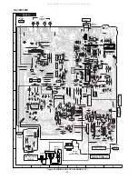
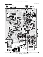
Page 30: ... 8 7 6 5 4 3 2 1 12 10 2 4 6 8 9 3 7 1 CNS605 FROM CD PWB CNS652 1 2 C697 FROM POWER PWB ANTENNA TERMINAL CNS703 TO DISPLAY PWB 5 BK GY GY GY GY GY GY GY GY GY GY GY GY BK 7 6 5 4 3 2 1 CNS901 P36 6 D TO TAPE MECHANISM PWB CNP901 CNS101 PK WH RD WH RD WH WH BK BK YL BL BK WH BK ERASE HEAD RECOED PLAYBACK HEAD 1 2 3 1 2 3 1 7 B C E E C B B C E E C B B C E B C E 11 10 9 8 7 6 5 4 3 2 1 J601 HEADPHON...

Page 31: ...2 2 3 1 C697 FROM POWER PWB SO301 FM 75 OHMS ANTENNA ANTENNA TERMINALS CNS703 TO DISPLAY PWB 5 BK GY GY GY GY GY GY GY GY GY GY GY GY BK 7 6 5 4 3 2 1 CNS901 P36 6 D TO TAPE MECHANISM PWB CNP901 CNS101 PK WH RD WH RD WH WH BK BK YL BL BK WH BK ERASE HEAD RECOED PLAYBACK HEAD 1 2 3 1 2 3 1 7 B C E E C B B C E E C B B C E B C E 11 10 9 8 7 6 5 4 3 2 1 J601 HEADPHONES 8 7 6 5 4 3 2 1 P36 2 E P35 9 C ...

Page 32: ... 19 10 16 20 22 23 24 21 STOP CLEAR SW728 VOLUME JOG VOLUME SELECT 3 2 1 B C E B C E E C B 3 2 1 GY GY BK CFW701 TO MAIN PWB P30 6 H CNP703 1 2 3 4 5 6 7 8 9 10 11 3 SW721 BAND CLOCK TIMER SLEEP BASS TREBLE CNS702 P34 1 E P30 6 F 1 2 3 4 5 6 7 8 9 R7D8 R7D3 R7D5 R7D9 R7D1 R7D6 R710 C772 R7B3 R7B2 R708 R729 R783 R727 R721 R723 C702 R731 C701 R732 R711 R728 R733 R782 R725 R734 R724 R746 R743 R775 R7...

Page 33: ...OG VOLUME SELECT 3 2 1 B C E B C E E C B 3 2 1 GY GY BK CFW701 TO MAIN PWB P31 12 H CNP703 1 2 3 4 5 6 7 8 9 10 11 3 SW721 BAND CLOCK TIMER SLEEP BASS TREBLE CNS702 P35 7 E P31 12 E 1 2 3 4 5 6 7 8 9 D709 D708 D706 D707 D705 D704 R7D8 R7D3 R7D5 R7D9 R7D1 R7D6 R710 C772 R7B3 R7B2 R708 R729 R783 R727 R721 R723 C702 R731 C701 R732 R711 R728 R733 R782 R725 R734 R724 R746 R743 R775 R778 R741 R779 R740 ...

Page 34: ... WH RD WH GY WH GY WH GY TO MAIN PWB P30 1 G 1 2 CFW807 7 1 8 1 PICKUP UNIT CNP803 1 6 5 4 3 2 CD MOTOR PWB C CD PWB A3 PICK UP IN NSW801 NM801 SLED MOTOR NM802 SPINDLE MOTOR CNS802 CNS801 E C B SW801 OPEN CLOSE SWITCH PWB A6 L804 R843 R861 R862 R863 C860 R824 R80A IC801 R80B R80F R80C C849 C843 R827 C839 C847 C806 C846 C863 C805 C848 R806 C804 C802 R825 R804 C812 C807 C844 C820 C809 C810 C817 C83...

Page 35: ... WH GY WH GY WH GY TO MAIN PWB P31 7 G 1 2 CFW807 7 1 8 1 PICKUP UNIT CNP803 1 6 5 4 3 2 CD MOTOR PWB C CD PWB A3 PICK UP IN NSW801 NM801 SLED MOTOR NM802 SPINDLE MOTOR CNS802 CNS801 E C B SW801 OPEN CLOSE SWITCH PWB A6 L804 R843 R861 R862 R863 C860 R824 R80A IC801 R80B R80F R80C C849 C843 R827 C839 C847 C806 C846 C863 C805 C848 R806 C804 C802 R825 R804 C812 C807 C844 C820 C809 C810 C817 C837 IC80...

Page 36: ... 3 2 1 SW901 SW902 FOOL PROOF CAM PHOTE INTERRUPTER PH901 SOL901 SOLENOID RD WH CFW901 CNP901 TAPE MECHANISM PWB D TAPE MECHANISM ASSEMBLY TAPE MECHANISM PWB E BR RD P30 1 A YL BR RD BI652 229 CNS707 FROM DISPLAY PWB P32 5 G CNS901 FROM MAIN PWB P30 4 H XL 30H P31 10 H XL 30W R685 R686 C688 C665 Q683 C660 Q681 D685 D686 D688 D689 C689 CNS652 D684 D683 D682 D681 ZD683 ZD684 R689 R688 R687 C696 C683...

Page 37: ...CUE FEI 1 TEI 1 IC802 43pin SBAD 2 TRO 2 IC802 44pin IC802 49pin RFO 3 FMO 3 IC801 22pin IC802 53pin STOP PLAY REVIEW FEI 1 TEI 1 IC802 43pin RFGO 2 TRO 2 IC801 19pin IC802 49pin RFRP 3 FMO 3 IC801 17pin IC802 53pin STOP PLAY TCD 782 TNO 02 PLAYBACK TEI 1 LO 1 IC802 46pin TRO 2 IC802 49pin RO 2 SBAD 3 IC802 44pin 1 2 3 4 6 7 11 15 16 17 IC802 85pin IC802 46pin IC802 46pin IC802 46pin IC802 30pin 5...

Page 38: ... for CD optical pickup lenses HOW TO USE 1 Using the brush in the cleaner cap apply 1 or 2 drops of the cleaning fluid to the brush on the CD cleaner disc which has the mark next to it 2 Place the CD cleaner disc onto the CD disc tray with the brush side down then press the play button 3 You will hear music for about 20 seconds and the CD player will automatically stop If it continues to turn pres...

Page 39: ... in CD TEST MODE STEP 5 Check the procedure HF ERROR Yes No No No No Check the pattern between pin 57 PUIN of IC701 and BI803 CNS803 Check the between BI803 CNS803 and PU IN switch Set ON condition the CD Lid switch Check the procedure in SPINDLE MOTOR CLV SERVO FAILURE No Does the sled motor move No Does the sound heard when the optical pickup move to the selected play by the FF REW key Check the...

Page 40: ...t at the pin 44 SBAD of IC802 Yes Yes No No The optical pickup is faulty Check as stated in item FOCUS SERVO SAWTOOTH WAVE FAILURE Yes Check the periphery of IC801 and BI802 CNS802 Is it normal No Check the pattern between pin 13 of IC801 and pin 44 of IC802 Check the periphery of IC801 and BI802 CNS802 IC801 is faulty Yes Is 6 2V applied to the emitter of Q861 Is 5V applied to the collector of Q8...

Page 41: ...S801 as shown above Yes Check the PWB pattern between BI801 CNS801 and IC804 No BI801 CNS801 connection failure or optical pickup failure Yes Spindle motor clv servo failure Is above wave obtained between pins 5 and 6 of IC804 Is following wave output to the pin 55 DMO of IC802 when the CD TEST MODE STEP 3 is changed to STEP 4 No Yes Check the procedure in HF ERROR If OK IC802 is faulty Check the ...

Page 42: ...802 and the pins 1 or 3 IC601 No Check the PWB pattern between R819 and Q861 Yes Is signal of pins 82 and 85 of IC802 output No Check the peripheral parts of IC802 If OK IC802 is faulty Yes The main PWB is faulty Check the periphery of IC801 Check the PWB pattern between pin 12 TEO of IC801 and pins 46 and 47 of IC802 Is it normal Is output obtained at the pins 2 and 5 of BI802 CNS802 Optical pick...

Page 43: ...g wave output to the pins 12 TEO of IC801 during track search in normal playback Yes Yes No Check as stated in item SLED MOTOR OPERATION FAILURE No IC802 failure No Check the PWB pattern between pin 49 TRO of IC802 and pin 18 of IC804 Check the PWB pattern between pins 20 and 21 of IC804 and Optical pickup If OK Optical pickup failure Yes Is the above wave output to the pins 46 TEI and 47 TEZ of I...

Page 44: ... RSEL0 Input selector output pin 22 RIN Volume equalizer input pin 23 RTRE Capacitor connection pin comprising treble band filter 24 RBASS1 Bass band filter comprising capacitor and resistor connection pin 25 RBASS2 Bass band filter comprising capacitor and resistor connection pin 26 ROUT Volume equalizer output pin 27 NC No CONNECT pin To be open or connected to VSS 28 Vref 0 5 x VDD voltage gene...

Page 45: ...f tape circuit H Recording mode L Playback mode 32 RST P27 Input Reset signal input 33 RMOUT P10 Input CLOCK TIMER SLEEP button input 34 P11 Input Tape run END detection input Decided as tape run if pulse is input 35 TM2IO P12 Output Recording bias oscillation circuit control output H Bias oscillation L oscillation stop 36 TM3IO P13 Output Recording bias oscillation frequency selection control out...

Page 46: ...tions are made up to the shift SEG26 in order Pin No In this unit the terminal with asterisk mark is open terminal which is not connected to the outside IC701 RH iX0027SJZZ System Control Microcomputer IX0027SJ 2 2 Figure 46 BLOCK DIAGRAM OF IC 1 2 3 4 5 6 7 8 9 10 11 12 13 14 15 16 17 18 19 20 21 22 23 24 25 26 27 28 29 30 31 32 33 34 35 36 37 38 39 40 41 42 43 44 45 46 47 48 49 50 75 74 73 72 71...

Page 47: ... 17 RFRP Output Track count signal generation amp output terminal 18 RFIS Input RFRP detection circuit input terminal 19 RFGO Output RF signal output terminal 20 RFGC Input RF amplitude adjustment control signal input terminal The amplitude of RF signal can be controlled by using the 3 value PWM signal PWM carrier 88 2 kHz which is output from the RFGC terminal of TC9432F 21 AGCI Input RF signal a...

Page 48: ...ock 7 35 kHz output terminal 22 MONIT Output LSI internal signal monitor terminal It is possible to monitor the DSP internal flag and PLL system clock with the microcomputer command Terminal for serial output of text data according to command 23 VDD Digital power terminal 24 TESIO0 Input Test input output terminal To be fixed to L usually Terminal to input the text data read clock according to com...

Page 49: ...Output Internal signal monitor external flag output terminal TRON TRSR FOK and SRCH signals can be selected with command 61 FLGD Output Internal signal monitor external flag output terminal TRON DMON HYS and SHC signals can be selected with command 62 VDD Digital power terminal 63 VSS Digital ground terminal 64 IO0 Input Output General use I O port 65 IO1 The input port and output port can be sele...

Page 50: ...connected to the outside Figure 50 BLOCK DIAGRAM OF IC 2 3 4 5 1 7 8 9 6 12 13 14 15 11 17 18 19 10 16 22 23 24 25 21 27 28 29 20 30 26 42 43 44 45 41 47 48 49 50 46 32 33 34 35 31 37 38 39 40 36 89 88 87 86 90 84 83 82 81 85 99 98 97 96 100 94 93 92 91 95 72 73 74 75 71 77 78 79 70 80 76 62 63 64 65 61 67 68 69 60 66 52 53 54 55 51 57 58 59 56 LPF 1Bit DAC Microcomputer interface Correction circu...

Page 51: ...ay time setting capacitor provided externally 18 VIN3 Input terminal of BTL AMP3 19 VG3 Input terminal of BTL AMP3 for gain adjustment 20 VO5 Output terminal of BTL AMP3 noninversion side 21 VO6 Output terminal of BTL AMP3 inversion side 22 GND GND terminal lowest potential 23 GND GND terminal lowest potential 24 GND GND terminal lowest potential 25 VO7 Output terminal of BTL AMP4 inversion side 2...

Page 52: ... 12 com1 com1 f2 a1 g1 i1 a2 m2 VOL a3 com2 com2 e2 h1 j1 f1 b2 j2 b3 j3 com3 com3 EQ b1 k1 e1 c2 n2 c3 p3 com4 com4 c1 d1 z1 z2 d2 AUX d3 PinNo 13 14 15 16 17 18 19 20 21 22 23 24 com1 a4 g4 AM PM a5 z3 a6 REC b7 a7 SLEEP com2 f3 b4 j4 f4 b5 f5 r5 b6 f6 j7 f7 kHz com3 e3 c4 k4 e4 j5 e5 q5 j6 e6 c7 e7 MHz com4 RANDOM d4 q4 c5 d5 MEMORY c6 d6 ST d7 z4 All manuals and user guides at all guides com ...

Page 53: ...lead wire VC TQ Square type without lead wire VC CY Square type without lead wire VC CZ Square type without lead wire VC J The 13th character represents capacity difference J 5 K 10 M 20 N 30 C 0 25 pF D 0 5 pF Z 80 20 If there are no indications for the electrolytic capacitors error is 20 Resistors VRD Carbon film type VRS Carbon film type VRN Metal film type VR MF Cylindrical type without lead w...

Page 54: ...J AB Silicon 1N4004 XL 30W Only D688 689 VHD1N4004 1 J AB Silicon 1N4004 XL 30W Only D704 709 VHPMPG3372X V J AD LED Green MPG3372X D720 723 VHD1N4148 1 J AA Silicon 1N4148 D730 VHPHY2043 1 J AD LED Orange HY2043 D732 VHPHY2043 1 J AD LED Orange HY2043 D736 737 VHPHY2043 1 J AD LED Orange HY2043 D901 904 VHD1N4148 1 J AA Silicon 1N4148 ZD351 VHEMTZJ5R1B 1 J AC Zener 5 1V MTZJ5 1B ZD601 VHEMTZJ130A...

Page 55: ... Electrolytic C621 RC GZA107AF1E J AB 100 µF 25V Electrolytic C622 VCKYPA1HF223Z J AB 0 022 µF 50V C624 VCKYPA1HF223Z J AB 0 022 µF 50V C625 RC GZA106AF1C J AB 10 µF 16V Electrolytic C626 RC GZA476AF1C J AB 47 µF 16V Electrolytic C627 VCKYTV1EF223Z J AA 0 022 µF 25V îC651 654 VCFYFA1HA104J J AC 0 1 µF 50V Thin Film C660 VCKYPA1HB102K J AA 0 001 µF 50V XL 30W C660 VCKYPA1HF103Z J AB 0 01 µF 16V XL ...

Page 56: ...ohms 1 10W R355 VRS TV2AB332J J AA 3 3 kohms 1 10W R356 VRS TV2AB102J J AA 1 kohm 1 10W R357 VRS TV2AB474J J AA 470 kohms 1 10W R358 VRS TV2AB822J J AA 8 2 kohms 1 10W R359 VRS TV2AB182J J AA 1 8 kohms 1 10W R360 VRS TV2AB472J J AA 4 7 kohms 1 10W R361 362 VRS TV2AB123J J AA 12 kohms 1 10W R363 VRD ST2CD332J J AA 3 3 kohms 1 6W XL 30W R363 VRD ST2CD682J J AA 6 8 kohms 1 6W XL 30H R364 VRS TV2AB332...

Page 57: ... kohms 1 10W R782 783 VRS TV2AB333J J AA 33 kohms 1 10W R784 VRD ST2CD473J J AA 47 kohms 1 6W R785 VRS TV2AB102J J AA 1 kohm 1 10W R786 VRD ST2CD473J J AA 47 kohms 1 6W R787 VRD RT2HD2R2J J AA 2 2 ohms 1 2W R789 VRD ST2CD473J J AA 47 kohms 1 6W R792 VRD ST2CD473J J AA 47 kohms 1 6W R793 VRD ST2CD222J J AA 2 2 kohms 1 6W R794 797 VRD ST2CD181J J AA 180 ohms 1 6W R798 VRD ST2CD822J J AA 8 2 kohms 1 ...

Page 58: ...ecoration Plate LCD Display 201 8 HDECP0002SJSA J AF Decoration Plate Cassette Holder 201 9 HDECQ0028SJSA J AE LCD Window 201 10 HDECQ0029SJSA J AE Cassette Holder Window 201 11 JKNBZ0035SJSA J AE Button Operation A 201 12 MSPRD0006SJFJ J AC Spring Cassette Holder 201 13 LX EZ0001SJFN J AB Screw ø2 5 10mm 203 CGERH0001SJ01 J AF Cassette Holder Damper Gear Ass y 208 HDECQ0033SJSA J AD Ring JOG Dial...

Page 59: ...B Only PWB D 9GD192121303 J Tape Mechanism PWB E 9GD192121304 J Tape Mechanism OTHER SERVICE PART UDSKA0004AFZZ J AZ CD Pickup Lens Cleaner Disc CP XL40H SPEAKER BOX PARTS GBOXS0001SJZZ J BC Speaker Ass y 701 9GDYFY090B001 J AM Front Panel Ass y 702 9GDYFY090B003 J AM Speaker Box Ass y 703 9GDYFY978B008 J AF Duct Pipe 704 9GDYFY910Q013 J AE Screw ø4 12mm 705 9GDYFY910Q020 J AD Cushion Speaker 706 ...

Page 60: ...C D E F G H 1 2 3 4 5 6 Figure 7 CD MECHANISM EXPLODED VIEW 7 306 1 701 304 701 302 301 702 303 NM802 703x2 305x2 NSW801 NM801 305 PWB C 306 2 306 3 306 704 307 XL 30H 30W All manuals and user guides at all guides com ...

Page 61: ...ISM 601x4 604 PWB A3 220 604 223 612 201 12 201 4x2 PWB A1 609x3 PWB A2 PWB A8x3 PWB A7 CD MECHANISM PWB A5 237 1 237 2 237 3 237 4 SOL901 237 5 237 6 237 7 SW901 237 8 SW902 237 9 M901 237 10 PWB D 237 11 PWB E 237 226 225 Silicon Grease 610x2 601 601 PWB A8 609x3 613 234 PWB A4 228 FF REW Clutch Flywheel FF REW Belt Main Belt BELT CONNECTION 201 13x2 201 13x2 201 9 201 7 201 5 201 3 201 11 601 2...

Page 62: ...4 PWB A3 220 604 223 612 201 12 201 4x2 PWB A1 609x3 PWB A2 PWB A8x3 PWB A7 CD MECHANISM PWB A5 237 1 237 2 237 3 237 4 SOL901 237 5 237 6 237 7 SW901 237 8 SW902 237 9 M901 237 10 PWB D 237 11 PWB E 237 226 225 Silicon Grease 610x2 601 601 PWB A8 609x3 613 234 PWB A4 228 FF REW Clutch Flywheel FF REW Belt Main Belt BELT CONNECTION 201 13x2 201 13x2 201 9 201 7 201 5 201 3 201 11 601 209 208 247 2...

Page 63: ...SPEAKER EXPLODED VIEW A B C D E F G H 1 2 3 4 5 6 705 704x4 703 702 707 701 706 SP601 L CH SP602 R CH BLACK WITH WHITE LINE BLACK FULL RANGE SPEAKER SP601 L CH SP602 R CH CP XL40H All manuals and user guides at all guides com ...

Page 64: ... TiNSE0041SJZZ 13 Bar Code Label Packing Case TLABE0054SJ09 14 R Card TCADN0001SJZZ 1 Polyethylene Bag Speaker 9GDYFY978B013 2 Packing Add Top Bottom SPAKA0044SJZZ Speaker XL 30H CP XL40H 1 4 5 7 8 11 10 1 6 13 Right Left Front L R Button Side 2 9 2 2 Rear Front 12 14 3 COPYRIGHT 2000 BY SHARP CORPORATION ALL RIGHTS RESERVED No part of this publication may be reproduced stored in a retrieval syste...

Reviews: