background image

XL-3000 Compact Audio System

SHARP ELECTRONICS CORPORATION

Sharp Plaza, Mahwah, New Jersey 07430-2135

SHARP CORPORATION

9906

CONSUMER LIMITED WARRANTY

SHARP ELECTRONICS CORPORATION warrants to the first consumer purchaser that this Sharp brand product (the “Product”), when shipped in its original con-
tainer, will be free from defective workmanship and materials, and agrees that it will, at its option, either repair the defect or replace the defective Product or part thereof
with a new or remanufactured equivalent at no charge to the purchaser for parts or labor for the period(s) set forth below.

This warranty does not apply to any appearance items of the Product nor to the additional excluded item(s) set forth below nor to any Product the exterior of which has
been damaged or defaced, which has been subjected to improper voltage or other misuse, abnormal service or handling, or which has been altered or modified in
design or construction.

In order to enforce the rights under this limited warranty, the purchaser should follow the steps set forth below and provide proof of purchase to the servicer.

The limited warranty described herein is in addition to whatever implied warranties may be granted to purchasers by law. ALL IMPLIED WARRANTIES INCLUDING
THE WARRANTIES OF MERCHANTABILITY AND FITNESS FOR USE ARE LIMITED TO THE PERIOD(S) FROM THE DATE OF PURCHASE SET FORTH BELOW.
Some states do not allow limitations on how long an implied warranty lasts, so the above limitation may not apply to you.

Neither the sales personnel of the seller nor any other person is authorized to make any warranties other than those described herein, or to extend the duration of any
warranties beyond the time period described herein on behalf of Sharp.

The warranties described herein shall be the sole and exclusive warranties granted by Sharp and shall be the sole and exclusive remedy available to the purchaser.
Correction of defects, in the manner and for the period of time described herein, shall constitute complete fulfillment of all liabilities and responsibilities of Sharp to the
purchaser with respect to the Product, and shall constitute full satisfaction of all claims, whether based on contract, negligence, strict liability or otherwise. In no event
shall Sharp be liable, or in any way responsible, for any damages or defects in the Product which were caused by repairs or attempted repairs performed by anyone
other than an authorized servicer. Nor shall Sharp be liable or in any way responsible for any incidental or consequential economic or property damage. Some states
do not allow the exclusion of incidental or consequential damages, so the above exclusion may not apply to you.

THIS WARRANTY GIVES YOU SPECIFIC LEGAL RIGHTS. YOU MAY ALSO HAVE OTHER RIGHTS WHICH VARY FROM STATE TO STATE.

Model Specific Section
Your Product Model Number & Description:

(Be sure to have this information available when you need service for your Product.)

Warranty Period for this Product:

One (1) year parts and labor from the date of purchase.

Additional Item(s) Excluded from Warranty Coverage (if any): Non-functional accessories, supplies, and consumable items.

Where to Obtain Service:

At a Sharp Authorized Servicer located in the United States.
To find a location of the nearest Sharp Authorized Servicer, call Sharp toll free at 1-800-BE-SHARP.

What to do to Obtain Service:

Ship prepaid or carry in your Product to a Sharp Authorized Servicer.
Be sure to have Proof of Purchase available. If you ship the Product, be sure it is insured and
packaged securely.

TO OBTAIN SUPPLY, ACCESSORY OR PRODUCT INFORMATION, CALL 1-800-BE-SHARP.

0005

Printed in China
C0103.HK

TINSE0060SJZZ

XL3000(BACK)

01.3.7, 8:12 PM

1

Summary of Contents for CP-XL3000U

Page 1: ...from this product please read this manual carefully It will guide you in operating your SHARP product XL 3000 Compact Audio System consisting of XL 3000 main unit and CP XL3000U speaker system COMPACT AUDIO SYSTEM MODEL XL 3000 OPERATION MANUAL XL3000 FRONT 01 2 14 10 25 AM 1 ...

Page 2: ...tem installer This reminder is provided to call the CATV system installer s attention to Arti cle 820 40 of the National Electrical Code that provides guidelines for proper grounding and in particular specifies that the cable ground shall be con nected to the grounding system of the building as close to the point of cable entry as practical CAUTION TO REDUCE THE RISK OF ELECTRIC SHOCK DO NOT REMOV...

Page 3: ...that they are not likely to be walked on or pinched by items placed upon or against them pay ing particular attention to cords at plugs convenience receptacles and the point where they exit from the appliance 10 Do not use liquid cleaners or aerosol cleaners Use a damp cloth for cleaning 11 Power Lines An outdoor antenna should be located away from power lines 12 Outdoor Antenna Grounding If an ou...

Page 4: ...ENERGY STAR is a U S registered mark WHY PURCHASE ENERGY STAR LABELED PRODUCTS Many Electrical Electronic Products use energy both when they are on and when they are off Americans spend more than 3 billion a year on energy consumed by home electronic products when they are not in use The new ENERGY STAR labeled models will reduce that energy leakage by up to 75 percent Ultimately this will mean mo...

Page 5: ...sible for any damage resulting from use of this unit with a voltage other than that which is specified z CD players use a laser pickup which can damage the eyes if viewed directly Do not look at the pickup and do not touch the pickup directly Volume control The sound level at a given volume setting depends on speaker effi ciency location and various other factors It is advisable to avoid exposure ...

Page 6: ... is dirty or does not play properly clean it with a soft dry cloth wiping straight out from the center along the radius Condensation Accessories Please confirm that the following accessories are included Note Only the above accessories are included Sudden temperature changes storage or operation in an extremely humid en vironment may cause condensation in side the cabinet CD pickup etc or on the t...

Page 7: ...ng Up Button 18 19 22 8 CD Stop Tuning Down Button 19 22 9 CD Track Down or Fast Reverse Tuner Preset Down Button 20 24 10 CD Open Close Button 15 11 CD Track Up or Fast Forward Tuner Preset Up Button 20 24 Display 1 Timer Play Indicator 2 Sleep Indicator 3 CD Random Play Indicator 4 Memory Indicator 5 FM Stereo Mode Indicator 6 CD Play Indicator 7 CD Repeat Play Indicator 8 FM Stereo Receiving In...

Page 8: ...ar panel Reference page 1 Headphone Jack 28 2 AM Antenna Terminal 12 13 3 Antenna Earth Terminal 12 13 4 FM 75 Ohms Antenna Jack 12 13 5 CD Digital Output Jack 28 6 Subwoofer Output Jack 14 7 Video Auxiliary Audio Signal Input Jacks 28 8 Speaker Terminals 12 14 9 AC Power Input Jack 12 14 2 1 3 4 5 6 7 8 9 ...

Page 9: ...20 16 CD Open Close Button 15 17 Tuner Preset Up Button 24 18 CD Track Down Button 20 19 CD Fast Reverse Tuning Down Button 20 22 20 CD Play Button 18 21 CD Track Up Button 20 22 CD Fast Forward Tuning Up Button 20 22 23 CD Pause Button 19 24 CD Stop Button 19 25 Tuner Preset Down Button 24 26 Bass Up and Down Buttons 16 27 Treble Up and Down Buttons 16 Buttons with mark in the illustration can be...

Page 10: ...ere is no distinction between the right and the left speakers Notes z The speakers are magnetically shield Therefore they do not affect the display even if you use them near the TV However some color variation may occur depending on the type of TV used If color variation occurs Turn off the TV from the power switch After 15 30 minutes turn the TV on again If the color variation is still present Mo...

Page 11: ...d the sensor on the unit with a soft cloth z Exposing the sensor on the unit to strong light may interfere with operation Change the lighting or the direction of the unit z Keep the remote control away from moisture heat shock and vibrations Test of the remote control Check the remote control after checking all connections have been correctly See pages 12 14 Face the remote control directly to the...

Page 12: ...se System Connections System Connections VCR DVD etc Speaker with a built in amplifier Right speaker Left speaker FM antenna AM loop antenna AC outlet AC 120 V 60 Hz not supplied not supplied This speaker is not included MD recorder not supplied ...

Page 13: ...enna is used disconnect the supplied FM antenna wire from the FM 75 OHMS jack z When using an outdoor AM antenna be sure to keep the wire of the AM loop antenna connected Supplied FM antenna Connect the FM antenna wire to the FM 75 OHMS jack and posi tion the FM antenna wire in the di rection where the strongest signal can be received Supplied AM loop antenna Connect the AM loop antenna wire to th...

Page 14: ...ch other Subwoofer connection When a commercially available speaker with a built in amplifier is connected to this unit you can enjoy sound with emphasized bass Connect an RCA cord from a commercially available speaker with a built in amplifier to the SUBWOOFER OUT jack Connecting the AC power cord After checking all the connections have been made correctly con nect the AC power cord to the AC pow...

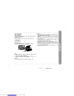
Page 15: ...switch the display brightness by pressing the DIMMER but ton on the remote control Opening and closing the CD compartment The CD compartment cover is motorized When the power is turned on you can open or close the CD com partment cover by pressing the OPEN CLOSE button Caution z Do not stop or move the CD compartment cover manually It may cause malfunctions to the unit z Be careful not to jam your...

Page 16: ...ASS or button to adjust the bass Adjusting the treble Main unit operation 1 Press the BASS TREBLE button until TRE appears on the dis play 2 Within 5 seconds press the VOLUME or button to adjust the treble Remote control operation Press the TREBLE or button to adjust the treble Setting the surround Press the SURROUND button to allow you to enjoy music that seems to surround you SURROUND will appea...

Page 17: ...ress the PRESET or button to select 12 hour or 24 hour display and then press the MEMORY button AM 12 00 The 12 hour display will appear AM 12 00 PM 11 59 0 00 The 24 hour display will appear 0 00 23 59 Note that this can only be set when the unit is first installed or it has been reset Refer to step 3 under If trouble occurs on page 30 3 Within 1 minute press the PRESET or button to adjust the ho...

Page 18: ... button 3 Press the OPEN CLOSE button to open the CD com partment 4 Place a CD on the spindle label side up Be sure to place 3 8 cm disc in the middle of a disc holder 5 Press the OPEN CLOSE button to close the CD com partment Total number of tracks Total playing time 6 Press the button to start playback from track 1 When the last track on the disc has finished playing the CD player will stop auto...

Page 19: ...omatically After use Press the POWER button to enter the power stand by mode Caution z Do not stop or move the CD compartment cover manually It may cause malfunctions to the unit z Be careful not to jam your fingers in the CD compartment cover z If the power fails while the compartment is open wait until the power is restored z If a disc is damaged dirty or loaded upside down NO DISC or READ ERR w...

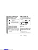
Page 20: ...k selected next by the random operation On the other hand the button does not allow you to move to the previous track The beginning of the track being played will be located Caution After performing repeat or random play be sure to press the but ton Otherwise the disc will play continuously To cancel repeat or random play Press the RANDOM REPEAT button on the remote control repeat edly to select t...

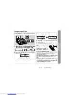
Page 21: ... the pro grammed sequence z Even if you press the POWER button to enter the stand by mode or the function is changed from CD to some other function the programmed selections will not be cleared z During program operation random play is not possible 1 While in the stop mode press the MEMORY SET MEM ORY button to enter the programming save mode 2 Within 30 seconds press the or button to select the d...

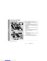
Page 22: ...ual tuning Press the TUNING button as many times as required to tune in to the desired station Auto tuning When the TUNING button is pressed for more than 0 5 sec onds scanning will start automatically and the tuner will stop at the first receivable broadcast station Notes z This can be operated by pressing the TUN or button on the remote control z When radio interference occurs auto scan tuning m...

Page 23: ... ST indicator z will appear when an FM broadcast is in stereo z If the FM reception is weak press the FUNCTION BAND button to extinguish the ST indicator The reception changes to mon aural and the sound becomes clearer After use Press the POWER button to enter the power stand by mode FM stereo mode indicator FM stereo receiving indicator ...

Page 24: ...ions in memory in order starting with preset channel 1 4 Within 5 seconds press the MEMORY SET MEMORY but ton to store that station in memory If the MEMORY and preset number indicators go out before the station is memorized repeat the operation from step 2 5 Repeat steps 1 4 to set other stations or to change a preset station When a new station is stored in memory the station previously memorized ...

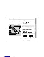
Page 25: ...age 1 Press the CLOCK button to check that the clock is on time 2 Load a disc to be played 1 Press the POWER button to turn the power on 2 Press the CD or TUNER button to select the desired function When you selected the TUNER tune in to the desired sta tion 3 Adjust the volume using the VOLUME buttons Do not turn the volume up too high 4 Press the TIMER button and within 6 seconds press the MEMOR...

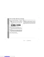
Page 26: ...her unit will not be turned on or off 6 Within 1 minute press the PRESET or button to specify the minutes to start then press the MEMORY button z The timer playback starting time function and volume will be displayed and then the unit will enter the stand by mode au tomatically z will appear and the current time will be displayed To cancel the timer playback Press the POWER button to turn the powe...

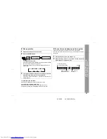
Page 27: ...d sound source 2 Press the SLEEP button To change the sleep time Press the SLEEP button repeatedly to select the desired sleep time The time will decrease as follows The amount of sleep time can also be changed while in the sleep mode 3 Your system will enter the power stand by mode auto matically after the preset time has elapsed The volume will be turned down 1 minute before the sleep op eration...

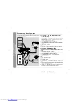
Page 28: ...disconnects the speakers automati cally Adjust the volume using the VOLUME buttons VCR DVD etc MD recorder Connection cable for digital recording White White RCA cord Red Red To the line output jack To the optical line input jack Headphones 1 Use a connection cord to connect the VCR DVD etc to the VID EO AUX IN jacks When using video equipment connect the audio output to this unit and the video ou...

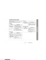
Page 29: ...ones connected z Are the speaker wires disconnected Symptom Possible cause z Playback does not start z Is the disc loaded upside down z Playback stops in the middle or is not per formed properly z Does the disc satisfy the standards z Is the disc distorted or scratched z Playback sounds are skipped or stopped in the middle of a track z Is the unit located near excessive vi brations z Is the disc v...

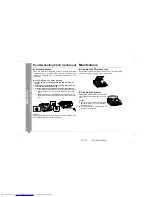
Page 30: ...the pickup clean it gently with a dry cotton swab Cleaning the cabinet 1 Set the unit to the stand by mode and turn the power on again 2 If the unit is not restored in step 1 unplug and plug in the unit and then turn the power on 3 If neither step 1 nor 2 restores the unit do the following Press the POWER button to enter the power stand by mode Unplug the AC power cord from the AC INPUT jack on th...

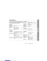
Page 31: ...0 kg Output power 16 watts minimum RMS per channel into 6 ohms from 100 Hz to 20 kHz 10 total har monic distortion Output terminals Speakers 6 ohms Headphones 16 50 ohms recommended 32 ohms CD digital output optical Subwoofer Audio signal 500 mV 47 ko hms Input terminals Video Auxiliary audio signal 500 mV 47 kohms Type Compact disc player Signal readout Non contact 3 beam semiconductor laser pick...

Page 32: ...p The warranties described herein shall be the sole and exclusive warranties granted by Sharp and shall be the sole and exclusive remedy available to the purchaser Correction of defects in the manner and for the period of time described herein shall constitute complete fulfillment of all liabilities and responsibilities of Sharp to the purchaser with respect to the Product and shall constitute ful...

Reviews: