background image

CD-PC3500

– 18 –

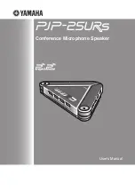
 Figure 18 BLOCK DIAGRAM (2/3)

VOLUME

JOB

VR701

FM

ANTENNA

AM LOOP

ANTENNA

1

2

3

CNP301

Q706

+4B

+4B

M

Q704
Q705

IC701
54PIN

IC701
53PIN

IC701
56PIN

IC701
55PIN

MM1

TAPE

MOTOR

SOLM1,SOLM2

SOLENOID

SWM2

T2 PLAY

SWM1

T1 PLAY

SWM4

R. PLAY

SWM3

F. PLAY

MOTOR
DRIVER

4

5

9

21

16

21

1 2

24

23

15

20

22

15

14

15

12 

7 9

11

9

10

GND 

AM  IF 

FM  IN 

IC302

LC72131

PLL (TUNER) 

OSC 

AM IF 

AM MIX

AM

IN

AM OSC IN

AM  RF  IN

X352

4.5MHz

FMOSC 

AM TRACKING 

AM OSC

T351

+B9

+B9

+B9

IC303

LA1832

FM/AM IF MPX.


STEREO

AM  OSC  IN 

VT

DO

DI

CL

CE

24

23


21

20

17

16

10

14

12

13

18

H/N 

T1/T2 

R-CH

L-CH

L-CH

R-CH

P.B 

REC 

TAPE  2

TAPE  1

L  NF

L(T1) 

R(T1) 

L(T2) 

R(T2) 

R  NF


POP  REDUCE

L  REC 
R  REC 


REC 

P.B.

REC 

ALC 

NOR/

HIGH

T1/T2 

REF 

L  NF
R  NF

PB  HEAD 

REC/PB  HEAD 

SWITCHING 

Q103~Q106 

AC  BIAS 

IC101

AN7345K

PLAYBACK  AND  RECORD

/PLAYBACK  AMP.   

PB

ERASE

HEAD 

SWITCHING

BAIS

Q126

Q124

Q128

L104

Q111

Q110

Q109

Q107

Q108

Q403

Q404

SWITCHING

SWITCHING

SWITCHING

+B5

1

2

3

CNS401

FROM  CD  SECTION

CNP11   

17

+B5

+B9

+B5

+B5

+B5

VOLTAGE

REGURATER  

9

1

3
8

8

7

10

14

2
9
4

11

16

10
15
11

14

12
13

8

17

18

7

1

2

75

74

34

21

69

25

38

35

37

36

3

IC401

LC75341M

AUDIO  PROCESSOR

IC201

BU4066BH

SWITCHING

R

R

R

R

R

R

R

TUNER 

R

VIDEO 

TAPE

CD

BAIS

T1/T2 

REC 

MUTING

Q503

Q504

+B5

21

4

9

Q401

Q402

Q501

Q502

ZD801 

2 3  4  5  7 

Q302

FM  IF  IN

FM  IF 

FM RF 

FM

OSC 

T302

FM  OSC

FM  B.P.F

IC301

TA7358AP

FM  FRONT  END

T301

L312

OSC BUFF

BF301

FM

Q360

FM  +B 

VOLTAGE

REGULATOR

CF303

FM+B MO/ST

FM/AM 

BIAS

OCS

15

19

24 1

2

23

MONO/ST

JK201

VIDEO IN

T331

T306

CF352

TAPE

MECHANISM

+B7

IC501
M62464FP
DOLBY PRO LOGIC
DECORD

CL

DI

CE

Summary of Contents for CD-PC3500

Page 1: ...F THE SET FOR U S A ONLY CD PC3500 In the interests of user safety the set should be restored to its original condition and only parts identical to those specified be used SERVICE MANUAL This document has been published to be used for after sales service only The contents are subject to change without notice SHARP CORPORATION CD PC3500 Mini Component System consisting of PC3500 main unit CP C3500 ...

Page 2: ...outlet Using two clip leads connect a 1 5k ohm 10 watt resistor paralleled by a 0 15µF capacitor in series with all exposed metal cabinet parts and a known earth ground such as conduit or electrical ground connected to earth ground Use a VTVM or VOM with 1000 ohm per volt or higher sensitivity to measure the AC voltage drop across the resistor See diagram Connect the resistor connection to all exp...

Page 3: ...kHz Tuner section Frequency range FM 87 5 108 MHz AM 530 1 720 kHz Cassette deck section Frequency response 50 14 000 Hz Normal tape Signal noise ratio 55 dB TAPE 1 playback 50 dB TAPE 2 recording playback Wow and flutter 0 3 WRMS Front speaker section Type 3 way type 5 1 4 13 cm woofer 2 5 cm tweeter and super tweeter Maximum input power 120 W Rated input power 60 W Impedance 6 ohms Dimensions Wi...

Page 4: ...20 CD Track Down Review Button 3 TUNER Preset Down Button 3 TAPE 2 Rewind Button 21 Bypass Button 22 CD Track Up Cue Button 3 TUNER Preset Up Button 3 TAPE 2 Fast Forward Button 23 Normal Button 24 Phantom Button 25 Timer Set Indicator 26 On Stand by Button 27 Clock Button 28 Timer Sleep Button 29 Function Selector Buttons 30 Dimmer Button 31 Volume Control 32 Equalizer Mode Selector Button 33 CD ...

Page 5: ...put Jacks 16 Front Speaker Terminals 17 Center Speaker Terminals 18 Rear Speaker Terminals Front speaker 11 Super Tweeter 12 Tweeter 13 Woofer 14 Bass Reflex Ducts 15 Speaker Wire Center speaker 11 Full Range Speaker 12 Speaker Wire Rear speaker 11 Full Range Speaker 12 Speaker Wire 1 2 3 4 5 6 7 8 1 2 3 4 5 1 2 1 2 CP C3500 GBOXS0036AWM1 GBOXS0037AWM1 ...

Page 6: ...Up Down Buttons CD control section 18 Memory Button 19 Pause Button 10 Stop Button 11 Play Repeat Button 12 Track Down Review Button 13 Clear Button 14 Track Up Cue Button 15 Random Button 16 Disc Skip Button Tape control section 17 TAPE 1 Play Button 18 TAPE 1 2 Stop Button 19 TAPE 2 Play Button 20 TAPE 2 Record Pause Button 21 TAPE 2 Rewind Button 22 TAPE 2 Fast Forward Button 23 Equalizer Mode ...

Page 7: ...r it has been reset see page 21 5 Press the MEMORY SET button 6 Press the TUNING TIME or button to adjust the hour Press the TUNING TIME or button once to advance the time by 1 hour Hold it down to advance continuously When the 12 hour display is selected AM will change auto matically to PM 7 Press the MEMORY SET button 8 Press the TUNING TIME o r button to adjust the minutes Press the TUNING TIME...

Page 8: ...de Cambio entre la conexión de la alimentación y el modo de reserva Remote control Controlador remoto 1 5 1 5 Black Negro Rear speaker Right Altavoz trasero Derecho Rear speaker Left Altavoz trasero Izquierdo Center speaker Altavoz central 3 Listening to a CD Audición de discos CD 4 Listening to a tape Audición de una cinta 5 Listening to the radio Audición de la radio 6 Recording from CDs Grabaci...

Page 9: ...ver L2 x1 12 Disc Tray 1 Turn fully the lock lever in the 9 3 arrow direction 2 While holding the lock lever rotate 10 1 the cam gear until the cam gear rib engages with the clamp lever 3 Push the slide holder backward to 10 5 engage the claw with the groove and remove it in the direction of the arrow M1 x6 13 CD Servo PWB 1 Screw N1 x1 10 6 Note 2 2 Hook N2 x2 3 Socket N3 x4 14 CD Mechanism 1 Hoo...

Page 10: ... x1 CD Player Unit L1 x2 1 3 2 M1 x3 M1 x3 N3 x2 N2 x2 N3 x2 CD Servo PWB CD Player Base N1 x1 ø3x8mm F1 x1 ø3x6mm G1 x2 ø3x10mm F1 x1 ø3x10mm F2 x3 F2 x1 E3 x1 E4 x1 E2 x2 Main PWB Power Supply PWB Power Supply PWB H1 x14 ø3x10mm H2 x1 J1 x5 ø3x10mm K1 x1 ø3x10mm F3 x1 Display PWB Headphones PWB Open Cassette Holder Tape Mechanism ...

Page 11: ...r 1 Screw B1 x4 11 2 4 Tweeter 1 Screw C1 x2 11 2 5 Super Tweeter 1 Screw D1 x2 11 2 STEP REMOVAL PROCEDURE FIGURE CP C3500 Figure 11 2 Figure 11 1 P2 x3 P1 x1 Q1 x5 P1 x1 Loading Motor PWB CD Mechanism Screw Driver Woofer A1 x1 B1 x4 Ø4x12mm C1 x2 Ø3x10mm D1 x2 Ø3x10mm ...

Page 12: ...ection of the arrow A and remove the pinch roller C1 upwards Note When installing the pinch roller pay attention to the spring mounting position How to remove the belt TAPE 1 See Fig 12 4 1 Remove the main belt D1 x 1 pc from the motor side 2 Remove the FF REW belt D2 x 1 pc How to remove the belt TAPE 2 See Fig 12 4 1 Remove the main belt E1 x 1 pc from the motor side 2 Remove the FF REW belt E2 ...

Page 13: ...the front end of connector so as to protect the optical pickup from electrostatic damage A1 x2 A1 x1 Loading Motor CD Base A1 x2 B1 x2 ø2 6 x6mm Shaft B2 x1 Stop Washer B3 x1 Gear B4 x1 CD Mechanism Pickup ADJUSTMENT MECHANISM SECTION Driving Force Check Torque Meter Specified Value Play TW 2111 Tape 1 Over 80 g Tape 2 Over 80 g Torque Check Torque Meter Tape 2 Play TW 2111 30 to 80 g cm 30 to 80 ...

Page 14: ...oning Low High 0203 Open Close SW not functioning High Low Error during skip operation 0302 Pickup in SW is not detected 0306 During Disc 1 search Open Close SW or Clamp SW or Disc SW do not change to low 0307 Clamp SW not function Low High 0308 Clamp SW not function High Low Since this CD system incorporates the following automatic adjustment functions readjustment is not needed when replacing th...

Page 15: ... output period 2 sec In this case the following indication appears repeatedly TEST L ch R ch S ch Outline Namely two speakers are connected in parallel to one amplifier In the Pro Logic BYPASS mode the amplifier for C ch center channel and the amplifier for S ch surround channel are in MUTE state The SP output is cut In the normal mode of Pro Logic ON mode the amplifiers for C ch and S ch are in o...

Page 16: ...or without such a symbol is microfarad As to electrolyticcapacitor theexpression capacitance withstand voltage is used CH TH RH UJ Temperature compensation ML Mylar type P P Polypropylene type Schematic diagram and Wiring Side of P W Board for this model are subject to change for improvement without prior notice REF NO DESCRIPTION POSITION POSITION SW713 TUNING ON OFF SW714 DIMMER ON OFF SW715 X B...

Page 17: ...IVER IC1 LA9235M SERVO AMP TO MAIN SECTION TO IC601 R CH L CH AGND DGND B6 5V RCHO RVSS LVSS LCHO IC2 LC78641E SERVO SIGNAL CONTROL M SW1 OPEN CLOSE XL1 16 9344MHz 6 5 4 3 3 2 5 4 1 1 2 3 4 7 8 2 1 7 8 9 10 1 2 4 3 5 SW2 CLAMP SW3 DISC NUMBER M3 T T UP DOWN MOTOR 6 1 2 4 3 5 6 1 2 4 3 5 6 75 76 45 46 47 48 32 31 30 65 66 67 68 69 70 71 72 CE CL DI DO INT WRQ RES DEF 52 51 XOUT XIN 73 5 18 36 44 49...

Page 18: ...P B REC ALC NOR HIGH T1 T2 REF L NF R NF PB HEAD REC PB HEAD SWITCHING Q103 Q106 AC BIAS IC101 AN7345K PLAYBACK AND RECORD PLAYBACK AMP PB ERASE HEAD SWITCHING BAIS Q126 Q124 Q128 L104 Q111 Q110 Q109 Q107 Q108 Q403 Q404 SWITCHING SWITCHING SWITCHING B5 1 2 3 CNS401 FROM CD SECTION CNP11 17 B5 B9 B5 B5 B5 VOLTAGE REGURATER 9 1 3 8 8 7 10 14 2 9 4 11 16 10 15 11 14 12 13 8 17 18 7 1 2 75 74 34 21 69...

Page 19: ...RMER RL801 AC POWER SUPPLY CORD AC 120V 60Hz PT802 POWER TRONSFORMER Q803 B8 IS 2 B5 D801 D802 D803 D806 Q804 D807 D809 D818 2 3 1 4 8 B7 B4 B1 RX701 Q701 Q702 Q703 Q710 Q711 Q712 9 8 7 10 7 10 L OUT IC901 STK402 071 POWER AMP IC902 STK402 030 POWER AMP B1 B3 B1 L L L R R R 9 13 5 1 4 8 7 3 8 B2 B2 R OUT Q401 Q402 ZD801 B5 B3 15V B4 M 10V B6 B2 A 10V CD 5V UNSW 5V SW 5V VOLTAGE REGULATOR VOLTAGE R...

Page 20: ... TR 1 2 3 4 5 6 7 8 8 3 6 7 1 4 5 2 PICKUP UNIT GND D PUIN SP SP SL SL 3 2 5 1 4 6 2 3 5 1 4 6 3 6 1 4 5 2 2 3 5 1 4 6 CD MOTOR PWB D 21 20 19 18 17 16 15 14 13 12 11 10 9 8 7 6 5 4 3 2 1 SLDO FDO TDO MUTE Vref STANDBY VCC1 SL SL GND TR TR FO FO FO FD TO B B B B B B M M R54 68K R53 68K R52 68K R51 68K CNP1 R56 68K R55 68K C6 100 10 C54 47 10 C55 0 01 C51 47 10 C53 0 001 R25 10K C7 10 16 C8 0 1 R47...

Page 21: ...T CONTROL A D SW D A B B 5 4 3 2 1 PCKIST VVDD VVSS PD02 PD01 73 80 79 78 77 76 75 74 FRAME SYNC DEFECT PROTECT EFM DECODE CLV CONTROL GENERAL SLICE LEVEL CONTROL PLL VCEC SLCO SLCIST HFL FR VDD5V CONT7 CONT6 VSS V vP FSEQ DEFECT EFMO RES DEF O C DISC_NO B 72 71 70 69 68 67 66 65 11 10 9 8 7 6 24 23 22 21 20 19 18 17 16 15 14 13 12 B 1 2 3 4 5 6 6 5 4 3 2 1 5 4 3 2 1 M 6 L CH B B 46 45 44 43 42 B ...

Page 22: ...330P C111 330P R117 1K C114 330P C112 330P R118 1K C120 560P R122 100K C118 0 033 25 R120 56 C116 100 25 R174 150 C153 100 16 Q110 KRC104 M R115 4 7K Q111 KRC104 M R112 15K R102 1K R101 1K C108 1000P R108 47K Q108 KTC3199 GR R110 4 7K C107 1000P Q107 KTC3199 GR R107 47K R109 4 7K R111 15K Q103 SC1845 F R103 2 2K R105 3 3K C105 180P Q105 SC1845 F R106 3 3K Q106 SC1845 F C106 180P R104 2 2K Q104 SC1...

Page 23: ... 047 C150 8200P C151 0 039 Q126 KRC104 M R164 4 7K R162 47K Q124 KTA1266 GR R158 220 D101 1SS133 D102 1SS133 C146 220 10 C145 22 25 R181 220K Q121 KTC3199 GR R153 10K R154 10K Q122 KTC3199 GR R182 220K R146 10K C142 47 25 C140 3300P C136 0 022 R142 100 R140 1 5K C132 270P R136 3 9K R134 68K C134 22 25 C133 22 25 C141 47 25 R141 100 C131 270P R137 6 8K C135 0 022 R145 10K C139 3300P R139 1 5K R135 ...

Page 24: ... 47K C4 0 R404 3 9K C424 1 50 R409 3 9K R414 3 9K R412 3 9K Q401 KTC3199 GR Q504 KTC3199 GR R524 2 2K C554 0 001 C553 0 001 Q503 KTC3199 GR R523 2 2K C423 2 2 25 R401 22K R221 1K R220 1K BI401 CNS401 CNP11 C558 10 16 R537 1 5K C562 0 082 R536 6 8K C566 0 15 C560 100P C563 47 16 R539 12K R532 27K C561 0 15 R544 220K R543 220K C564 0 047 C565 47 16 R540 100K R542 100K C559 100P R534 3 9K R531 100K I...

Page 25: ...0K IC601 KIA4558P OPA AMP R606 2 2M D603 DS1SS133 R604 47K R603 470K C604 0 0068 R608 2 2M R615 220K C609 0 022 R619 470K C610 0 022 R617 150K IC602 KIA4558P OPA AMP R616 220K R618 150K C612 0 022 C607 0 022 ZD601 DZ6 2BSC C619 47 25 C608 0 022 C613 0 0027 R627 390K C617 2 2 50 R629 100K D604 DS1SS133 D605 DS1SS133 C618 2 2 50 R630 100K R628 390K C616 0 0027 D606 DS1SS133 R626 220K IC603 KIA4558P ...

Page 26: ...58AP FM FRONTEND C303 10P C304 0 01 C305 4 7P CH R302 10 C306 0 022 C307 10 16 C324 3 9P UJ C311 18P C310 15P CH VD303 KDV147B 1T R309 10K C313 22P CH T302 1 3 2 T301 C312 0 022 CF303 FM IF VD302 KDV147B 1T C309 0 001 C308 4 7P CH D305 1SS133 L312 R311 100K R313 33K R314 22 1 6W C317 0 001 C316 0 022 C315 0 0047 C314 0 0047 C301 0 001 D303 1SS133 D304 1SS133 CNP301 R316 4 7K C318 100P Q302 KTC3194...

Page 27: ... 01 R379 2 2K R380 1 5K C393 1 50 C380 10 16 R381 10K L351 100µH R377 47K C387 0 022 C392 0 001 C394 47 16 C397 0 022 IC302 LC72131 PLL TUNER T351 C351 0 022 C350 0 022 CF352 AM IF R352 1K C353 0 022 R393 1K C354 0 022 CF351 FM IF R353 270 C356 0 001 C399 0 022 C398 100 10 C355 22P C357 2 2 50 R355 3 3K C358 1 50 C370 1 50 R388 3 9K R387 1 2K L352 100µH ZD351 MTZJ5 1B C396 100 10 C395 0 022 R392 2...

Page 28: ...04 G03 G02 G01 G12 G13 G14 G15 P1 P2 P3 P4 P5 P6 P7 P8 P9 P10 P11 P12 P13 P14 P15 P16 P17 P18 CD CLAM SW KEYIN0 KEYIN2 8 9 7 5 4 3 2 3 6 5 2 1 6 4 8 9 7 1 1 23 22 21 18 2 20 19 17 16 15 14 13 12 11 10 9 8 7 6 5 4 3 56 55 54 53 52 51 50 49 48 47 44 43 42 41 40 39 38 37 36 35 34 33 32 31 30 29 28 27 26 25 24 23 16 15 14 13 12 11 10 9 8 7 6 2 4 1 3 5 6 7 8 9 10 11 12 13 13 12 11 10 9 8 7 2 1 3 4 5 6 ...

Page 29: ... 4 8 18 17 16 15 14 13 12 11 10 8 7 6 5 4 3 2 1 33 32 31 30 29 28 27 26 25 24 23 16 15 14 13 12 11 10 9 8 7 6 3 2 1 CNP12 DISPLAY PWB A2 RS708 10K RS709 10K RS710 10K C724 0 022 C723 47 16 IC702 BU2092F EXPANDER C725 47 16 C726 0 022 RS723 1K LED718 RS724 10K RS725 10K RS726 10K LED709 LED710 LED708 RS720 220 RS721 1K LED706 LED707 RS722 1K IC703 BU2092F EXPANDER SW732 OPEN CLOSE SW731 DISC SKIP R...

Page 30: ...C930 47P R932 1K C932 47 50 R930 22K IC902 STK402 030 POWER AMP R918 56K Q904 KTC3199 GR R917 1K C913 47 50 R920 56K R919 56K C937 220P R940 68K C936 100 50 C935 100 50 R924 4 7 1 4 R923 4 7 1 4 C921 0 1 ML C920 0 1 ML C919 0 1 ML C918 0 1 ML C804 2200 50 R803 22K C803 2200 50 R801 820 ZD803 DZ130BSB C802 220 25 R805 3 3 1 2W R807 33 Q823 KTD2026 Y C807 22 25 R804 22K C806 0 047 ML IC802 KIA7810AP...

Page 31: ...1K F805 2A 250V C834 47 50 C828 220 50 D807 1N4004S F804 4A 125V C820 0 047 ML C827 220 50 D808 1N4004S D818 1N4004S D809 1N4004S C826 220 50 Q804 KTA1274 Y R813 10 R814 2 2K R812 47K C825 47 50 ZD802 DZ300BSB C821 0 047 ML D805 1N4004S D806 1N4004S D804 4004S 803 4004S D802 3SBA60F C819 0 047 ML F803 4A 125V F802 5A 125V C818 0 047 ML C817 0 047 ML F801 5A 125V D801 TS6B04GM 10 K 816 00 50 R959 4...

Page 32: ...3 C559 R534 R540 C570 C333 C338 C330 C323 C303 C315 C306 R381 C301 R378 R374 R372 C384 R373 R388 C382 R376 R359 C381 R360 R379 C386 C392 R377 C397 R385 R380 C318 C385 R393 R383 R325 C324 R327 R322 C311 R302 C313 C310 C351 C312 C354 C350 R353 R352 C399 C308 C314 R311 C344 C366 R351 R313 C317 C316 R316 R365 C369 C334 C361 R336 C336 R323 C342 C332 C363 C335 C512 C518 C513 R542 C521 R539 R512 C519 R22...

Page 33: ...529 C551 R406 R407 C554 C553 R408 R402 R153 R403 R135 R131 C123 C419 R404 R125 R123 C119 C404 R121 C415 R409 C102 C101 R114 R113 R164 R162 R115 R109 R110 R107 R108 R167 C106 C108 R166 R106 R112 C107 R104 C105 R103 R102 R105 R101 C113 C114 R122 C120 R124 C111 C127 C131 R134 R137 C132 R126 R139 R138 R136 C139 R141 C140 R145 R146 R142 R154 R140 C610 R617 C608 R615 C607 C612 R611 R618 C611 R616 R621 R...

Page 34: ...W720 POWER D708 R796 IC704 D711 D712 BI701 CNP701 LED700 LED707 LED706 LED704 LED705 LED711 LED714 LED718 LED71 LED71 L SW708 STOP SW705 REV SW705 RD25 SW701 CD SW702 TAPE SW721 CLOCK RD09 R RD23 RD24 C721 C718 C719 IC701 R726 C716 R711 RD21 RD22 RD04 R735 RD02 RD11 RD01 RD12 R749 RD18 R790 C714 C711 R794 R793 1 5 10 15 20 25 35 40 45 50 51 55 60 65 70 75 80 81 85 90 95 100 30 31 CNS701 1 10 2 3 4...

Page 35: ...15 R704 R705 R706 R729 718 LED712 LED713 LED701 LED702 LED708 LED709 LED710 SW729 DISC2 SW731 DISC SKIP SW717 NORMAL SW705 RD25 R783 R721 R722 R725 R784 R779 R781 R785 R743 R776 RD27 R786 R787 R782 R744 IC702 C726 C710 C709 IC703 R747 R746 C724 R707 R703 R702 R701 RM712 RM711 RM710 R772 R771 RD13 R770 R769 R768 R766 R764 R762 R761 R763 R765 R767 RS708 RD14 RD07 RD17 RD24 RD26 1 1 5 5 9 9 10 10 18 ...

Page 36: ...7 C941 D905 R941 C944 C940 IC902 R948 C943 C939 R945 R931 R951 C934 R935 R930 C946 C932 R949 C930 R934 R936 Q905 C938 R938 Q907 D904 D906 Q908 LUG902 R801 C801 ZD803 C802 C961 R974 R972 Q910 R973 D909 R933 C931 R932 R937 C935 C933 R939 C945 C937 C936 R940 R946 R947 R954 R955 R971 R970 C949 R921 C915 C914 RL901 R901 C903 C902 R903 R902 D908 C917 R922 C910 R917 R914 C916 R915 C912 RL90 CNP805 F801 5...

Page 37: ...R956 R957 C986 L903 L904 F801 5A 125V C831 SO901 SPEAKER TERMINAL REAR L CH REAR R CH FRONT L CH FRONT R CH CENTER 1 2 RD CNS806 BR 1 2 M901 FAN MOTOR CNS801 P39 8 E TO POWER TRASFORMER AC POWER SUPPLY CORD AC 120V 60Hz BLACK WHITE PT802 POWER TRANSFORMER 1 2 E E B C E C B C B 15 14 13 12 11 0 5 4 3 2 1 CNP601 L601 JK601 HEADPHONES C698 C699 BR COLOR TABLE RD R OR YL GR BL VL GY WH W BK PK BROWN R...

Page 38: ...PK WH YL BK BK PK WH 1 2 3 4 5 6 7 8 1 2 3 4 5 6 7 8 1 2 3 4 5 6 7 3 4 1 2 5 6 7 PICKUP UNIT 306 CD SERVO PWB C CD MOTOR PWB D DIGITAL OUT PWB A4 SW4 PICKUP IN M2 SLED MOTOR 1 2 3 4 5 6 1 2 3 4 5 6 1 2 3 4 5 6 CNP3A E C B B C E 1 2 3 IC2 IC3 R48 C46 R21 R40 R45 R22 R46 R95 R94 C30 R82 C40 R84 R81 C43 R83 C80 R12 C23 R79 R13 C21 C81 R11 C25 R14 R87 C22 R10 C20 R8 C27 C42 C26 R15 C82 C29 R4 R3 R54 R...

Page 39: ...Y P35 10 H TO DISPLAY PWB BR COLOR TABLE RD R OR YL GR BL VL GY WH W BK PK BROWN RED ORANGE YELLOW GREEN BLUE VIOLET GRAY WHITE BLACK PINK 1 2 3 5 4 3 8 7 6 2 1 WH BK WH RD BL RD OL OL BR BK BR CNS802 CNS804 PT801 POWER TRANSFORMER RD BL CNS801 CNP801 P37 10 G TO POWER SUPPLY PWB CNP804 P36 5 H TO POWER SUPPLY PWB CNP802 P36 4 H TO POWER SUPPLY PWB 2 1 1 2 3 6 5 4 3 2 1 TAPE 1 PLAYBACK HEAD TAPE 2...

Page 40: ...2 31 PIN NO VOLTAGE 51 64 63 62 61 60 59 58 57 56 55 54 53 52 3 4V 0V 0V 3 2V 0V 0V 0V 0V 0V 4 8V 4 9V 4 9V 4 6V 0V 4 9V 0V 68 67 66 65 69 80 79 78 77 76 75 74 73 72 71 70 IC2 4 6V 4 6V 4 6V 4 6V 4 6V 0V 2 6V 0V 4 6V 4 8V 0V 0V 0V 3 9V 4 8V 4 7V 2 7V 3 9V 4 9V 4 9V 4 9V 4 4V 4 6V 4 4V 4 2V 4 5V 4 3V 4 9V 4 9V 3 9V 2 7V 4 9V 2 7V 0V 0V 4 8V 0V 0V 4 7V 2 8V 2 6V 2 6V 2 6V 2 6V 0 6V 0 6V 2 6V 2 6V 2 ...

Page 41: ...MAL Type EDGE CH2 Delay 2 924ms Hold off 0 2us CH3 0 00V CH4 0 00V BW FULL Trigger Filter Offset 1 IC2 24 6 IC2 25 T FDO PDO2 PDO1 Stopped CH1 500mV DC 10 1 CH3 1V DC 10 1 CH4 1V DC 10 1 500ms div 500ms div NORM 20kS s 1 4 3 Record Length Smoothing ON CH1 0 000V CH2 0 0V Main 100K Zoom 2K Mode AUTO Type EDGE CH2 Delay 0 0ns Hold off 0 2us CH3 0 00V CH4 0 00V BW FULL Trigger Filter Offset CH1 v DIV...

Page 42: ...D disc tray with the brush side down then press the play button You will hear music for about 20 seconds and the CD player will automatically stop If it continuous to tum press the stop button 1 2 3 The CD lens cleaner should be effective for 30 50 operations however if the brushes become worn out earlier then please the cleaner disc If the CD cleaner brushes become very wet then wipe off any exce...

Page 43: ...ithout inserting a disc and try starting the playback operation 2 Does the focus lens move up and down Waveform drawing 43 1 Check the focus peripheral circuit 3 Is the laser lit Spindle motor M1 4 Is the turntable rotating Figure 43 2 Figure 43 3 Yes Yes Yes No No No No No No No Yes Yes No T FDO TDO Stopped CH1 500mV DC 10 1 CH3 500mV DC 10 1 500ms div 500ms div NORM 20kS s 1 3 Record Length Smoo...

Page 44: ...nd then try starting the play operation 3 Spin system check The spin driver circuit is OK 1 The turntable rotates a little Waveform drawing 44 2 Check around pin 25 on IC2 pins 15 and 16 on IC3 and CNS3A B 2 The turntable doesn t rotate T T TE DRF Stopped CH1 10V DC 10 1 CH2 1V DC 10 1 100ms div 100ms div NORM 100kS s 2 1 Record Length Smoothing ON CH1 0 0V CH2 0 00V Main 100K Zoom 2K Mode NORMAL ...

Page 45: ...rm is normal but the TOC data cannot be read Check the PDO waveform Figure 45 1 Check around pins 1 6 on IC2 Figure 45 1 Figure 45 2 T FDO PDO2 PDO1 Stopped CH1 500mV DC 10 1 CH3 1V DC 10 1 CH4 1V DC 10 1 500ms div 500ms div NORM 20kS s 1 4 3 Record Length Smoothing ON CH1 0 000V CH2 0 0V Main 100K Zoom 2K Mode AUTO Type EDGE CH2 Delay 0 0ns Hold off 0 2us CH3 0 00V CH4 0 00V BW FULL Trigger Filte...

Page 46: ...1 FE 22 RFEV 28 RF 1 PDO1 2 PDO2 3 VVSS 4 PCKIST 5 VVDD 6 FR 7 HFL 8 SLCIST 9 SLCO 10 EFMIN 11 JITTV 12 JITTC 13 BH 14 PH RFENV 15 FE 16 TE 25 SPDO 26 SLDO 27 FG 28 LASER 29 CONT1 30 CONT2 CONT3 CONT4 CONT5 31 32 33 34 PCK 35 C2F 36 VDD 37 DOUT 38 FSX 39 EFLG 40 TEST EFMO DEFECT FSEQ V P CONT7 CONT6 VSS VDD DRF RES WRQ INT DO DI CL CE 17 VREF 18 ADAVDD 19 ADAVSS 20 PHREF 21 BHREF 22 TBLO 23 TDO 24...

Page 47: ... SPDO Output 1 2VDD Output terminal for spindle control D A output 26 SLDO Output 1 2VDD Output terminal for sled control D A output 27 FG Input FG signal input terminal When not used connect to 0V 28 LASER Output L LASER ON OFF control terminal 29 CONT1 In Output Input mode General purpose input output terminal 1 Controlled with serial data command 30 CONT2 In Output Input mode General purpose in...

Page 48: ... 67 DI Input interface Data input terminal 68 DO Output L Data output terminal 69 INT Output H Interruption signal output terminal 70 WRQ Output H Interruption signal output terminal 71 RES Input Reset input terminal of LC78640 When turning on power set it at L 72 DRF Output L Focus ON detection terminal 73 VDD5V Power terminal for microcomputer interface 74 VSS Ground terminal of digital system S...

Page 49: ...2 CLK Output CLOCK OUTPUT 23 P21 DI Output DATA OUTPUT 24 P20 DO Input DATA INPUT 25 AVss AVSS ANALOG GROUND 26 ANI7 TUN SMIM BUSY Input TUNER SIGNAL METER INPUT 27 ANI6 SPEANA3 Input SPEANA DATA INPUT L R 16 KHz 28 ANI5 SPEANA2 Input SPEANA DATA INPUT L R 63Hz 29 ANI4 SPEANA1 Input SPEANA DATA INPUT R CH 1KHz 30 ANI3 SPEANA0 Input SPEANA DATA INPUT L CH 1KHz 31 33 ANI2 ANI0 KEY2 KEY0 Input KEY IN...

Page 50: ...mputer IX0332AW 2 2 Port Name Terminal Name Pin No Input Output In this unit the terminal with asterisk mark is open terminal which is not connected to the outside Function 1 IN2 CH2 inverted input 2 IN1A CH1 inverted input 3 IN1B CH1 output offset control 4 OUT1 CH1 inverted output 5 OUT1 CH1 non inverted output 6 OUT2 CH2 inverted output 7 OUT2 CH2 non inverted output 8 14 GND GND 15 OUT3 CH3 no...

Page 51: ...ef CONTROL CIRCUIT CONTROL CIRCUIT CONTROL CIRCUIT LOUT LBASS 0 1uF LIN LSEL0 L4 L3 L2 L1 R1 R2 R3 R4 RSEL0 R1N RTRE LTRE RBASS 0 1uF ROUT Yref VDD CL DI CE YSS CCB INTERFACE CD Tuner Tape Video 24 23 22 21 20 19 18 17 16 15 14 13 1 2 3 4 5 6 7 8 9 10 11 12 LC75341 DI CE VSS LOUT LBASS LTRE LIN LSEL0 L4 L3 L2 L1 CL VDD VREF ROUT RBASS RTRB RIN RSEL0 R4 R3 R2 R1 ...

Page 52: ...53 52 51 50 38 49 48 47 46 45 44 43 42 41 40 39 37 36 35 34 33 32 31 20 19 18 17 16 15 14 13 12 11 10 9 8 7 6 5 4 3 2 1 30 29 28 27 26 25 24 23 22 21 PIN NO PIN NO PIN NO CONNECTION CONNECTION CONNECTION 10G 11G 12G 13G 14G 15G 9G 8G 7G 6G 5G 4G 3G 2G P10 P11 P12 P9 P8 P7 P6 P5 P4 P3 P20 P21 P22 P23 P24 P25 P19 P18 P17 P16 P15 P14 P13 P2 1G F2 F2 F2 NP NP NP NP F1 F1 F1 NX NX NX NX NX NX NX NX P1 ...

Page 53: ...indrical type without lead wire VC TV Square type without lead wire VC TQ Square type without lead wire VC CY Square type without lead wire VC CZ Square type without lead wire VC J The 13th character represents capacity difference J 5 K 10 M 20 N 30 C 0 25 pF D 0 5 pF Z 80 20 If there are no indications for the electrolytic capacitors error is 20 Resistors VRD Carbon film type VRS Carbon film type...

Page 54: ...1 J AA Silicon DS1SS133 D708 714 VHDDS1SS133 1 J AA Silicon DS1SS133 D717 718 VHDDS1SS133 1 J AA Silicon DS1SS133 D801 VHDTS6B04GM 1 J AP Silicon TS6B04GM 1 D802 VHDD3SBA60F 1 J AA Silicon DS3SBA60F D803 809 VHD1N4004S 1 J AB Silicon 1N4004S D810 813 VHDDS1SS133 1 J AB Silicon DS1SS133 D814 818 VHD1N4004S 1 J AB Silicon 1N4004S D901 909 VHDDS1SS133 1 J AB Silicon DS1SS133 LED700 VHP4204SRT7 1 J AD...

Page 55: ... AA 0 022 µF 25V C362 RC GZA335AF1H J AB 3 3 µF 50V Electrolytic C363 VCTYMN1EF223Z J AA 0 022 µF 25V C364 RC GZA106AF1C J AB 10 µF 16V Electrolytic C365 VCTYPA1CX223K J AA 0 022 µF 16V C366 VCKYMN1HB102K J AA 0 001 µF 50V C367 368 RC GZA105AF1H J AB 1 µF 50V Electrolytic C369 VCCSBT1HL270J J AA 27 pF 50V C370 372 RC GZA105AF1H J AB 1 µF 50V Electrolytic C373 374 VCTYPA1CX153K J AA 0 015 µF 16V C3...

Page 56: ...6 VCEAZA1HW105M J AB 1 µF 50V Electrolytic C917 VCCSPA1HL221J J AA 220 pF 50V C918 921 VCCSMF1HL104J J 0 1 µF 50V C930 VCCSMF1HL470J J AA 47 pF 50V C931 VCCSMF1HL150J J AA 15 pF 50V C932 933 VCEAZA1HW476M J AB 47 µF 50V Electrolytic C934 VCCSMF1HL221J J AA 220 pF 50V C935 936 VCEAZA1HW107M J AC 100 µF 50V Electrolytic C937 VCCSMF1HL221J J AA 220 pF 50V C938 VCCSMF1HL223J J 0 022 µF 50V C939 940 VC...

Page 57: ... AA 22 kohms 1 8W R526 VRD MN2BD473J J AA 47 kohms 1 8W R527 VRD ST2CD473J J AA 47 kohms 1 6W R528 VRD MN2BD223J J AA 22 kohms 1 8W R529 VRD MN2BD473J J AA 47 kohms 1 8W R530 VRD MN2BD331J J AA 330 ohms 1 8W R531 VRD MN2BD104J J AA 100 kohm 1 8W R532 VRD MN2BD273J J AA 27 kohms 1 8W R533 VRD MN2BD153J J AA 15 kohms 1 8W R534 VRD MN2BD392J J AA 3 9 kohms 1 8W R535 VRD MN2BD273J J AA 27 kohms 1 8W R...

Page 58: ...W710 92LSWICH1401AT J AC Switch Key Type REC SW711 92LSWICH1401AT J AC Switch Key Type TUNING UP SW712 92LSWICH1401AT J AC Switch Key Type VIDEO SW713 92LSWICH1401AT J AC Switch Key Type TUNING 5 R811 VRD ST2CD123J J AA 12 kohms 1 6W R812 VRD ST2CD473J J AA 47 kohms 1 6W R813 VRD ST2CD100J J AA 10 ohm 1 6W R814 VRD ST2CD222J J AA 2 2 kohms 1 6W R815 VRD ST2CD102J J AA 1 kohm 1 6W R816 VRD ST2CD473...

Page 59: ... Panel Right Not Replacement Item 203 2 PCUSG0022AWZZ J AB Cushion Leg 204 92LCOV3303AASY J CD Tray Cover Ass y 204 1 Cover CD Tray Not Replacement Item 204 2 GCOVA1254AWSA J AE Cover CD Tray Panel Left 204 3 GCOVA1255AWSA J AE Cover CD Tray Panel Right 6 205 GCAB 1184AWSA J AP Top Cabinet 206 GITAR0543AWSA J AN Rear Panel For U S A Central America 206 GITAR0544AWSA J Rear Panel For Mexico 206 GIT...

Page 60: ...chanism PWB F 92LPC99C017 J CD Loading Motor PWB Only OTHER SERVICE PART UDSKA0004AFZZ J AZ CD Optical Pickup Lens Cleaner Disc SPEAKER BOX PARTS CENTER SPEAKER 901 92LSRCNF005RS J Net Frame Ass y 902 92LSRCBC006RS J Bottom Cabinet 903 92LSRCSC005RS J Speaker Cord 904 92SRCSW006RS J Screw ø3 14mm 905 92LSRCPL012RS J Label Parts Code 906 92LSRCFT001RS J Cushion SP1 VSPA010PB146A J Speaker SPEAKER B...

Page 61: ...CD PC3500 7 A B C D E F G H 1 2 3 4 5 6 Figure 8 CD MECHANISM EXPLODED VIEW 8 CD PC3500 306 1 701 304 701 302 301 702 303 M1 703x4 305x2 SW4 M2 305 PWB D 306 2 306 3 306 704 ...

Page 62: ...5 x2 233 608 PT801 601x2 608x2 210 M901 265 201 21 201 10 201 25 201 17 201 14 201 13 201 16 201 28 201 29 201 30 201 27 201 15 201 12 201 26 201 11 201 21 201 1 201 24 PWB A1 614x2 614x2 FL701 214 268 215 Silicon Grease Silicon Grease 211 608 PWB B 211 211 231x10 609x3 226 IC901 IC902 271 270 207 IC802 IC801Q823 213 237 612 606x2 614 604x4 609x4 222 220 209 612 221 606x2 219 208 230 228 607 267 6...

Page 63: ...E F G H 1 2 3 4 5 6 10 CD PC3500 CD MECHANISM 205 257 235 266 243 224 259 239 239 204 2 204 1 204 3 204 239x3 PWB C 239 232 M3 SW3 PWB F 604x2 604x2 SW2 SW1 254 260 242 258 263 616 245 264 248 253 255 252 251 250x4 249 256 262 241 238 247 244 612 246 234 240 ...

Page 64: ...5 6 913x4 910 910 916 909x4 with Capacitor C1 2 C1 2 Capacitor 907 914x2 917 SP1 2 901 905 SUPER TWEETER SP1 L CH SP2 R CH TWEETER SP3 L CH SP4 R CH WOOFER SP5 L CH SP6 R CH SUPER TWEETER SP1 L CH SP2 R CH TWEETER SP3 L CH SP4 R CH WOOFER SP5 L CH SP6 R CH C1 2 Capacitor 2 2 µF 100V Electrolytic N P BK YE BK BK RED RED ...

Page 65: ...CD PC3500 11 A B C D E F G H 1 2 3 4 5 6 Figure 12 SPEAKER EXPLODED VIEW 2 2 12 GBOXS0037AWM1 901 SP1 2 SP1 2 902 904x6 905 903 GBOXS0036AWM1 904x4 902 904x4 906x4 SP1 901 903 905 ...

Page 66: ...C1 Polyethylene Bag Accessories FRONT SIDE OF CENTER REARSPEAKERS FRONT SIDE OF MAIN SET FRONT SIDE OF FRONT SPEAKER 92LSRCPE008RS Polyethylene Bag 92LSRCPE008RS Polyethylene Bag 92LSRCBP011RS Packing Add Bottom 92LSRCTP010RS Packing Add Top A C B B C SPAKC0887AWZZ Packing Case Bar Code Label Center Speaker Rear Speaker L R GBOXS0037AWM1 GBOXS0036AWM1 TOP A 14 PACKING OFF THE SET For U S A Only Se...

Page 67: ...CD PC3500 13 MEMO ...

Page 68: ... electronic mechanical photocopying recording or otherwise without prior written permission of the publisher SHARP CORPORATION Communication Systems Group Quality Reliability Control Center Higashihiroshima Hiroshima 739 0192 Japan Printed in Japan COPYRIGHT 2000 BY SHARP CORPORATION ALL RIGHTS RESERVED SC SL LAG A0002 2627NS HA M ...

Reviews: