


CD-MPS600/CD-MPS66
3 – 6
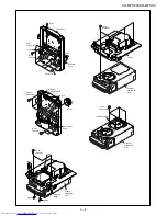
3.2. How to Remove the tray motor/main cam motor/5-
Changer Motor PWB (See Fig. 6)
1. Remove the screws (A1)x 2 pcs., to remove tray motor/main cam
motor/5-Changer Motor PWB.
Figure 6
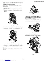
NOTE: There are 2 more screws tighten the motors at the bottom of
main chassis. Before performing procedure 1 above, disc stop
spring, top plate sear up down board and trays must be
removed, then only the 2 screws can be untighten.
5-Changer
Motor PWB
Tray Motor
Changer Mechanism Unit
Main Cam Motor
(A1)x2
φ
2x10mm
Summary of Contents for CD-MPS600
Page 12: ...CD MPS600 CD MPS66 2 7 APPLY GREASE PULL THE LEVER UNITIL REACH THE ARROW MARK 143 112 3 ...
Page 16: ...CD MPS600 CD MPS66 2 11 CHANGE COLOR TO BLACK 150 151 148 7 ...
Page 19: ...CD MPS600 CD MPS66 2 14 10 148 147 146 145 ...
Page 20: ...CD MPS600 CD MPS66 2 15 APPLY GREASE WHEN FIXING ITEM 2 MUST FOLLOW AS SHOWN 121 144 130 11 ...
Page 21: ...CD MPS600 CD MPS66 2 16 FIGURE 1 FIGURE 3 FIGURE 2 APPLY GREASE SC141 APPLY GREASE 117 12 ...
Page 29: ...CD MPS600 CD MPS66 2 24 BIG SLOT FACING OUT 110 20 ...
Page 33: ...CD MPS600 CD MPS66 2 28 804 24 SCREW TORQUE 3 kgf cm 0 5 0 ...
Page 41: ...CD MPS600 CD MPS66 2 36 NO GAP HAVE GAP O K N G 32 ...
Page 55: ...CD MPS600 CD MPS66 5 4 MEMO ...