


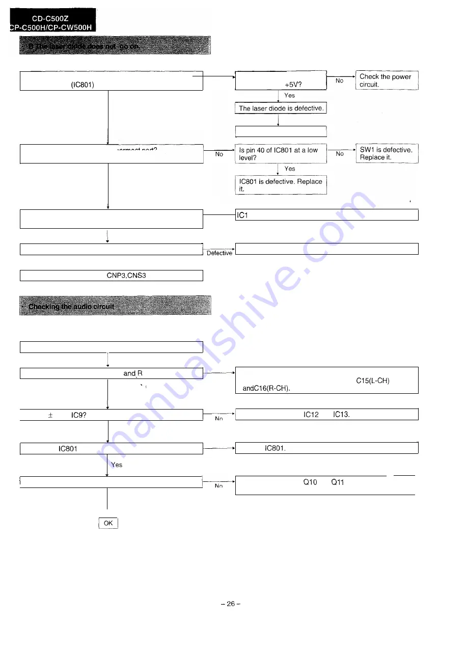
Is the laser control signal of pin 38 (LANF) of the
microcomputer
at a low level?
Is the Q7 laser diode driver
No
emitter voltage
Yes
Replace the optical pickup.
Is the pickup returned to the innermost part?
Is the pickup in switch SW1 turned to ON?
Yes
Check if pins 57 (FEM+) and 58 (FEM-) of ICI are
outputting.
Defective
l
is defective. Replace it.
Normal
Check pin 8 of the slide motor driver (IC5).
Normal
The slide motor driver(lC5) is defective.Repace it.
Check if there is voltage at
and Ml.
Is there audio output?
No
Is there audio output from both L
channels?
Yes
l
Check the muting Transistor, Q6 and Q8 and replace.
No
l
Check the sound coupling capacitors
Is there 5V at
Yes
Check power circuits
and
N
o
Is pin 36 of
muting output at a high level?
Replace
No
Is pin 3 of Q6 and Q8 at a low level?
No
Check the voltage of
and
and replace faulty
parts.
Yes
Summary of Contents for CD-C500Z
Page 7: ...P AY REPEPlT 1 ...
Page 28: ...7 3 I I rt Figure 34 BLOCK DIAGRAM l 2 34 ...
Page 29: ... L ...
Page 30: ...I ...
Page 31: ......
Page 32: ...x iii S I 1 ...
Page 33: ...A B C D E F G H I ...
Page 34: ... IL ...
Page 35: ......
Page 36: ...I e I I ...
Page 37: ...I 5 Y i Y b I a I m 0 I I 1 cl w Y I3 I ...
Page 38: ... I ...
Page 39: ... a m I 0 I a w u cl I I ...
Page 42: ...3 0 2 I 1 1 2 r I 3 4 r Figure 61 CD MECHANISM 5 EXPLODED 6 VIEW I 61 G 62 ...
Page 43: ...A B C D E F G H 3 4 Figure 63 CABINET EXPLODED VIEW 112 63 64 ...
Page 44: ...8 ...