Sharp Carousel R-395N Service Manual Download Page 22

R395N(S)

11 – 5

[13] 1ST. LATCH SWITCH, 2ND. INTERLOCK RELAY CONTROL SWITCH AND MONITOR
SWITCH ADJUSTMENT

1. Adjustment

If the 1st. latch switch, 2nd. interlock relay control switch and monitor
switch do not operate properly due to a misadjustment, the following
adjustment should be made.

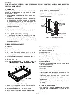
1. Loosen the two (2) screws holding latch hook to the oven cavity

front flange.

2. With door closed, adjust latch hook by moving it back and forth,

and up and down. In and out play of the door allowed by the upper
and lower position of the latch hook should be less than 0.5mm.
The vertical position of the latch hook should be adjusted so that
the 1st.latch switch and 2nd. interlock relay control switch are acti-
vated with the door closed. The horizontal position of the latch hook
should be adjusted so that the plunger of the monitor switch is
pressed with the door closed.

3. Secure the screws with washers firmly.

4. Check all switches operation. If each switch has not activated with

the door closed, loosen screw and adjust the latch hook position.

2. After adjustment, check the following.

1. In and out play of door remains less than 0.5mm when in the

latched position. First check upper position of latch hook, pushing
and pulling upper portion of door toward the oven face. Then check
lower portion of the latch hook, pushing and pulling lower portion of
the door toward the oven face. Both results (play in the door)
should be less than 0.5mm.

2. The 1st. latch switch and 2nd. interlock relay controls witch inter-

rupt the circuit before the door can be opened.

3. Monitor switch contacts close when door is opened.

4. Reinstall outer case and check for microwave leakage around door

with an approved microwave survey meter.(Refer to Microwave
Measurement Procedure.)

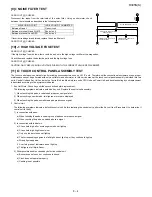
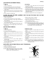
 Figure C-4. Latch Switch Adjustments

[14] DOOR REPLACEMENT

1. REMOVAL

1. Disconnect the power supply cord.

2. Open the door slightly.

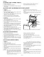
3. Insert a putty knife (thickness of about 0.5mm) into the gap

between the choke cover and door frame as shown in Figure C-5 to
free engaging parts.

4. Pry the choke cover by inserting a putty knife as shown Figure C-5.

5. Release choke cover from door panel.

6. Now choke cover is free.

NOTE:

When carrying out any repair to the door, do not bend or
warp the slit choke (tabs on the door panel assembly) to
prevent microwave leakage.

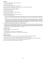
Figure C-5. Door Disassembly

7. Release two (2) pins of door panel from two (2) holes of upper and

lower oven hinges by lifting up.

8. Now, door panel with door frame is free from oven cavity.

9. Remove the one (1) screw holding the door panel to door frame.

10.Release door panel from ten (10) tabs of door frame.

11.Now, door panel with sealer film is free.

12.Tear sealer film from door panel.

13.Now, door panel is free.

14.Slide latch head upward and remove it from door frame with releas-

ing latch spring from door frame and latch head.

15.Now, latch head and latch spring are free.

16.Remove the two (2) door stoppers.

17.Remove door glass from door frame by sliding.

18.Now, door glass is free.

19.Remove the door decorations from the door frame by straightening

all tabs of the door decorations.

20.Now, the door frame is free.

2. REINSTALL

1. Re-install door screen and door decoration to door frame.

2. Reinstall the latch spring to the latch head. Reinstall the latch

spring to the door frame. Reinstall latch head to door frame.

3. Reinstall door panel to door frame by fitting ten (10)tabs of door

frame to ten (10) holes of door panel.

4. Put sealer film on door panel. Refer to “Sealer Film” about how to

handle new one.

5. Catch two (2) pins of door panel on two (2) hole of upper and lower

oven hinges.

6. Re-install choke cover to door panel by pushing.

NOTE:

After any service to the door;

1) Make sure that 1st. latch switch, 2nd. interlock relay control switch

and monitor switch are operating properly. (Refer to chapter “Test
Procedures”.).

Latch Hook

Monitor Switch

2nd. Interlock
Relay Control
Switch

1st Latch Switch

Latch
Heads

Door

Choke Cover

Door Frame

Putty Knife

Summary of Contents for Carousel R-395N

Page 1: ...TIONS FOR USING LEAD FREE SOLDER CHAPTER 11 COMPONENT REPLACEMENT AND ADJUSTMENT PROCEDURE CHAPTER 12 MICROWAVE MEASUREMENT CHAPTER 13 CIRCUIT DIAGRAMS Parts List S2901R395NPJS SERVICE MANUAL R395N S CONTENTS This document has been published to be used for after sales service only The contents are subject to change without notice TopPage MICROWAVE OVEN R 395N S MODEL In the interests of user safet...

Page 2: ...Y TEST 8 4 12 L KEY UNIT MEMBRANE SWITCH TEST 8 5 13 M RELAY TEST 8 5 14 N PROCEDURES TO BE TAKEN WHEN THE FOIL PATTERN ON THE PRINTED WIRING BOARD PWB IS OPEN 8 5 CHAPTER 9 TOUCH CONTROL PANEL ASSEM BLY 1 OUTLINE OF TOUCH CONTROL PAN EL 9 1 2 SERVICING FOR TOUCH CONTROL PANEL 9 1 CHAPTER 10 PRECAUTIONS FOR USING LEAD FREE SOLDER CHAPTER 11 COMPONENT REPLACEMENT AND ADJUSTMENT PROCEDURE 1 BEFORE O...

Page 3: ...e secured Never operate the device without a microwave energy absorbing load attached Never look into an open waveguide or antenna while the device is energized 3 WARNING Never operate the oven until the following points are ensured A The door is tightly closed B The door brackets and hinges are not defective C The door packing is not damaged D The door is not deformed or warped E There is not any...

Page 4: ...nect the supply after the outer case has been removed in this event carry out 3D checks and then disconnect the leads to the pri mary of the power transformer Ensure that these leads remain iso lated from other components and the oven chassis Use insulation tape if necessary When the testing is completed carry out 3D checks and reconnect the leads to the primary of the power transformer REMEMBER T...

Page 5: ...t 310 mmincluding foot Depth 442 mm Turntable Diameter 320 mm Control Complement Touch Control System Clock 1 00 12 59 Timer 0 99 minutes 99 seconds Microwave Power for Variable Cooking Repetition Rate 100P Full power throughout the cooking time 70P approx 70 of FULL Power 50P approx 50 of FULL Power 30P approx 30 of FULL Power 10P approx 10 of FULL Power INSTANT ACTION pads EXPRESS DEFROST pad EA...

Page 6: ... 13 14 11 12 Indicators EASY DEFROST PAD Press to selec tthe Easy Defrost menu NUMBER PADS Press to enter cooking time clock time weight of food TIMER CLOCK PAD Press to set clock timer child lock or demonstrationmode INSTANTCOOK STARTPAD Press to start oven after setting pro grammes Press once to cook for 1 minute at HIGH or increase by 1 minute multi ples each time this pad is pressed during coo...

Page 7: ...nd interlock relay control switch are made open The oven lamp remains on even if the oven door is opened after the cooking cycle has been interrupted because the relay RY1 stays closed Shown in the display is the remaining time 6 MONITOR SWITCH CIRCUIT The monitor switch is mechanically controlled by oven door and monitors the operation of the 1st latch switch and 2nd interlock relay 1 When the ov...

Page 8: ...emain closed with the oven door open and when the monitor witch closes 2 If the wire harness or electrical components are short circuited this fuse F10A blows to prevent an electric shock or fire hazard 5 HIGH VOLTAGE FUSE The high voltage fuse blows when the high voltage rectifier or the mag netron is shorted 6 OVEN TEMPERATURE FUSE The temperature fuse located on the top of the oven cavity is de...

Page 9: ...ING FAN BLOCKED VENTILATION NOISE FILTER HIGH VOLTAGE FUSE TEST PROCEDURE CK Check RE Replace A B C D E E E F G G H K L M N RE CK CK RE CK CK CK CK CK I J CONDITION PROBLEM POSSIBLE CAUSE AND DEFECTIVE PARTS ON CONDITION OFF CONDITION Home fuse blows when power supply cord is plugged into wall outlet FUSE F10A blows when power supply cord is plugged into wall outlet Display does not show anything ...

Page 10: ... Temperature of the water The initial temperature of the water is 10 1 C 4 Select the initial and final water temperature so that the maximum difference between the final water temperature and the ambient temperature is 5 C 5 Select stirring devices and measuring instruments in order to minimize addition or removal of heat 6 The graduation of the thermometer must be scaled by 0 1 C at minimum and ...

Page 11: ... IN BOTH DIRECTION 4 D HIGH VOLTAGE CAPACITOR TEST CARRY OUT 3D CHECKS 1 Isolate the high voltage capacitor from the circuit 2 Continuity check must be carried out with measuring instrument which is set to the highest resistance range 3 A normal capacitor shows continuity for a short time kick and then a resistance of about 10MΩ after it has been charged 4 A short circuited capacitor shows continu...

Page 12: ... 3D CHECKS 1 If the fuse F10A is blown there could be shorts or ground in electrical parts or wire harness Check them and replace the defective parts or repair the wire harness 2 If the fuse F10A is blown when the door is opened check the 1st latch switch 2nd interlock relay and monitor switch If the fuse F10A is blown by incorrect door switching replace the defective switch s and the fuseF10A CAR...

Page 13: ...icate a defective key unit Replace the control unit assembly 1 When touching the pads a certain pad produces no signal at all 2 When touching a number pad two figures or more are displayed 3 When touching the pads sometimes a pad produces no signal 2 Control Unit The following symptoms indicate a defective control unit Before replacing the control unit perform the Key unit test Procedure L to dete...

Page 14: ...ed by D C voltage Check voltage at the relay coil with a D C voltmeter during the microwave cooking operation DC voltage indicated Defective relay DC voltage not indicated Check diode which is connected to the relay coil If diode is good control unit is defective CARRY OUT 4R CHECKS 14 N PROCEDURES TO BE TAKEN WHEN THE FOIL PATTERN ON THE PRINTED WIRING BOARD PWB IS OPEN To protect the electronic ...

Page 15: ...rcuit The power source synchronizing signal is available in order to compose a basic standard time in the clockcircuit It accompanies a very small error because it works on commercial frequency 7 2nd Interlock Relay Control Switch A switch to tell the LSI if the door is open or closed 8 Back Light Circuit A circuit to drive the back light Light emitting diodesLD1 LD4 2 SERVICING FOR TOUCH CONTROL ...

Page 16: ...ivalent to the oven door being closed As for the sensor related controls of the touch control panel checking them is possible if dummy resistor s with resistance equal to that of the controls are used 2 Servicing the touch control panel with power supply from an external power source Disconnect the touch control panel completely from the oven proper and short both ends of the door sensing switch o...

Page 17: ...is adjusted accordingly 3 Soldering As the melting point of lead free solder Sn Ag Cu is higher and has poorer wettability flow to prevent damage to the land of the PWB extreme care should be taken not to leave the bit in contact with the PWB for an extended period of time Remove the bit as soon as a good flow is achieved The high content of tin in lead free solder will cause premature corrosion o...

Page 18: ...S when carrying out any of the following removal procedures To prevent an electric shock take the following precautions 1 Before wiring 1 Disconnect the power supply cord 2 Open the door and block it open 3 Discharge the high voltage capacitor and wait for 60 seconds 2 Don t let the wire leads touch to the following parts 1 High voltage parts Magnetron Power transformer High voltage capacitor High...

Page 19: ...e capacitor The high voltage fuse is now free 9 Remove capacitor holder Capacitor is now free CAUTION WHEN REPLACING HIGH VOLTAGE REC TIFIER AND HIGH VOLTAGE CAPACITOR GROUND SIDE TERMINAL OF THE HIGHVOLTAGE RECTIFIER MUST BE SECUREDFIRMLY WITH A GROUNDING SCREW 5 MAGNETRON REMOVAL 1 REMOVAL 1 CARRY OUT 3D CHECKS 2 Disconnect all wire leads from magnetron 3 Remove the one 1 screw holding the chass...

Page 20: ...BLE MOTOR REMOVAL 1 Disconnect the power supply cord 2 Remove turntable and turntable support from oven cavity 3 Lay the oven on it s backside Remove the turntable motor cover by snipping off the material in four corners 4 Where the corners have been snipped off bend corner areas flat No sharp edges must be evident after removal of the turntable motor cover 5 Disconnect wire leads from turntable m...

Page 21: ...nnect the brown and blue wire leads of power supply cord to the noise filter correctly referring to the Pictorial Diagram 4 Re install outer case and check that the oven is operating properly Figure C 3 b Power Supply Cord Replacement 12 1ST LATCH SWITCH 2ND INTERLOCK RELAY CONTROL SWITCH AND MONITOR SWITCH REMOVAL 1 REMOVAL 1 CARRY OUT 3D CHECKS 2 Disconnect wire leads from the switches 3 Remove ...

Page 22: ...y 3 Insert a putty knife thickness of about 0 5mm into the gap between the choke cover and door frame as shown in Figure C 5 to free engaging parts 4 Pry the choke cover by inserting a putty knife as shown Figure C 5 5 Release choke cover from door panel 6 Now choke cover is free NOTE When carrying out any repair to the door do not bend or warp the slit choke tabs on the door panel assembly to pre...

Page 23: ...en is designed to act as an electronic seal preventing the leakage of microwave energy from oven cavity during cook cycle This function does not require that door be air tight moisture conden sation tight or light tight Therefore occasional appear ance of moisture light or sensing of gentle warm air movement around oven door is not abnormal and do not of themselves indicate a leakage of microwave ...

Page 24: ...mance standard for microwave ovens must be used for testing Recommended instruments are NARDA 8100 NARDA 8200 HOLADAY HI 1500 SIMPSON 380M 2 Place the oven tray into the oven cavity 3 Place the load of 275 15ml of water initially at 20 5 C in the centre of the oven tray The water container should be a low form of 600 ml beaker with inside diameter of approx 8 5cm and made of an electrically non co...

Page 25: ...TM TEMPERATURE FUSE 150ûC OVEN RY 2 RY 1 NOISE FILTER EARTH BLU BRN NEUTRAL LIVE G Y FUSE F10A N L LINE CROSS CAPACITOR 0 068μ AC250V NOISE SUPPRESSION COIL LINE BYPASS CAPACITOR 0 0022μ AC250V LINE BYPASS CAPACITOR 0 0022μ AC250V 230 240V 50Hz 2ND INTERLOCK RELAY POWER TRANSFORMER MAGNETRON H V RECTIFIER H V FUSE 0 8A CAPACITOR 1 07μ AC2300V TURNTABLE MOTOR FAN MOTOR OVEN LAMP 2ND INTERLOCK RELAY...

Page 26: ...TCH TURNTABLE MOTOR POWER TRANSFORMER WHT GRY EARTH NEUTRAL LIVE RED GRY GRY GRN RED RED GRN BLK GRY BLU PNK GRY FAN MOTOR OVEN CAVITY BACK PLATE POWER SUPPLY CORD TEMPERATURE FUSE OVEN RED GRN 2 1 1ST LATCH SWITCH COM NO GRY WHT WHT WHT RED BRN WHT RED CN B OVEN LAMP RED PNK RED PNK GRN HIGH VOLTAGE FUSE NOISE FILTER N L WHT RED G Y GRY RED BLK RED PNK W H T RY1 CN B SP1 CN F CN G T1 1 1 13 1 2 3...

Page 27: ... R77 0 1uF 25V 1K R110 4 7K R17 CF1 4MHz G11 G10 G9 65 49 P54 AN5 AN4 P60 P53 AVSS SEG21 IC 1 P46 P47 VREF P55 P56 P57 AN2 P41 P40 OSCSEL RESET P62 P61 VSS AN3 XIN XOUT VCC VCC 18 1 17 32 50 P51 INT0 VL2 VL3 COM0 COM1 COM2 COM3 P30 P31 P32 P33 P34 P35 T2OUT VL1 33 P37 SEG20 SEG19 SEG18 SEG17 SEG16 SEG15 SEG14 SEG13 SEG12 SEG11 SEG10 SEG9 SEG8 SEG7 SEG6 SEG5 SEG4 SEG3 SEG2 SEG1 SEG0 P52 270K 270K 2...

Page 28: ...R395N S 13 4 4 Printed Wiring Board Figure S 3 Figure S 3 Printed Wiring Board of Power Unit ...

Reviews: