background image

R-380E

10

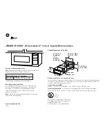
Room temperature .................. To = 21˚C

Initial temperature .................  T1 = 11

°

C

Temperature after (36 + 3) = 39 sec. ................................................................  T2 = 21

°

C

Temperature difference Cold-Warm ..............................................................  

T1 = 10

°

C

Measured output power
The equation is “P = 115 x 

T” ........................................... P = 115 x 10

°

C = 1150 Watts

TEST PROCEDURES

PROCEDURE

LETTER

COMPONENT TEST

JUDGEMENT: The measured output power should be at least 

±

 15 % of the rated output power.

CAUTION: 1

°

C CORRESPONDS TO 115 WATTS REPEAT MEASUREMENT IF THE POWER IS

INSUFFICIENT.

1000g

1000g

1000g

T1˚C

T2˚C

Heat up for 39 sec.

B

POWER TRANSFORMER TEST

WARNING: High voltages and large currents are present at the secondary winding and filament

winding of the power transformer. It is very dangerous to work near this part when
the oven is on. NEVER make any voltage measurements of the high-voltage
circuits, including the magnetron filament.

CARRY OUT 3D CHECKS.

Disconnect the leads to the primary winding of the power transformer. Disconnect the filament and
secondary winding connections from the rest of the HV circuitry. Using an ohmmeter, set on a low
range,  it is possible to check the continuity of all three windings. The following readings should be
obtained:

a. Primary winding .................... approx. 1.0 

b. Secondary winding ............... approx. 86 

c. Filament winding ................... less than 1

If the reading obtained are not stated as above, then the power transformer is probably faulty and
should be replaced.

CARRY OUT 4R CHECKS.

C

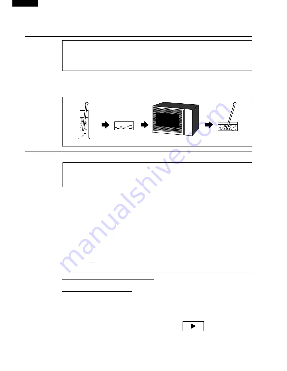
HIGH VOLTAGE RECTIFIER ASSEMBLY TEST

HIGH VOLTAGE RECTIFIER TEST
CARRY OUT 3D CHECKS.
Isolate the high voltage rectifier assembly from the HV circuit. The high voltage rectifier  can be tested
using an ohmmeter set to its highest range. Connect the ohmmeter across the terminal B+C of the
high voltage rectifier and note the reading obtained. Reverse the meter leads and note this second
reading. The normal resistance is infinite in one direction and more than 100 k

 in the other direction.

 CARRY OUT 4R CHECKS.

NOTE: FOR MEASUREMENT OF THE RESISTANCE OF THE RECTIFIER, THE BATTERIES OF

THE MEASURING INSTRUMENT MUST HAVE A VOLTAGE AT LEAST 6 VOLTS, BECAUSE
OTHERWISE AN INFINITE RESISTANCE MIGHT BE SHOWN IN BOTH DIRECTIONS.

B

C

HIGH VOLTAGE RECTIFIER

Summary of Contents for Carousel R-380E

Page 1: ...CE 4 FUNCTION OF IMPORTANT COMPONENTS 6 SERVICING 7 TEST PROCEDURE 9 TOUCH CONTROL PANEL 16 COMPONENT REPLACEMENT AND ADJUSTMENT PROCEDURE 21 MICROWAVE MEASUREMENT 27 WIRING DIAGRAM 28 PICTORIAL DIAGRAM 29 POWER UNIT CIRCUIT 30 CPU UNIT CIRCUIT 31 PRINTED WIRING BOARD 32 PARTS LIST 33 Info Display INST INSTANT ANT COOK COOK STOP STOP CLEAR CLEAR ST START ART TIMER CLOCK POWER LEVEL SLOW COOK SENSO...

Page 2: ...R 380E 40 ...

Page 3: ...d attached Never look into an open waveguide or antenna while the device is energized WARNING Never operate the oven until the following points are ensured A The door is tightly closed B The door brackets and hinges are not defective C The door packing is not damaged D The door is not deformed or warped E There is not any other visible damage with the oven Servicing and repair work must be carried...

Page 4: ...conds Microwave Power for Variable Cooking Repetition Rate HIGH Full power throughout the cooking time M HIGH approx 70 of Full Power MEDIUM approx 50 of Full Power M LOW approx 30 of Full Power LOW approx 10 of Full Power HELP PAD SENSOR INSTANT REHEAT PADS SENSOR COOK PADS EXPRESS DEFROST PAD EASY DEFROST PAD SLOW COOK PAD MORE LES PADS NUMBER PADS POWER LEVEL PAD CLOCK PAD TIMER PAD STOP CLEAR ...

Page 5: ... alter the cooking result for the automatic operations 6 EASY DEFROST PAD Presstodefrostfrozenfoodbyentering quantity 7 SLOW COOK PAD Press to cook slowly and for a longer time 8 QUICK AND EASY PAD Press to select Quick and Easy menus 9 NUMBER PADS Press to enter cooking times clock time weight or quantity of food 10 POWER LEVEL PAD Press to select microwave power setting If not pressed HIGH is au...

Page 6: ...ains on even if the oven door is opened after the cooking cycle has been interrupted because the relay RY1 stays closed Shown in the display is the remaining time 6 MONITOR SWITCH CIRCUIT The monitor switch is mechanically controlled by oven door and monitors the operation of the 1st latch switch and 2nd interlock relay 6 1 When the oven door is opened during or after the cycle of a cooking progra...

Page 7: ... is not turned on 3 After about 16 seconds the cook relay RY 2 is energized The power transformer is turned on microwaveenergyisproducedandfirststageisstarted The 16 seconds is the cooling time required to remove any vapor from the oven cavity and sensor NOTE During this first stage do not open the door or touch STOP CLEAR pad 4 When the sensor detects the vapor emitted from the food thedisplayswi...

Page 8: ...the oven cavity is designed to prevent damage to the oven by fire If the foods load is overcooked by either error in cook time or defect in the control unit the thermal cut out will open Under normal operation the oven thermal cut out remains closed However when abnormally high temperatures are reached within the oven cavity the oven thermal cut out will open at 125 C causing the oven to shut down...

Page 9: ...rry out 3D checks and reconnect the leads to the primary of the power trans former REMEMBER TO CHECK 4R 1 Reconnect all leads removed from components during testing 2 Replace the outer case cabinet 3 Reconnect the supply 4 Run the oven Check all functions Microwave ovens should not be run empty To test for the presence of microwave energy within a cavity place a cup of cold water on the oven turnt...

Page 10: ...oor opened Display ap pears Oven does not start when the START pad is touched Dis play appears Oven lamp does not light Dis play appears Fan motor does not operate Display appears Turntable motor assembly does not operate Display ap pears Oven or any electrical parts does not stop when cooking time is 0 or STOP CLEAR pad is touched Oven seems to be operating but little or no heat is produced in ov...

Page 11: ...d voltage Water load 1000 g Initial temperature T1 10 1 C Heating time 36 sec Mass of container mc 330 g T2 Final Temperature P 115 x T 0 55 x mc T2 T0 36 Measuring condition 1 Container The water container must be a cylindrical borosilicate glass vessel having a maximum material thickness of 3 mm and an outside diameter of approximately 190 mm 2 Temperature of the oven and vessel The oven and the...

Page 12: ...rom the rest of the HV circuitry Using an ohmmeter set on a low range it is possible to check the continuity of all three windings The following readings should be obtained a Primary winding approx 1 0 Ω b Secondary winding approx 86 Ω c Filament winding less than 1Ω If the reading obtained are not stated as above then the power transformer is probably faulty and should be replaced CARRY OUT 4R CH...

Page 13: ...minals as described in the following table Table Terminal Connection of Switch Plunger Operation COM to NO COM to NC COM Common terminal Released Open circuit Short circuit NO Normally open terminal Depressed Short circuit Open circuit NC Normally close terminal If incorrect readings are obtained make the necessary switch adjustment or replace the switch CARRY OUT 4R CHECKS CARRY OUT 3D CHECKS Dis...

Page 14: ...e switch s and the fuse M10A CARRY OUT 4R CHECKS CAUTION ONLY REPLACE FUSE M10A WITH THE CORRECT VALUE REPLACEMENT I BLOWN FUSE M10A J NOISE FILTER TEST CARRY OUT 3D CHECKS Disconnect the leads from the terminals of the noise filter Using an ohmmeter check between the termi nals as described in the following table MEASURING POINT INDICATION OF OHMMETER Between N and L Open circuit Between terminal...

Page 15: ...ement is described according to the symptoms indicated 1 Key Unit Note Check key unit ribbon connection before replacement The following symptoms indicate a defective key unit Replace the key unit a When touching the pads a certain pad produces no signal at all b When touching a number pad two figures or more are displayed c When touching the pads sometimes a pad produces no signal 2 Control Unit ...

Page 16: ...owave cooking operation DC voltage indicated Defective relay DC voltage not indicated Check diode which is connected to the relay coil If diode is good control unit is defective RELAY SYMBOL OPERATIONAL VOLTAGE CONNECTED COMPONENTS RY1 APPROX 25 0V D C Oven lamp Turntable motor Cooling fan motor RY2 APPROX 24 0V D C Power transformer CARRY OUT 4R CHECKS RY1 VRS1 T1 RY3 J1 a b c d P AH SENSOR TEST ...

Page 17: ...onnect the power supply cord after the outer case is installed 9 Reconnect the oven to the power supply and check the sensor cook operation as follows 9 1 Fill approximately 200 milliliters of tap water in a 1000 milliliter measuring cup 9 2 Place the container on the center of tray in the oven cavity 9 3 Close the door 9 4 Touch the CLOCK pad once the POWER LEVEL pad twice the START pad once the ...

Page 18: ...t A circuit to drive the magnetron fan motor turntable motor and light the oven lamp 5 Buzzer Circuit ThebuzzerisresponsivetosignalsfromtheLSItoemit audible sounds key touch sound and completion sound 6 Synchronizing Signal Circuit The power source synchronizing signal is available in order to compose a basic standard time in the clock circuit It accompanies a very small error because it works on ...

Page 19: ...microwave cooking and H level while not cooking In other cooking modes variable cooking the signal turns to H level and L level in repetition according to the power level ON and OFF times for other power level 31 P43 Terminal not used 32 CNTR0 OUT Signal to sound buzzer 2 0 kHz A key touch sound B Completion sound 33 P41 OUT Terminal not used 34 INT0 IN Signal synchronized with commercial power so...

Page 20: ...sensor This input is an analog input terminal from the AH sensor circuit and connected to the A D converter built into the LSI 51 RESET IN Auto clear terminal Signal is input to reset the LSI to the initial state when power is applied Temporarily set L level the moment power is applied at this time the LSI is reset Thereafter set at H level 52 NC Terminal not used 53 XCOUT OUT Terminal not used 54...

Page 21: ...s deviated to increase the voltage available at AIN5 terminal of the LSI Then the LSI observes that voltage at AIN5 terminal and compares it with its initial value and when the comparison rate reaches the preset value fixed for each menu to be cooked the LSI causes the unit to stop sensor cooking thereafter theunitgoesinthenextoperationautomatically When the LSI starts to detect the initial voltag...

Page 22: ...ls the power supply cord between the touch control panel and the oven proper is long enough that they may be separated from each other For those models therefore it is possible to check and repair the controls of the touch control panel while keeping it apart from the oven proper in this case you must short both ends of the door sensing switch on PWB of the touch control panel with a jumper which ...

Page 23: ...Magnetron Highvoltagetransformer and Oven cavity 3 Sharp edge Bottom plate Oven cavity Waveguide flange Chassis support and other metallic plate 4 Movable parts to prevent a fault Fan blade Fan motor Switch 3 Do not catch the wire leads in the outer case cabinet 4 Insert the positive lock connector certainly until its pin is locked And make sure that the wire leads should not come off even if the ...

Page 24: ...two 2 screws 2 Re install the magnetron to waveguide flange with the four 4 screws 3 Insertthetwo 2 tabsofthechassissupporttotheoven cavity front plate and back plate 4 Re install the chassis support to oven cavity front plate oven cavity rear plate magnetron and fan duct with the five 5 screws 5 Reconnect the wire leads to the magnetron Refer to PICTORIAL DIAGRAM 6 Re install outer case and check...

Page 25: ...r 3 Remove the magnetron and the chassis support from thewaveguide referringto MAGNETRONREMOVAL 4 Release the snap of the main wire harness from the fan duct 5 Remove one 1 screw holding the fan duct assembly to the oven cavity 6 Release the main wire harness from the hole of the fan duct 7 Release the fan duct from the waveguide flange 8 Release the fan duct assembly from the oven cavity 9 Remove...

Page 26: ...tight the screw 3 Connectthebrownandbluewireleadsofpowersupply cord to the noise filter correctly referring to the Pictorial Diagram 4 Hold the the wire leads of the main wire harness and the earth wire of the power supply cord with the one 1 purse lock 5 Re install outer case and check that the oven is operating properly 1ST LATCH SWITCH 2ND INTERLOCK RELAY CONTROL SWITCH AND MONITOR SWITCH REMOV...

Page 27: ...en button and open the door slightly 3 Insert a putty knife thickness of about 0 5mm into the gapbetweenthechokecoveranddoorframeasshown in Figure C 6 to free engaging parts 4 Pry the choke cover by inserting a putty knife as shown Figure C 6 5 Release choke cover from door panel 6 Now choke cover is free 7 Release two 2 pins of door panel from two 2 holes of upper and lower oven hinges by lifting...

Page 28: ...e leakage of microwave energy from oven cavity during cook cycle This function does not require that door be air tight moisture condensation tight or light tight Therefore occasional appearance of moisture light or sensing of gentle warm air movement around oven door is not abnormal and do not of themselves indicate a leakage of microwave energy from oven cavity Sealer film Backing film Adhesive t...

Page 29: ...formicrowaveovensmustbeusedfortesting Recommended instruments are NARDA 8100 NARDA 8200 HOLADAY HI 1500 SIMPSON 380M 2 Place the oven tray into the oven cavity 3 Place the load of 275 15ml of water initially at 20 5 C in the centre of the oven tray The water container should be a low form of 600 ml beaker with inside diameter of approx 8 5cm and made of an electrically non conductive material such...

Page 30: ...M10A N L LINE CROSS CAPACITOR 0 068µ AC250V NOISE SUPPRESSION COIL LINE BYPASS CAPACITOR 0 0022µ AC250V LINE BYPASS CAPACITOR 0 0022µ AC250V NOISE FILTER 230 240V 50Hz CAPACITOR 1 13µ AC2300V 2ND INTERLOCK RELAYCONTROL SWITCH CONTROL UNIT F1 F2 F3 AH SENSOR POWER TRANSFORMER MAGNETRON H V RECTIFIER H V FUSE 0 75A CAPACITOR 1 13µ AC2300V TURNTABLE MOTOR FAN MOTOR OVEN LAMP 2ND INTERLOCK RELAYCONTRO...

Page 31: ... THERMAL CUT OUT OVEN BLK BLK RED GRY WHT BLK BLU BRN POWER SUPPLY CORD EARTH NEUTRAL LIVE G Y N L WHT RED NOTE Neutral WHT wire must be connected to the terminal with black mark on the oven light socket COM MONITOR SWITCH COM N O N C 2ND INTERLOCK RELAY CONTROL SWITCH 1ST LATCH SWITCH COM NO RED ORG YLW BLK YLW RED GRN GRN GRY WHT GRY WHT 2 1 GRY WHT YLW BLK RY2 RY1 SP1 IC1 SECONDARY INTERLOCK RE...

Page 32: ...C4 10µ 35v R1 2 4k 1SS270A 1SS270A D1 D4 11ES1 D6 R5 4 7k R2 680 1 2w R3 510 1 2w R6 3 3k Q2 2SB1238 SP1 PKM22EPT Q1 2SB1238 RY1 RY2 Q3 KRC243M CN C 12PIN LEAD WIRE HARNESS LED GND VC VA INT VR BUZZER MICRO NC NC OVEN LAMP TURNTABLE MOTOR FAN MOTOR AC AC MICRO 2ND INTERLOCK RELAY CONTROL SWITCH 2ND INTERLOCK RELAY CONTROL SWITCH OVEN LAMP TURNTABLE MOTOR FAN MOTOR C10 C 2 C 3 C 1 C 4 C 9 C 5 C 6 C...

Page 33: ...144 36 1 COM4 COM3 COM2 COM1 COM0 VL1 VL2 VL3 VL4 VL5 C3 C2 C1 VLIN VREG NC VSS P27 P26 P25 P24 P23 P22 P21 P20 P47 P46 P45 P44 P43 CNTR0 P05 COM6 COM16 COM15 COM14 COM13 COM12 COM11 COM10 COM9 SEG40 SEG39 SEG38 SEG37 SEG36 SEG35 SEG34 SEG33 SEG32 SEG31 SEG30 SEG29 SEG28 SEG27 SEG26 SEG25 SEG24 SEG23 SEG22 SEG21 SEG20 SEG19 SEG18 SEG17 SEG16 SEG15 SEG14 SEG13 SEG12 SEG11 SEG10 SEG9 SEG8 SEG7 SEG6 ...

Page 34: ... B C D E F G H A B C D E F G H 2 3 4 5 6 1 2 3 4 5 6 1 DIP F SW R3 SP1 R2 E B R1 C4 C2 C5 RY2 RY1 VRS1 P S T1 RY3 D6 D1 D4 D8 D2 D3 D20 D5 R4 Q2 Q3 B B E E R6 D9 D7 J2 J1 D10 R5 R9 ZD1 1 2 C3 C1 CN C CN A CN B CN D SH B SH A RED GREEN 1 1 1 2 2 12 ...

Page 35: ...in connector CN B 1 AB 3 1C FW VZA232DRE0 12 pin harness CN C 1 AE C1 RC KZA087DRE0 Capacitor 0 1µF 50V 1 AA C2 VCEAB31VW108M Capacitor 1000µF 35V 1 AF C3 RC KZA087DRE0 Capacitor 0 1µF 50V 1 AA C4 5 VCEAB31VW106M Capacitor 10µF 35V 2 AA D1 4 VHD11ES1 1 Diode 11ES1 4 AB D5 8 VHD1SS270A 1 Diode 1SS270ATA 4 AA Q1 2 VS2SB1238 3 Transistor 2SB1238 2 AA Q3 VSKRC243M 3 Transistor KRC243M 1 AB R1 VRD B12E...

Page 36: ...82WRE0 Sealer film 1 AH 5 3 GWAKPA816WRRZ Door frame 1 AW 5 4 HPNL A745WRRZ Door screen 1 AR 5 5 LSTPPA193WRFZ Latch head 1 AE 5 6 MSPRTA187WRE0 Latch spring 1 AC 5 7 XEPSD40P08000 Screw 4mm x 8mm 6 AA 5 8 PCUSUA461WRP0 Cushion 1 AB 5 9 PCUSUA553WRPZ Cushion 1 AC 5 10 PCUSUA554WRPZ Cushion 1 AB 5 11 GCOVHA417WRFZ Choke cover 1 AG MISCELLANEOUS 6 1 FROLPA079WRK0 Turntable support 1 AQ 6 2 NTNT A079...

Page 37: ... 2 4 22 6 4 7 6 1 12 7 1 7 5 1 7 1 8 4 10 4 16 1 6 7 1 2 3 2 3 7 5 7 5 7 6 7 6 1 9 4 6 1 3 1 2 1 17 1 15 7 7 7 6 4 23 4 9 1 16 7 2 1 13 7 3 4 8 4 4 4 15 4 18 7 6 7 6 1 4 4 7 4 11 7 3 7 6 4 25 7 4 4 25 4 24 7 8 7 6 4 19 4 12 6 10 6 2 6 1 4 1 7 6 2 4 4 20 7 3 1 5 7 1 4 5 2 2 7 1 4 3 7 3 1 1 1 1 7 1 1 14 7 3 7 3 7 6 1 18 1 5 6 6 4 17 7 1 4 21 4 26 ...

Page 38: ...H 2 3 4 5 6 1 2 3 4 5 6 CONTROL PANEL PARTS MISCELLANEOUS DOOR PARTS 3 2 3 1 3 5 3 4 3 6 3 3 1 3 6 3 3 6 7 Actual wire harness may be different from illustration 6 3 6 5 6 9 5 11 5 1 5 3 5 4 5 7 5 7 5 7 5 6 5 7 5 2 5 5 5 10 5 10 5 9 5 9 5 8 6 4 ...

Page 39: ...WRE0 TOP PAD ASSEMBLY FPADBA428WRKZ PLASTIC BAG SSAKHA034WREZ Not replaceable items PACKING CASE SPAKCD624WREZ BOTTOM PAD ASSEMBLY FPADBA429WRKZ 6 2 TURNTABLE TRAY 6 8 INSTRUCTION BOOK PRINTING MATTER 6 1 TURNTABLE SUPPORT TRAY PACK SPADFA451WRE0 INTO THE OVEN CAVITY ...

Page 40: ...R 380E 38 2001SHARP CORP 7K0 300E Printed in Australia ...

Reviews: