


AR-NB3
TROUBLE CODE
6 – 1
[ 6 ] TROUBLE CODE
1. TROUBLE CODE (CE CODE)
If a transmission error occurs when you send a scanned image, a mes-
sage informing you of the error and an error code will appear in the dis-
play on the machine.
2. KEY OPERATOR PROGRAMS
The key operator programs allow the administrator of the machine (key
operator) to enable and disable functionsó to suit the needs of the work-
place. This chapter explains the key operator programs for the network
scanner functions.
Note: For the initial key operator code set at the factory, see "PRO-
GRAMMING THE KEY OPERATOR CODE" in the "Key opera-
tor's guide".
2-1. KEY OPERATOR PROGRAM LIST
The key operator programs for the network and printer functions are
shown in the following table.
Factory default settings are indicated in bold.
2-2. USING THE KEY OPERATOR PROGRAMS
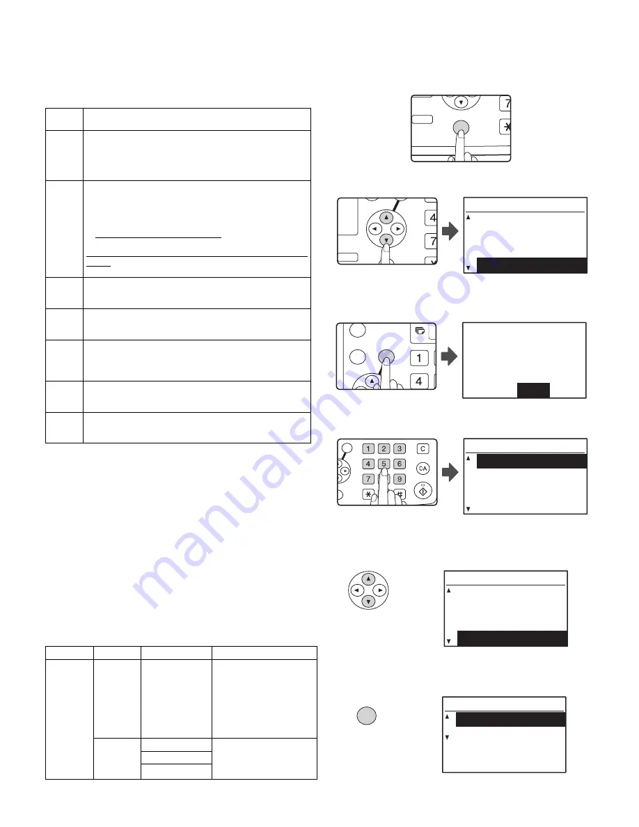
1. Press the [SPECIAL FUNCTION] key.
The special function screen will appear.
2. Select "KEY OPERATOR PRG." with the [
b
] or [
c
] key.
3. Press the [OK] key.
The key operator code entry screen appears.
4. Enter the key operator code with the numeric keys.
• "
*
" will appear for each digit will enter.
• The mode selection screen will appear.
5. Select the desired mode with the [
b
] or [
c
] key.
6. Press the [OK] key.
The settings of the selected mode will appear.
Example: The screen when "SCANNER" is selected.
Error
Code
Solution
CE-00
CE-01
Turn off the power and then turn it back on. Consult with
your network administrator to make sure that no problems
exist on the network or in the server. If the error is not
cleared after turning the power off and on, turn off the power
and contact your dealer.
CE-02
CE-04
The scanned image was not sent because a connection to
the server could not be established. Make sure that the
SMTP server settings or Scan to FTP destination settings in
the Web page are correct.
The procedure for configuring the SMTP server is explained
in "VARIOUS SERVER SETTINGS", and the procedure for
editing Scan to FTP destination information is explained in
"Editing and deleting programmed transmission destina-
tions". For information on the settings to be entered, see
Help in the Web page.
CE-03
The scanned image was not sent because the server was
busy or there was too much traffic on line. Wait briefly and
then try again.
CE-05
The scanned image was not sent because the directory of the
destination FTP server was not correct. Make sure that the cor-
rect FTP server information is configured in the Web page.
CE-09
The size of the scanned image file exceeds the limit set in
"Maximum Size of E-mail attachments" in the Web page.
Reduce the number of original pages scanned into the file, or
change the limit set in "Maximum Size of E-mail attachments".
CE-11
The memory became full during scanning. Scan less pages,
lower the resolution, or change the color mode so that the
file size is smaller, and try scanning again.
CE-12
The maximum number of destinations of a global address
search has been exceeded. Increase the number of search
characters to narrow the range of the global address search.
Mode
Program
Settings
Explanation
SCANNER DISABLE
U S B
SCAN
YES, NO
S e l e c t w h e t h e r o r n o t
scanning from a computer
a n d s c a n n i n g f ro m t h e
m a c h i n e a r e d i s a b l e d
when a USB connection is
used.
When "YES" is selected,
USB scanning is disabled.
INITIAL
COND.
COLOR MODE
This is used to change the
de fa u lt sett in gs for t he
color mode, format, and
resolution.
FORMAT
RESOLUTION
2-SIDED
COPY
SPECIAL FUNCTION
ACC.
DUPLEX SCAN
GH
PQR
2-SIDED
COPY
SPECIAL FUNCTION
SPECIAL FUNCTION
PAPER SIZE SET
DISPLAY CONTRAST
TOTAL COUNT
KEY OPERATOR PRG.
GHI
OK
BACK
Enter key operator
code.
KEY OPERATOR CODE:
-----
ABC
DEF
JKL
GHI
MNO
TUV
PQRS
WXYZ
@.-_
FUNCTION
ACC. #-C
READ-END
OK
MODE SELECT
KEY OP. # CHANGE
COPIER
PRINTER
SCANNER
MODE SELECT
KEY OP. # CHANGE
COPIER
PRINTER
SCANNER
OK
SCANNER
DISABLE USB SCAN
INITIAL COND.
Summary of Contents for AR-NB3
Page 2: ......
Page 10: ......
Page 33: ...AR NB3 PARTS LAYOUT 8 1 8 PARTS LAYOUT 1 PARTS SIDE ...
Page 34: ...AR NB3 PARTS LAYOUT 8 2 2 SOLDER SIDE ...
Page 36: ......