Sharp Aquos LC-52SE94U Service Manual Download Page 80

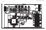
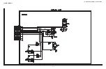
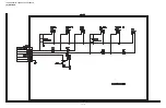
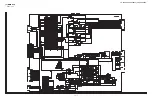
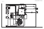
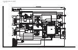
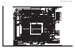
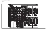
LC-52SE94U/LC-52SE941U/LC-65SE94U

9 – 9

A

C

B

D

E

F

G

I

H

1

2

3

4

5

6

7

8

9

10

11

12

13

14

15

16

17

18

19

20

21

22

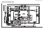
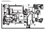
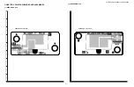
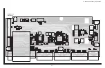
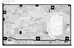
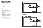
MAIN Unit (Side-B Chip)

TL2328

R1301

R1335

IC1301

R1324

Q1305

R1308

D1304

C1303

R1341

R1314

TL9502

TL9503

C1301

R1306

Q1307

C1308

R1315

IC1302

R1307

Q1301

R1305

TL9501

R1303

R9515

R9533

C9508

C9510

C9516

R9517

FB9501

C9524

R9510

R9512

C9507

R9511

R9516

C3211

R3235

L2202

C3216

C3214

C3212

C3232

R3224

TL2259

TL2232

C3224

L3202

TL2230

TL2297

R3209

R3212

R2244

C3231

R3208

IC3201

R2243

C2224

C3222

C3221

Q2210

C3218

R2253

R2256

C3217

TL2290

R2249

R2245

C2225

R3233

R3237

R3236

C3230

R2246

Q2211

C3204

R3207

TL2264

R3234

R2254

R2257

R2250

TL2291

TL2263

R2248

R2247

C2226

Q2212

TL2292

R2255

R2258

TL2294

TL2262

TL2295

R2251

TL2260

TL2261

R2305

TP2205

TL1621

R2304

TL2258

D2210

TL2296

TL2293

D2211

R2338

R2343

R2342

R2341

TL1620

TL2231

R1608

R1680

R1682

R1604

D1601

R1667

R1674

R1675

R1686

C1653

R1688

R1670

R1672

R1610

C1632

C1633

IC1606

C1642

C1636

C1673

C1626

C1627

C1637

R1678

R1687

R1685

C1674

C1629

C1681

TL1622

C1647

C1648

C1628

C1675

R1684

R1662

R1666

FB1607

TL1602

IC1607

C1625

C1624

C1630

R1683

C1652

C1643

C1680

C1644

R1729

C1635

C1645

C1639

C1623

FB1606

C1620

C1634

C1646

C1638

C1622

C1619

C1621

C1631

C1640

TL1601

C1641

D1619

D1614

C1617

R1722

R1673

R1671

R1665

R1663

C1618

R1669

R1668

Q1609

R1623

TL1614

TL1613

R1641

R1640

R1624

TL1618

R1637

TL1615

IC1603

C1612

FB1605

R1609

C1611

R1724

Q1606

Q1603

D1607

Q1618

R1616

D1604

IC1601

D1611

C1607

C1609

D1613

TL1611

R1602

TL1616

R1630

R1627

C1613

FB1603

TL1603

D1605

R1629

C1615

TL1609

R1607

D1603

TL1619

C8082

R1612

Q1607

Q1605

Q1602

TL1606

R1620

FB8003

R1723

C8014

TL9201

TL1607

TL9241

TL9206

IC8002

TL9240

TL9239

TL9203

TL1604

TL9224

TL9223

R9204

R9212

R9202

R9207

R9208

TL9205

TL9204

TL9222

R9012

TL9221

TL9208

R9211

TL9202

TL9207

LUG2206

TL9275

TL1303

TL1304

C9006

TL1302

C8221

C8220

R8203

R8204

R8205

TL9010

C8156

C8161

C8160

TL9007

TL9006

C8162

C8163

TL9004

TL9008

C8158

C8170

C8169

R8226

R8225

TL9009

C8218

C8219

BAR4

TL9238

C8217

TL9237

TL9236

R2615

LF2

TL2639

TL2623

FB2606

FB2608

TL2657

TL2642

FB2607

FB2605

TL9235

FB2604

TL2628

TL2603

TL2625

TL2626

TL2627

TL2643

TL2624

FDC2

TL2659

TL9234

R8613

R8614

TL2638

C8609

TL2660

TP8626

TL2677

TL2664

TL2661

TL2658

TL2662

TL2647

R8612

LUG2208

TL2644

TL2656

TL2646

R8027

TL2641

C8608

TL2655

TL2645

R8036

TL2651

R8028

TL2640

TL2602

R2622

C8611

R8033

R8611

IC8155

C8192

TP8625

TP8622

C8606

R8616

C8610

TL8151

C8193

TL9605

C8195

C8194

TL8152

R8270

R8271

C8207

C8208

C8209

C8210

C8211

C8212

C8213

C8214

C8215

C8216

R8240

R8243

R8241

R8244

R8242

R8227

R8224

R8223

C8188

C8187

C8167

C8168

C8185

C8184

C8177

C8157

C8183

C8182

C8181

C8179

C8180

C8159

R8206

R8207

R8208

R8209

R8210

R8211

R8212

R8213

C8226

C8227

C8222

C8224

C8225

C8223

R8181

R8170

R8164

R8165

R8202

R8171

R8173

R8200

R8198

R8176

R8178

R8179

R8169

R8180

R8172

R8174

R8201

R8199

R8175

R8177

R8251

R8167

R8034

R8166

R8168

R8163

C8029

C8031

C8041

C8055

R8267

C8001

C8002

R8120

R9018

R8116

C8087

C8016

R8122

R8114

C8012

R8093

C8028

R8129

C8024

R8138

C8046

C8030

R8001

R8031

C8033

C8035

C8045

C8037

C8039

C8047

C8049

C8053

R8059

C8044

C8068

C8051

C8009

C8088

C8050

C8026

C8032

C8019

TL8029

R8097

R8096

R8018

C8034

C8010

C8013

C8015

C8017

R8065

C8057

C8067

R8903

C8023

C8086

R9315

R9310

R9313

C8063

C8020

FB8002

C8008

C8076

C8018

C8062

C8007

C8006

C8060

C8036

R8136

C8005

C8059

R8137

C8004

C8058

C8021

C8022

R8013

R9324

C8065

C8038

R8905

R8014

C8040

R8140

C8011

TP8046

C8090

C8048

C8052

R8017

C8042

TP9303

C8066

C8061

C8056

C8054

C8075

R8100

C8070

C8025

C8079

C8027

C8003

C8073

TP9302

C8096

C8043

TP8050

C8084

C8906

C8910

C8908

C8904

C8902

C8106

R8145

C8109

C8099

R8131

R8039

C8074

C8114

C8104

C8098

C8101

C8103

C8092

C8105

R8038

TP8055

C8102

C8915

C8149

C8064

C8072

TP8052

C8095

R8144

C8080

C8077

R8142

C8916

C8913

C8912

C8911

C8914

C8071

C8069

C8116

C8112

C8097

C8903

C8901

C8094

C8905

C8907

C8115

C8100

C8078

R8090

C8083

C8909

C8081

TL8005

R8026

R8141

R8084

TL8006

FB8011

FB8010

FB8009

FB8008

FB8007

TP8074

R8021

TL2336

TL2331

TL2334

TL2330

TL2333

TL2332

TL2335

TL1801

R1832

R1828

C1831

R1805

BAR2

IC1804

R1827

R1804

C1830

R1823

FL1801

R1830

R1815

R1826

R1814

R1811

C1826

C1825

C1816

C1821

R1803

C1818

R1802

C1823

C1827

C1817

C1815

C1819

C1813

C1822

C1824

C1809

C1820

C1808

C1807

C1814

TL8007

C1835

TL8008

TL3304

IC3302

R3334

R3335

C3327

R3341

C3304

C3303

C3338

Q3301

R2352

TL3301

FB3302

C3330

C3333

R3314

R2336

C3311

C3339

C3329

C3210

C3305

C3205

C3331

R2344

R2334

C3206

R3353

C3332

R3340

R2339

C3203

C2251

R2335

R2345

R2340

C3207

C3228

C3229

R2271

R2268

C3201

TP2201

R2236

C3209

C3208

C9520

R9524

Q2214

C2242

C1430

R1432

R2315

C9521

R2265

R1456

R1454

R1462

R2264

C9522

C1465

C1461

R1458

R1460

IC1407

C1464

R9525

C1460

R1457

R1459

R1455

R1453

R1461

C9523

R1431

C1429

C1462

R9520

R9523

C1426

C1428

R9519

R9518

R1426

R1425

C1427

C1425

C1423

R2323

R1401

R1402

R1406

R1405

C1424

C1422

Q1309

D1305

C1441

R1338

IC1401

IC1405

C1440

IC1403

R1422

D1302

C1415

C1421

C1446

D1311

C1444

R1337

R1404

R1450

C1403

C1408

C1414

TL2210

D1313

C1409

C1314

C1402

R1414

TL2211

C2028

R1323

TL2321

TL2325

C2029

C1406

R1415

C1407

C2027

TL2327

TL2326

TL2324

R1411

R1410

R1409

R1408

TL2003

FB2001

TL2337

TL2002

TL2005

TL2317

TL2004

TL2322

TL2323

TL2320

TL2329

TL2318

TL2319

TL2213

TL2215

TL2202

TL2214

TL2216

TL2218

TL2220

TL2203

TL2217

TL2219

TL2222

TL2212

FDC4

TL2221

TL2201

Q2204

C1443

R1447

C1454

TL2300

TL2302

R1439

R1438

TL2283

C1445

C1451

R2324

TP2206

R2320

R2313

R2314

TL2289

R1437

IC1406

Q2218

C1442

TL2255

R2319

TL2256

TL9720

C1450

TL2286

TL2254

R1446

R2322

TL2316

C1448

R1442

TL2250

TL2252

C2249

R2321

R1441

TL2285

C1455

TL2243

C1447

R2317

Q2217

C1453

R1444

R2318

TL2282

TL2281

C2248

TL2280

R2351

R2348

TL2279

TL2248

R2350

R2347

TL2278

R2349

R2346

TL2277

TL2238

TL2274

TL2251

TL2246

TL2244

TL2299

TL2314

TL2298

TL2272

TL2239

TL2240

TL2271

TL8456

TL2270

R2329

TL2237

C8451

R1330

R1318

TL2269

R2325

R9010

TL2242

Q2219

TL2276

C8453

R2326

IC8451

R2331

TL2268

TL2275

R8456

Q1306

C8452

C2250

TL2234

TL2267

R8457

R2332

TL2266

TL2233

R1329

R1317

TL2265

R9011

C8460

TL8454

TL2229

TL2312

Q2220

C8462

TL2227

TL2310

IC8454

TL8455

TL2226

R2328

R8474

TL2309

C8461

R2327

R8475

TL2225

R2330

TL2308

TL2223

TL2306

TL2236

TL2006

R8452

R8451

TL2209

TL2304

TL2007

TL2208

Q2007

TL2008

Q2001

C8454

TL2009

TL2010

IC8453

R2003

R2076

C8457

TL2011

Q2006

TL2012

C8455

TL8453

TL2014

R2007

TL2013

C2002

C2003

C2001

IC2001

TL2001

R2025

TP2003

TP2015

R2006

TL9213

R2070

R2001

TP2012

TP2014

TP2017

TP2019

C2008

C2015

R2051

R2052

C2014

TL9212

R2050

R2071

TP2013

TP2011

R2023

R2024

R2019

TP2002

TP2006

TP2004

TP2005

IC2002

R2005

R2013

R2002

R9201

R2075

R2072

C2012

R2042

TL9210

R2012

TP2029

R2017

R2077

C2013

R2026

C2010

R2018

R2029

R2058

R2034

R2036

TP2010

R2044

R2048

TP2020

R2027

X2002

TL2015

TP2018

TP2023

TL9209

TL9211

R2028

TP2007

TP2009

TL9219

TL9220

R9009

R2016

TL9722

TL9353

TL9352

TL9335

TL9336

TL9337

TL9338

TL9380

TL9334

TL9339

TL9345

TL9340

TL9344

TL9341

TL9333

TL9342

TL9332

TL9379

TL9343

TL9330

TL9329

TL9347

TL9346

TL9327

TL9331

TL9328

TL9348

TL9349

TL9326

TL9381

TL9350

TL9357

TL9351

TL9354

R9303

TL9355

R9304

TL9316

TL9383

TL9317

TL9315

TL9313

TL9314

TL9302

TL9312

TL9311

TL9359

TL9322

TL9382

R9325

TL9320

TL9324

TL9378

TL9301

TL9375

TL9318

TL9325

TP9301

R9318

R9316

TL9310

TL9319

TL9321

TL9323

Q9701

R8016

TL8457

Q9301

D9703

R9314

D9713

TL9384

R8007

R8010

D9701

TL9724

C9711

Q9702

R9736

C9709

TL9708

R9705

R9704

D9702

TL9717

R8009

D9609

TL9733TL9716TL9702 TL9715 TL9710 TL9711

TL9701

LUG2207

R8055

C8228

C8229

D9602

TL9603

TL9723

R8214

R9610

R9611

R9625

D9601

C9604

IC9602

R9612

C9629

C8178

C9607

TL9602

C9624

R9644

R9643

R9642

R9641

C8176

D9641

C9644

IC9641

C9643

C9641

R9601

C9606

TL9604

C9642

R9605

R9606

R9603

C8206

R9604

C9601

C9605

R9608

R9607

C9602

C8205

C9610

D9605

R9602

R9613

IC9601

D9603

R9629

D9607

C9611

C9609

R9619

R9617

R9616

R9614

R9618

R9609

D9606

C9615

IC9605

C9614

C9608

TL2669

C9612

R9034

C2607

R2638

C9005

R9035

R2637

C2608

R2619

TL2622

TL2674

IC2602

R2605

IC2601

R2631

R2620

TL2675

C2609

TL2649

TL2635

TL2610

TL2621

TL2601

TL2605

TL2609

TL2672

C2602

FB2609

TL2648

TL2650

TL2652

TL2618

TL2667

FB2603

D2601

FB2602

Summary of Contents for Aquos LC-52SE94U

Page 1: ...CHAPTER 6 TROUBLE SHOOTING TABLE 1 TROUBLE SHOOTING TABLE 6 1 CHAPTER 7 MAJOR IC INFORMATIONS 1 MAJOR IC INFORMATIONS 7 1 CHAPTER 8 OVERALL WIRING BLOCK DIAGRAM 1 OVERALL WIRING DIAGRAM LC 52SE94U LC 52SE941U 8 1 2 OVERALL WIRING DIAGRAM LC 65SE94U 8 2 3 SYSTEM BLOCK DIAGRAM LC 52SE94U LC 52SE941U 8 3 4 SYSTEM BLOCK DIAGRAM LC 65SE94U 8 4 CHAPTER 9 PRINTED WIRING BOARD ASSEMBLIES 1 SPEAKER L Unit ...

Page 2: ...LC 52SE94U LC 52SE941U LC 65SE94U i LC 52SE94U LC 52SE941U LC 65SE94U Service Manual OUTLINE OUTLINE The stand ST52SE94 and speakers SP52SE94 for Model LC 52SE941U are separately sold ...

Page 3: ...cross the resistor All checks must be repeated with the AC cord plug connection reversed If necessary a nonpolarized adaptor plug must be used only for the purpose of completing these checks Any reading of 0 75 Vrms this corresponds to 0 5 mA rms AC or more is excessive and indicates a potential shock hazard which must be corrected before returning the monitor to the owner SAFETY NOTICE Many elect...

Page 4: ...de résistancecapacité les isolateurs mécaniques etc S assurer qu il n y ait pas de danger d électrocution en vérifiant la fuite de courant de la facon suivante Brancher le cordon d alimentation directem ent à une prise de cou rant de 110 240V Ne pas utiliser de transformateur d isolation pour cet essai A l aide de deux fils à pinces brancher une résistance de 1 5 kΩ 10 watts en parallèle avec un c...

Page 5: ...tional lead solder by 40 C and as it has poor solder wettability you may be apt to keep the soldering bit in contact with the PWB for extended period of time However Since the land may be peeled off or the maximum heat resistance temperature of parts may be exceeded remove the bit from the PWB as soon as you confirm the steady soldering condition Lead free solder contains more tin and the end of t...

Page 6: ...mation pro tection management measures 1 When disposing of the component parts and PWBs destruct the IC itself in a proper way For repairing or replacing the component parts and PWBs as well as clearing those in stock 2 In storing the component parts protect and manage them against theft and disclosure For storing the service parts service units etc Applied part HDCP KEY ROM IC8451 RH IXC318WJQZY ...

Page 7: ... only Operating temperature 32 F to 104 F 0 C to 40 C 1 Emergency alert messages via Cable are unreceivable 2 The dimensional drawings are shown on the inside back cover As part of policy of continuous improvement SHARP reserves the right to make design and specification changes for product improvement without prior notice The performance specification figures indicated are nominal values of produ...

Page 8: ... 135ch non scrambled channel only Digital Terrestrial Broadcast 8VSB 2 69ch Digital cable 1 64 256 QAM 1 135ch non scrambled channel only Audio multiplex BTSC System Audio out 15W 2 Terminals Rear INPUT 1 AV in COMPONENT in INPUT 2 AV in S VIDEO in INPUT 5 HDMI in with HDCP INPUT 6 Audio in HDMI in with HDCP INPUT 7 15 pin mini D sub female connector Audio in Ø 3 5 mm jack ANT CABLE 75 Unbalance F...

Page 9: ...ide INPUT 3 terminals RS 232C terminal DIGITAL AUDIO OUTPUT terminal INPUT 6 terminals HDMI INPUT 7 terminals PC IN ETHERNET terminal INPUT 5 terminal HDMI Antenna Cable in INPUT 1 terminals AC INPUT terminal INPUT 2 terminals AUDIO OUTPUT terminals POWER button MENU button INPUT button Channel buttons CH Volume buttons VOL INPUT 4 terminal HDMI SERVICE terminal Hold down the set s POWER button fo...

Page 10: ...on Indicator lights up for the current mode To enter the code registration mode you need to press FUNCTION and DISPLAY at the same time 18 LIGHT When this button is pressed some buttons for example VOL and CH on the remote control unit will light The lighting will turn off if no operations are performed within about 5 seconds This button is used for performing operations in low light situations 19...

Page 11: ...cushioning over the base area to lay the TV on This will prevent it from being damaged Unfasten the four screws used to secure the stand in place Detach the stand from the TV Appendix To attach the stand perform the above steps in reverse order 1 2 LC 65SE94U Before attaching detaching the stand Before performing work make sure to turn off the TV 3 Attach the stand hole covers Align the tabs of th...

Page 12: ...s picture size made correctly Adjust the picture tone Is the room too bright The picture may look dark in a room that is too bright Check the input signal setting Is the sleep timer set Check the power control settings The unit s internal temperature has increased Remove any objects blocking vent or clean Is connection to other components correct Is correct input signal source selected after conne...

Page 13: ...etup Interactive Service Software Update Identification On Screen Display Menu For TV INPUT 1 2 3 Mode For HDMI PC IN Mode For HTML Mode Picture Menu OPC Backlight Contrast Brightness Color Tint Sharpness Advanced C M S Hue C M S Saturation Color Temp Active Contrast Fine Motion Advanced I P Setting Film Mode Digital Noise Reduction Range of OPC Reset Audio Menu Treble Bass Balance Surround Bass E...

Page 14: ... i t i n U m m h c n i t i n U 15 3 4 400 13 1 2 343 18 25 32 477 48 29 32 1242 3 1 2 89 5 3 64 128 45 9 16 1157 1 3 5 6 1 5 9 7 9 2 1 4 3 4 7 3 3 5 2 4 6 8 4 8 2 3 2 3 3 5 5 2 1 2 2 3 6 1 5 6 8 1 7 8 9 7 4 5 1 3 4 0 0 4 5 5 2 4 6 7 3 1 LC 52SE94U 15 3 4 400 48 29 32 1242 3 1 2 89 45 9 16 1157 29 1 4 743 25 21 32 651 6 15 3 4 400 5 25 64 137 LC 52SE941U ...

Page 15: ...E94U m m h c n i t i n U 7 1 1 2 4 6 0 4 4 25 19 32 650 12 13 16 325 0 6 5 2 4 6 4 3 5 1 6 5 9 2 4 6 5 3 3 4 1 31 3 4 806 5 40 3 32 1018 37 49 64 959 35 3 4 908 22 9 32 566 1 3 3 6 1 2 9 7 6 1 7 4 6 9 0 4 5 3 6 4 6 2 5 1 2 21 64 59 3 1 6 4 6 0 0 1 LC 65SE94U ...

Page 16: ... screws and detach the Speaker Box Unit 3 Remove the 4 hole covers 4 Remove the 7 lock screws 5 Remove the 3 lock screws 6 Remove the 1 black sheet 1 lock flat head screw 7 Remove the 4 black sheets 4 lock screws and detach the Rear Cabinet CAUTION In the case of assembly the new sheet PSPAKA237WJ00 and PSPAGA386WJ00 can be stuck on these screws 4 5 2 6 6 7 3 Rear Cabinet Speaker Box Unit Front Ca...

Page 17: ...65SE94U 4 2 8 Remove the 8 lock screws and detach the Main Shield 9 Remove the 6 lock screws and detach the AV Shield 10 Remove the 4 lock screws and detach the Control PWB Shield Main Shield AV Shield 8 9 Control PWB Shield 10 ...

Page 18: ...2SE94U LC 52SE941U LC 65SE94U 4 3 11 Disconnect all the connectors from all the PWBs 11 11 11 11 LW LW US RA RA HM KM LP LB LC LB LA2 SP R VD PE MA PE SP PD PD LA2 LA1 AC AC LC LA1 PL LP PL SP L VD HM US KM ...

Page 19: ...LC 52SE94U LC 52SE941U LC 65SE94U 4 4 12 Remove the 2 lock screws and detach the Terminal Angle Bottom 13 Remove the 5 lock screws and detach the Tray Chassis Terminal Angle Bottom Tray Chassis 13 12 ...

Page 20: ...6 Remove the 6 lock screws and detach the POWER Unit 17 Remove the 5 lock screws and detach the TERMINAL Unit 18 Remove the 1 lock rivet and detach the Main Shield Plate 19 Remove the 3 lock screws 2 lock screws and detach the Heat Sink and MAIN Unit MAIN Unit Main Shield Plate TERMINAL Unit POWER Unit AC INLET Unit 19 19 18 16 17 15 Heat Sink Main Terminal Angle 14 14 14 ...

Page 21: ...Cover from the Mini AV KEY Angle 24 Remove the 1 lock screw and detach the Operation Button KEY Unit from the Mini AV KEY Cover 25 Remove the R C LED Unit 26 Remove the 14 lock screws and detach the Panel Support Angle Stand Assist Cover 27 Remove the 8 lock screws and detach the LCD Panel Module 26 26 26 20 25 22 23 24 23 20 21 21 Stand Assist Cover Panel Support Angle Panel Support Angle Speaker...

Page 22: ... the 4 hole covers 4 Remove the 2 lock screws 5 Remove the 3 lock screws 6 Remove the 1 black sheet 1 lock flat head screw 7 Remove the 5 black sheets 14 lock screws and detach the Rear Cabinet CAUTION In the case of assembly the new sheet PSPAKA237WJ00 and PSPAGA386WJ00 can be stuck on these screws Front Cabinet Speaker Box Unit Stand Rear Cabinet Black Sheet 7 5 6 2 1 7 4 Black Sheet 6 3 ...

Page 23: ...65SE94U 4 8 8 Remove the 8 lock screws and detach the Main Shield 9 Remove the 6 lock screws and detach the AV Shield 10 Remove the 4 lock screws and detach the Control PWB Shield AV Shield Main Shield Control PWB Shield 8 10 9 ...

Page 24: ...ch the Mini AV Shield SIDE Unit Mini AV KEY Cover from the Mini AV KEY Angle 14 Remove the 1 lock screw and detach the Operation Button KEY Unit from the Mini AV KEY Cover Mini AV KEY Angle Mini AV KEY Cover SIDE Unit Mini AV Shield KEY Unit Operation Button 13 12 14 12 11 13 LW LA LA PL LC LC LP LP PL PD LW VD HM US KM HM PP2 PP1 PP2 PP3 PP1 SP L PP3 PQ PQ LB PD VD RA US KM SP R MA PE SP RA PE LA...

Page 25: ...ove the 2 lock screws and detach the Terminal Angle Bottom 16 Remove the 5 lock screws and detach the Tray Chassis 17 Remove the 8 lock screws 1 lock screw and detach the SUB POWER Unit Tray Chassis Terminal Angle Bottom SUB POWER Unit 17 17 16 15 ...

Page 26: ...ws and detach the MAIN POWER Unit 20 Remove the 5 lock screws and detach the TERMINAL Unit 21 Remove the 1 lock rivet and detach the Main Shield Plate 22 Remove the 3 lock screws 2 lock screws and detach the Heat Sink and MAIN Unit MAIN POWER Unit Heat Sink MAIN Unit Main Shield Plate Main Terminal Angle TERMINAL Unit 19 22 22 18 21 18 18 20 ...

Page 27: ...t 25 Remove the 6 lock screws 2 lock screws and detach the Speaker Ass y Angle L and SPEAKER L Unit 26 Remove the R C LED Unit 27 Remove the 12 lock screws and detach the Panel Fix Angle 28 Remove the LCD Panel Module Panel Fix Angle Panel Fix Angle R C LED Unit Panel Fix Angle T Panel Fix Angle T Speaker Ass y Angle R SPEAKER R Unit SPEAKER L Unit Speaker Ass y Angle L 23 24 24 25 25 27 26 27 23 ...

Page 28: ...onitor microprocessor software and FRC controller software 2 2 Main software version upgrade 2 2 1 Get ready before you start USB Memory of 128MB or higher capacity PC running on Windows 98 98SE ME 2000 XP operating system USB Memory reader writer or PC with a USB port The file system of a USB memory is FAT FAT32 is not applied Use the USB memory without other functions lock and memory reader etc ...

Page 29: ...ess the upgrade success screen as shown below appears You can check the new software version on this screen The version information appears after the upgrade is complete 7 Unplug the AC cord and remove the USB Memory for version upgrade 8 Now the software version upgrade is complete NOTE When you are done with the software version upgrade start the set go to the top page of the adjustment process ...

Page 30: ... may be serious damaged beyond recovery inability to start After the monitor microprocessor software is upgraded also perform the Industry Init 5 After the unit startup the upgrade starts The power led will blink continuously Also an upgrade screen will be shown during a minor upgrade 6 If the upgrade fails power led will stop blinking Also the upgrade failure screen will be shown if upgrade scree...

Page 31: ...terminal in the rear of the unit 3 Plug in the AC cord with power button pressed down after 5 seconds unpress the power button 4 After the unit startup the system upgrade screen as shown below appears within 20 40 seconds 5 Even a single failure in the process will trigger the upgrade failure screen 6 Upon completion of the whole process the upgrade success screen as shown below appears You can ch...

Page 32: ...users should know how to enter the adjustment process mode If the settings are tampered in this mode unrecoverable system damage may result 4 Remote controller key operation and description of display in adjustment process mode 1 Key operation Input mode is switched automatically when relevant adjustment is started so far as the necessary input signal is available 2 Description of display Remote c...

Page 33: ...coordinate setting for VIC READ 11 VIC COLOR Collected color data setting for VIC READ 12 VIC SIGNAL TYPE Signal type setting for VIC READ 13 VIC READ Picture level acquisition function Level appears in green on the upper right 3 N358MAIN 1 N358 ALL ADJ INPUT1 CVBS and TUNER signal level adjustment 2 N358 ALL ADJ INPUT2 3 N358 MAIN ADJ INPUT1 CVBS signal level adjustment 4 N358 MAIN ADJ INPUT2 5 T...

Page 34: ... value 4 5 LEV5 Standard value 5 6 LEV6 Standard value 6 11 M GAMMA R1 1 MG1R WB adjustment Point 1 R adjustment value Parameter for six point adjustment 2 MG1G WB adjustment Point 1 G adjustment value 3 MG1B WB adjustment Point 1 B adjustment value 4 MG2R WB adjustment Point 2 R adjustment value 5 MG2G WB adjustment Point 2 G adjustment value 6 MG2B WB adjustment Point 2 B adjustment value 7 MG3R...

Page 35: ...ol DTV 13 Input Trim 15 SOUND 2 1 Eala 2 Eala Bass 3 Eala D 4 Eala Surround Gain 5 Eala Bass Surround Gain 6 Eala Bass LPF Fc 7 Eala Bass LPF Gain 8 Eala Bass Treble HPF F0 9 Eala Bass Treble HPF Gain 10 Eala Bass Output Gain 11 Eala Bass Attack Time 12 Eala Bass Release Time 16 SOUND 3 1 Eala D Surround Width 2 Eala D Bass Enhancer 3 Eala D Dialogue Boost 4 Eala D Bass Doubler 5 Eala D F0 6 Eala ...

Page 36: ...L0 MIN 3 BASS VOL0 CENTER 4 BASS VOL0 MAX 5 BASS VOL60 MIN 6 BASS VOL60 CENTER 7 BASS VOL60 MAX 8 BASS CENTER ATT 21 SOUND 8 1 TREBLE VOL0 MIN 2 TREBLE VOL0 CENTER 3 TREBLE VOL0 MAX 4 TREBLE VOL60 MIN 5 TREBLE VOL60 CENTER 6 TREBLE VOL60 MAX 7 TREBLE CENTER ATT 22 M PWM 1 PANNEL SELECT 2 PWM 3 PWN FREQ 4 PWM DUTY 5 OSC FREQ 6 OSC DUTY 23 M BRI DA1 1 BRIGHTNESS DA0 2 BRIGHTNESS DA1 3 BRIGHTNESS DA2...

Page 37: ...EVEL 0 2 OPC33 ADLEVEL 1 3 OPC33 ADLEVEL 2 4 OPC33 ADLEVEL 3 5 OPC33 ADLEVEL 4 6 OPC33 ADLEVEL 5 7 OPC33 ADLEVEL 6 8 OPC33 ADLEVEL 7 9 OPC33 ADLEVEL 8 10 OPC33 ADLEVEL 9 11 OPC33 ADLEVEL 10 12 OPC33 ADLEVEL 11 27 M ADL2 1 OPC33 ADLEVEL 12 2 OPC33 ADLEVEL 13 3 OPC33 ADLEVEL 14 4 OPC33 ADLEVEL 15 5 OPC33 ADLEVEL 16 6 OPC33 ADLEVEL 17 7 OPC33 ADLEVEL 18 8 OPC33 ADLEVEL 19 9 OPC33 ADLEVEL 20 10 OPC33 ...

Page 38: ...B MODE AREA CLEAR 6 EXECUTION 36 ETC 1 EEP SAVE Writing setting values to EEPROM 2 EEP RECOVER Reading setting values from EEPROM 3 STANDBY CAUSE RESET Reset stand by cause 4 SETTING FOR ADJ 1 Details of P1 9 NORMAL STANDBY CAUSE 2 No operation off in the cause of no operation off 3 No signal off in the cause of no signal off 4 PC power management mode 1 in the cause of Standby mode MODE1 5 PC pow...

Page 39: ...posite signal 0 714Vp p 0 02Vp p Pedestal to white level 15K component signal Y level 0 714Vp p 0 02Vp p Pedestal to white level PB PR level 0 7Vp p 0 02Vp p 33K component signal Y level 0 7Vp p 0 02Vp p Pedestal to white level PB PR level 0 7Vp p 0 02Vp p Analog RGB RGB level 0 7Vp p 0 02Vp p Pedestal to white level Adjustment item Adjustment conditions Adjustment procedure 1 Adjustment N358 sign...

Page 40: ...SYNC HV separate Feed the XGA 100 color bar signal to ANALOG RGB input 2 Auto adjustment performance Bring the cursor on ANALOG RGB ADJ and press ENTER ANALOG RGB ADJ OK appears when finished Adjustment item Adjustment conditions Adjustment procedure 1 Adjustment NTSC RF signal US 7 AIR ch Feed the NTSC signal to RF ANTENNA input 2 Auto adjustment performance Bring the cursor on TUNER VCHIP TEST 0...

Page 41: ...specified gradation level Correct the G setting 528 x 6th point G setting 928 rounded off and make the R and B settings to their reference levels 6 Set the 2nd point to the specified gradation level Correct the G setting 352 x 6th point G setting 928 rounded off and make the R and B settings to their reference levels 7 Set the 1st point to the specified gradation level Correct the G setting 176 x ...

Page 42: ...ata including the channel settings are initialized Be cautious when making this adjust ment The adjustments done in the adjustment process mode are not initialized Baud rate 9 600 bps Data LENGTH 8 bit Parity bit None Stop bit 1 bit Flow control None Adjustment item Adjustment conditions Adjustment procedure 1 Initialization It turns off with AC power supply Enter the adjustment process mode Bring...

Page 43: ...01 SC9202 QCNCWA715WJQZY 㪛㪼㫊㫋㫀㫅㪸㫋㫀㫆㫅㩷㪠㪛㩷㪺㫆㫅㫅㪼㪺㫋㫆㫉㩷㫃㫆㪺㪸㫋㫀㫆㫅㫊 㪧㫃㫌㪾㩷㫃㫆㪺㪸㫋㫀㫆㫅㫊 㪛㪼㫊㫋㫀㫅㪸㫋㫀㫆㫅㩷㪠㪛㩷㪺㫆㫅㫅㪼㪺㫋㫆㫉 䋨㪨㪚㪥㪚㪮㪘㪎㪈㪌㪮㪡㪨㪱㪰䋩 㪛㪼㫊㫋㫀㫅㪸㫋㫀㫆㫅㩷㪠㪛㩷㫇㫃㫌㪾 䋨㪨㪚㪥㪚㪤㪘㪉㪎㪌㪮㪡㪨㪱䋩 㪟㪛㪤㪠㩷㪘㫌㪻㫀㫆 㪟㪛㪤㪠 㪟㪛㪤㪠 㪦㫇㫋㫀㪺㪸㫃㩷㪦㫌㫋㫇㫌㫋 㪛㪄㫊㫌㪹㩷㪘㫌㪻㫀㫆 㪣㪚㪄㪍㪌㪪㪜㪐㪋㪬 㽸 㽸 㪣㪚㪄㪌㪉㪪㪜㪐㪋㪬㪆㪐㪋㪈㪬 㽶 㽸 㪪㪚㪐㪉㪇㪈 㪪㪚㪐㪉㪇㪉 㪤㪘㪠㪥 㪜㪋㪉㪈 㪠㪚㪏㪇㪇㪈 䇼㪧㪛䇽 㩷 㪈 㪋㪈 䇼㪣㪮䇽 㪈 㪈㪉 㪏㪇 㪉 㪈 㪉㪈 䇼㪟㪤䇽 䇼㪣㪙䇽 㪌 㪈 㪛㪄㫊㫌㪹 㪩㪪㪄㪉㪊㪉㪚 䇼㪬㪪䇽 㪈 㪈㪋 䇼㪩㪘䇽 㪈㪌 㪈 䇼㪢㪤䇽 㪈 㪋 䇼㪣㪧䇽 㪈 㪐 䇼㪤㪘䇽 㪪㪚㪐㪉㪇㪈 㪪㪚㪐㪉㪇㪉 㽲 㽴 㽶 㽳 㪣㪘㪥 㽸 㽹 ...

Page 44: ... mode 2 How to exit Public Mode There are the following ways to quit the public mode setup screen Turn off PUBLIC MODE in the adjustment process mode This way alone is not for quitting the setup screen but for quitting the mode itself Turn off the power with the POWER key Select EXECUTE PUBLIC MODE stays on in the adjustment process mode The settings will be back to the factory ones 3 Public Mode ...

Page 45: ...te controller and VOL key remote controller and set To save new settings keep the cursor at EXECUTE and use ENTER key remote controller and set PUBLIC MODE POWER ON FIXED VARIABLE MAXIMUM VOLUME 60 VOLUME FIXED VARIABLE VOLUME FIXED LEVEL 20 RC BUTTON RESPOND PANEL BUTTON RESPOND MENU BUTTON RESPOND AV POSITION FIXED VARIABLE ON SCREEN DISPLAY YES INPUT MODE START NORMAL INPUT MODE FIXED VARIABLE ...

Page 46: ...the level specified for a fixed volume at start Limit in Setting The sound volume for the ON timer Wake up timer is fixed also without display of menu Besides the setting is made impossible Basically the menu is not displayed The following keys become invalid Sound volume Up Down VOL for both remote control and the unit Mute MUTE Exception In the item VOLUME of adjustment process the sound volume ...

Page 47: ...cannot be displayed This is because the channel call mes sage may be confused with a message being sent from the hotel On the North America destined models the OSD works the same as at the No setting Limit in Setting Keys falling under any of the following items become invalid Appearance of screen changes and the sound changes Personal functions which are hard to restore Screen display menu OFF ti...

Page 48: ...lection Selection between OFF ON TV RCE and ON TV RCD loop provided Default OFF Explanation Function to feed the remote controller received signal to Pin 9 open on the RS232C Limit in Setting None Exception None Remarks None Selection Selection between Variable and Fixed loop provided Default Variable Explanation In case of Fixed setting Menu Picture and Audio setting can t be changed like Dynamic...

Page 49: ...ODE ON OFF Selection Selection between ON and OFF loop provided Default OFF Explanation In case of ON public mode settings are effected Limit in Setting None Exception None Remarks The public mode settings are operable only when this item is set at ON ...

Page 50: ... the COMPOSITE signal input at pin 36 of IC501 AV_SW Is there the COMPOSITE signal input at pin 34 of IC501 AV_SW YES NO YES NO YES NO Check the line between pin 6 of J501 and pin 38 of IC501 Check the line between pin 6 of J503 and pin 36 of IC501 Check the line between pin 6 of J901 and pin 34 of IC501 J901 pin 6 P901 pin 5 P501 pin 5 IC501 pin 34 Is there the COMPOSITE video signal output at pi...

Page 51: ...k the line between the input terminals of J902 and IC501 J902 pin 6 Y pin 5 Pb pin 4 Pr P901 pin 13 pin 11 pin 9 P501 pin 13 pin 11 pin 9 IC501 pin 51 pin 53 pin 55 Are there the COMPONENT video signal outputs at pins 30 Y 28 Pb and 27 Pr of IC501 YES NO Check IC501 and its peripheral circuits Are there the COMPONENT video signal outputs at pins 59 57 and 55 of connector SC501 on the TERMINAL unit...

Page 52: ...YES Are there the S VIDEO signal inputs at pins 59 Y and 57 C of connector SC2203 on the MAIN unit NO Check the line between SC501 and SC2203 con nectors YES Are there the S VIDEO signal inputs at pins AL17 Y and AL16 C of IC8001 CPU NO Check the line between SC2203 and IC8001 Q2201 and Q2205 etc YES Are the LVDS signal outputs at the LVDS 1st channel and 2nd channel of IC8001 LVDS_TX_0_DATA0_P N ...

Page 53: ...ideo signal input at pin 61 of connec tor SC2203 on the MAIN unit Are there the video signal inputs at pins 72 and 70 of connec tor SC2203 on the MAIN unit YES NO YES NO Check the line between SC2203 and SC501 connectors Check the line between SC2203 and SC501 connectors Is there the analog video signal input at pin AM19 of IC8001 CPU Are there the video signal inputs at pin AM33 and AM34 of IC800...

Page 54: ...puts at pins 27 28 CLK 29 30 D0 32 33 D1 34 35 D2 all of IC803 Are there the TMDS signal inputs at pins 18 19 CLK 21 22 D0 24 25 D1 27 28 D2 all of IC1604 YES NO YES NO Is IC802 EEPROM accessed by I2C with HDMI con nected to read the DDC_I2C SCL SDA data Is IC1601 EEPROM accessed by I2C with HDMI con nected to read the DDC_I2C SCL SDA data NO NO Check the DDC line and its peripheral circuits IC801...

Page 55: ...essed by I2C with HDMI connected to read the DDC_I2C SCL SDA data NO Check the DDC line and its peripheral circuits IC1603 and its peripher als Are there the TMDS signal inputs at pins AM1 AM2 CLK AN1 AN2 D0 AM3 AM4 D1 AP2 AN3 D2 all of IC8001 CPU NO Check IC1604 IC8001 and their periph eral circuits YES Are the LVDS signal outputs at the LVDS 1st channel and 2nd channel of IC8001 LVDS_TX_0_DATA0_...

Page 56: ...AK16 R of IC8001 CPU Are there the VSYNC HSYNC signal inputs at pins AJ16 and AH16 of IC8001 NO Check the line between SC2201 and IC8001 Q2211 IC2201 etc YES Are the LVDS signal outputs at the LVDS 1st channel and 2nd channel of IC8001 LVDS_TX_0_DATA0_P N C7 B7 LVDS_TX_0_DATA1_P N E7 D7 LVDS_TX_0_DATA2_P N C6 B6 LVDS_TX_0_DATA3_P N C5 B5 LVDS_TX_0_DATA4_P N E5 D5 LVDS_TX_0_CLK_P N E6 D6 LVDS_TX_1_...

Page 57: ... pins 4 COD_LRCK 5 COD_BCK and 6 COD_SDOUT of IC1403 to pins AK24 AH24 and AJ24 of IC8001 CPU NO Check the line between IC1403 and IC8001 YES Does the audio signal come from pins AJ25 DSP_LRCK AK25 DSP_BCKIN AL25 DSP_SDIN1 and L32 DSP_SDIN2 of IC8001 to pins 2 3 6 and 4 of IC1402 SOUND_DSP NO Check the line between IC8001 and IC1402 YES Does the audio signal come from pins 19 DSP_SDOUT1 and 21 DSP...

Page 58: ...OD_LRCK 5 COD_BCK and 6 COD_SDOUT of IC1403 to pins AK24 AH24 and AJ24 of IC8001 CPU NO Check the line between IC1403 and IC8001 YES Does the audio signal come from pins AJ25 DSP_LRCK AK25 DSP_BCKIN AL25 DSP_SDIN1 and L32 DSP_SDIN2 of IC8001 to pins 2 3 6 and 4 of IC1402 SOUND_DSP NO Check the line between IC8001 and IC1402 YES Does the audio signal come from pins 19 DSP_SDOUT1 and 21 DSP_SDOUT3 o...

Page 59: ... line between IC1403 and IC8001 Does the audio signal come from pins AJ25 DSP_LRCK AK25 DSP_BCKIN AL25 DSP_SDIN1 and L32 DSP_SDIN2 of IC8001 to pins 2 3 6 and 4 of IC1402 SOUND_DSP NO Check the line between IC8001 and IC1402 YES Does the audio signal come from pins 19 DSP_SDOUT1 and 21 DSP_SDOUT3 of IC1402 to pins 11 and 12 of IC1403 CODEC NO Check the line between IC1402 and IC1403 Does the audio...

Page 60: ...e video signal inputs at pin AM33 and AM34 of IC8001 CPU YES NO YES NO Check the line between IC8001 and SC2203 Check the line between IC8001 and SC2203 L2204 C2229 etc Does the audio signal come from pins 4 COD_LRCK 5 COD_BCK and 6 COD_SDOUT of IC1403 to pins AK24 AH24 and AJ24 of IC8001 CPU YES NO Check the line between IC1403 and IC8001 Does the audio signal come from pins AJ25 DSP_LRCK AK25 DS...

Page 61: ... AL25 DSP_SDIN1 and L32 DSP_SDIN2 of IC8001 to pins 2 3 6 and 4 of IC1402 SOUND_DSP NO Check the line between IC8001 and IC1402 YES Does the audio signal come from pins 19 DSP_SDOUT1 and 21 DSP_SDOUT3 of IC1402 to pins 11 and 12 of IC1403 CODEC NO Check the line between IC1402 and IC1403 Does the audio signal come from pins AJ25 DSP_LRCK AK25 DSP_BCKIN and AL24 DSP_MCLK of IC8001 to pins 8 9 and 1...

Page 62: ... on the MAIN unit YES NO Check the line between SC2203 and SC501 connec tors Are there the video signal inputs at pin AM33 and AM34 of IC8001 CPU YES NO Check the line between IC8001 and SC2203 L2204 C2229 etc Is there the SPDIF signal OPT_OUT output at pin AP11 of IC8001 CPU YES NO Check the IC8001 and its peripheral circuits Is there the SPDIF signal OPT_OUT input at pin 2 of IC1304 SPDIF_BUFF M...

Page 63: ...01 and their peripheral cir cuits Check the LINE_MUTE line and its peripheral circuits Q507 thru Q509 etc No connect network Does the signal come to 1pin of LAN jack J9501 see fig 1 fig 2 YES Check the interface device and peripheral circuits power LED of hub LINK LED of hub NO Does the signal come to 1pin of IC9501 see fig 2 IC9501 RTL8100C YES Check the line between J9501 and IC9501 Check the LA...

Page 64: ...re Flashes twice Refer to Power failure details Communication failure with main CPU Flashes 3 times Refer to Communication failure details Communication line failure or main CPU communication fail ure Check debug statements for the main CPU Vsync Failure Flashes 4 times VSYNC pin 73 failure uninput Operation failure Detected during operation interruption Detected during operation interruption Moni...

Page 65: ...e Flashes 7 times Main microprocessor detection error The details are displayed in ERROR STANDBY CAUSE on page 1 of process A for the main microprocessor Error type Notification LED operation 1 cycle Basically communication logs are analyzed by a bus monitor or debug print logs are analyzed Initial communication reception failure Flashes once Initial communication from the main CPU is not received...

Page 66: ...HDMI DVI signals from the HDMI DVI receiver port and to generate a HDMI DVI fully compliant stream as an output It also provides DDC HDCP HPD and 5V switching to allow full compliance to the HDMI DVI Specification On this IC the INPUT 4 HDMI port is switched 1 4 IC1403 VHiAK4682AE 1Y This IC provides for 2 channel A D and 4 channel D A 192 kHz sampling The analog audio signal from IC501 or INPUT 6...

Page 67: ...ex A B C compatible decoder It has an MPEG 2 Digital Video Broadcasting DVB compliant transport processor with advanced section filtering capability DVB descrambler and an MPEG 2 MP HL profile video decoder Audio support includes a BTSC and a Dolby AC3 MPEG 2 Layer 1 2 audio decoder The LSI provides analog and digital audio video outputs A SPDIF output and a pair of analog outputs L R are provided...

Page 68: ...WB 80pin A D TUNER 䇼TU1101䇽 21 1 15 1 䇼HM䇽 䇼VD䇽 COMPONENT VIDEO L R VIDEO L R AUDIO OUT L R 4 1 ƂKMƃ BCM3553 䇼IC8001䇽 TERMINAL UNIT DUNTKE208FM02 AC INLET UNIT RUNTKA317WJQZ POWER UNIT RDENCA235WJQZ MAIN UNIT DUNTKE421FM01 LCDC UNIT CPWBY3952TPXZ 52 inch LCD PANEL 1920 1080 15 1 䇼RA䇽 12 1 䇼LC䇽 1 9 1 3 䇼LA1䇽 䇼AC䇽 4 1 䇼AC䇽 S SW 䇼LB䇽 䇼LA2䇽 2 1 1 80 1 80 80 1 80 1 0 5SL NA222 0 5SL NA222 0 5SL NA222 0...

Page 69: ...1 4 1 㵘 80 1 14 1 15 䇼HM䇽 䇼US䇽 䇼KM䇽 䇼RA䇽 䇼MA䇽 1 12 䇼LB䇽 䇼PD䇽 41 1 1 9 1 5 䇼LW ޣ LC ޤ ޣ LA ޤ 䇽 䇼LP䇽 DIGITAL AUDIO HDMI HDMI HDMI AUDIO D SUB D SUB AUDIO MINI JACK RS 232C BCM3553 䇼IC8001䇽 MAIN UNIT DUNTKE421FM01 LAN 1 80 1 80 80 1 0 5SL NA222 0 5SL NA222 0 5SL NA222 0 5SL NA222 LED UNIT DUNTKE264FM11 SP R UNIT DUNTKD745WE01 SP L UNIT DUNTKD744WE01 KEY UNIT DUNTKE266FM02 SIDE UNIT DUNTKE488FM04 2 1 ...

Page 70: ...UU 4Z 6Z A A 0 A A7 1 A1A7 1 8 1 8 1 CKP 1WV 1 2 8 1 VCN 5 5 5 CVG 7 8 VCN 7 8 0A A456 8 6GTOKPCN 6 5 5 241 241 MDKV 65 0 176 0276 0276 CKP 8 CKP D CKP T 0276 0276 2D2T 8 5 4 1 2 8 5 4 QORQPGPV 4 0 67 PCNQI KIKVCN 6WPGT A 8 㪠㪚㪐㪇㪇㪊 㪩㪪㪉㪊㪉㪚㩷㪫㫏㪩㫏 㪠㪪㪣㪏㪊㪉㪉㪇 6Z 4Z 45 8 TQO 4 56 A 27 56 TQO 27 41 5 8 A 8 8 4GUGV 7 8 176 4 5 6A176D 0A456A 1 1 A 4 1 A 52A5 0 1 A5 176 52A5 176 0 4 75 6Q 6GTOKPCN TQO 5 20 A10...

Page 71: ...8 0A A456 8 6GTOKPCN 6 5 5 241 241 MDKV 0276 0276 CKP 8 CKP D CKP T 0276 0276 2D2T 8 5 4 1 2 8 5 4 QORQPGPV 4 0 67 PCNQI KIKVCN 6WPGT A 8 㪠㪚㪐㪇㪇㪊 㪩㪪㪉㪊㪉㪚㩷㪫㫏㪩㫏 㪠㪪㪣㪏㪊㪉㪉㪇 6Z 4Z 45 8 TQO 4 56 A 27 56 TQO 27 41 5 8 A 8 8 4GUGV 7 8 176 4 5 6A176D 0A456A 1 1 A 4 1 A 52A5 0 1 A5 176 52A5 176 0 4 75 6Q 6GTOKPCN TQO 5 20 A10 TQO 27 0Q RKP 4 2CUUVJTQWIJ 6A 8 6A 8 6Q TQO 27 6 6 6A20 8 57 4 241 7 8 7 1 1WV 8 5 ޣ...

Page 72: ...52SE94U LC 52SE941U LC 65SE94U Service Manual CHAPTER 9 PRINTED WIRING BOARD ASSEMBLIES 1 SPEAKER L Unit 2 SPEAKER R Unit A C B D E F G I H 1 2 3 4 5 6 7 8 9 10 SPEAKER L Unit Side A A C B D E F G I H 1 2 3 4 5 6 7 8 9 10 SPEAKER R Unit Side A ...

Page 73: ...LC 52SE94U LC 52SE941U LC 65SE94U 9 2 3 TERMINAL Unit A C B D E F G I H 1 2 3 4 5 6 7 8 9 10 11 12 13 14 15 16 17 18 19 20 21 22 TERMINAL Unit Side A ...

Page 74: ...Q2704 R2741 R2744 R2742 R2731 R2730 R2725 R2726 C2723 C2724 L2703 IC2701 C2716 C2717 C2748 C2711 C2712 R2754 R2753 R2717 R2715 C2707 C2706 C2713 C2705 C2704 C2710 L2704 R2713 R2707 R2705 R2704 R2710 R2706 R2703 R2702 R2709 D501 D502 D503 D504 D505 D506 C504 C505 C506 C507 C508 C509 D524 C530 C524 C518 IC503 C578 R501 R502 R503 R504 R505 R506 R507 R508 R513 C512 C510 C515 C516 C521 R519 C503 C519 C...

Page 75: ...R C LED Unit Side A R C LED Unit Side A Chip 3 R101 C107 C102 SLD101 RMC101 D101 R132 IC101 C105 C104 R136 R135 R102 R105 D103 R117 R137 R108 Q104 R109 R104 R107 Q102 Q103 D114 R138 R106 Q105 R121 R126 R110 R123 Q106 D115 R127 R122 Q107 R124 C110 C108 C101 R103 RMC102 R119 R120 D116 IC102 R116 R118 C103 C111 P101 R139 R140 P102 ...

Page 76: ...E941U LC 65SE94U 9 5 5 KEY Unit A C B D E F G I H 1 2 3 4 5 6 7 8 9 10 11 12 13 14 15 16 17 18 19 20 21 22 KEY Unit Side A KEY Unit Side A Chip S155 R153 D152 S154 S152 R151 D151 S151 R152 S153 R154 S156 S157 D155 P151 ...

Page 77: ...LC 52SE94U LC 52SE941U LC 65SE94U 9 6 6 MAIN Unit A C B D E F G I H 1 2 3 4 5 6 7 8 9 10 11 12 13 14 15 16 17 18 19 20 21 22 MAIN Unit Side A ...

Page 78: ...8 C8119 R8094 C8126 C8125 C8124 C8122 C8123 C8121 R8058 R8056 R8040 C8107 C8093 TP8014 TP8012 TP8013 R8146 TP8051 TP8045 TP8011 TP8048 TP8015 R8901 R8024 R8143 R9209 R9003 R9007 R8104 C8141 R8103 C8142 IC8001 R8101 R8102 C8140 C8139 R8139 R8006 TP8043 R8128 R8126 R8127 R8113 TP8044 R8125 TP8079 R8117 R8124 TP8001 TP8083 TP8082 R8002 C8144 C8146 R8106 C8143 R8105 C8145 R8107 R8108 R8162 R8151 R8152...

Page 79: ...LC 52SE94U LC 52SE941U LC 65SE94U 9 8 A C B D E F G I H 1 2 3 4 5 6 7 8 9 10 11 12 13 14 15 16 17 18 19 20 21 22 MAIN Unit Side B ...

Page 80: ... FB8011 FB8010 FB8009 FB8008 FB8007 TP8074 R8021 TL2336 TL2331 TL2334 TL2330 TL2333 TL2332 TL2335 TL1801 R1832 R1828 C1831 R1805 BAR2 IC1804 R1827 R1804 C1830 R1823 FL1801 R1830 R1815 R1826 R1814 R1811 C1826 C1825 C1816 C1821 R1803 C1818 R1802 C1823 C1827 C1817 C1815 C1819 C1813 C1822 C1824 C1809 C1820 C1808 C1807 C1814 TL8007 C1835 TL8008 TL3304 IC3302 R3334 R3335 C3327 R3341 C3304 C3303 C3338 Q3...

Page 81: ... C811 C812 R808 LUG901 C830 R818 R811 Q805 C817 IC803 C831 C801 C828 C824 Q804 C804 IC801 R832 IC805 C823 D807 FB805 R804 C821 C820 R836 R835 C822 R809 C805 Q807 R829 L808 L807 L806 L805 Q806 R805 C826 C825 D808 IC806 P801 SC802 LUG902 IC804 R813 D809 R828 C827 R826 R827 R825 R833 Q803 C819 C829 C832 C833 C818 IC807 R817 v1 R838 FB802 C813 C814 C815 C809 C808 C807 C806 C903 SG801 SG802 SG805 R910 ...

Page 82: ...ed P pF µµF 2 All capacitors are 50V unless otherwise noted 2 SPEAKER L Unit 3 SPEAKER R Unit CAUTION This circuit diagram is original one therefore there may be a slight difference from yours SAFETY NOTES 1 DISCONNECT THE AC PLUG FROM THE AC OUTLET BEFORE REPLACING PARTS 2 SEMICONDUCTOR HEAT SINKS SHOULD BE REGARDED AS POTENTIAL SHOCK HAZARDS WHEN THE CHASSIS IS OPERATING IMPORTANT SAFETY NOTICE ...

Page 83: ...LC 52SE94U LC 52SE941U LC 65SE94U 10 2 4 TERMINAL Unit TERMINAL Unit 1 3 A C B D E F G I H 1 2 3 4 5 6 7 8 9 10 11 12 13 14 15 16 17 18 19 20 21 22 ...

Page 84: ...LC 52SE94U LC 52SE941U LC 65SE94U 10 3 TERMINAL Unit 2 3 A C B D E F G I H 1 2 3 4 5 6 7 8 9 10 11 12 13 14 15 16 17 18 19 20 21 22 ...

Page 85: ...LC 52SE94U LC 52SE941U LC 65SE94U 10 4 TERMINAL Unit 3 3 A C B D E F G I H 1 2 3 4 5 6 7 8 9 10 11 12 13 14 15 16 17 18 19 20 21 22 ...

Page 86: ...LC 52SE94U LC 52SE941U LC 65SE94U 10 5 5 R C LED Unit A C B D E F G I H 1 2 3 4 5 6 7 8 9 10 11 12 13 14 15 16 17 18 19 20 21 22 ...

Page 87: ...LC 52SE94U LC 52SE941U LC 65SE94U 10 6 6 KEY Unit A C B D E F G I H 1 2 3 4 5 6 7 8 9 10 11 12 13 14 15 16 17 18 19 20 21 22 ...

Page 88: ...LC 52SE94U LC 52SE941U LC 65SE94U 10 7 7 MAIN Unit MAIN Unit 1 15 A C B D E F G I H 1 2 3 4 5 6 7 8 9 10 11 12 13 14 15 16 17 18 19 20 21 22 œʼnĮŊřńĴĺIJŘŋŒśŔ ...

Page 89: ...LC 52SE94U LC 52SE941U LC 65SE94U 10 8 MAIN Unit 2 15 A C B D E F G I H 1 2 3 4 5 6 7 8 9 10 11 12 13 14 15 16 17 18 19 20 21 22 ...

Page 90: ...LC 52SE94U LC 52SE941U LC 65SE94U 10 9 MAIN Unit 3 15 A C B D E F G I H 1 2 3 4 5 6 7 8 9 10 11 12 13 14 15 16 17 18 19 20 21 22 ...

Page 91: ...LC 52SE94U LC 52SE941U LC 65SE94U 10 10 MAIN Unit 4 15 A C B D E F G I H 1 2 3 4 5 6 7 8 9 10 11 12 13 14 15 16 17 18 19 20 21 22 œʼnĮŊřńĴĺĶŘŋŒśŔ œʼnĮŊřńĴĺķŘŋŒśŔ ...

Page 92: ...LC 52SE94U LC 52SE941U LC 65SE94U 10 11 MAIN Unit 5 15 A C B D E F G I H 1 2 3 4 5 6 7 8 9 10 11 12 13 14 15 16 17 18 19 20 21 22 ...

Page 93: ...LC 52SE94U LC 52SE941U LC 65SE94U 10 12 MAIN Unit 6 15 A C B D E F G I H 1 2 3 4 5 6 7 8 9 10 11 12 13 14 15 16 17 18 19 20 21 22 œʼnĮŊřńĴĴIJŘŋŏIJŒ ...

Page 94: ...LC 52SE94U LC 52SE941U LC 65SE94U 10 13 MAIN Unit 7 15 A C B D E F G I H 1 2 3 4 5 6 7 8 9 10 11 12 13 14 15 16 17 18 19 20 21 22 ...

Page 95: ...LC 52SE94U LC 52SE941U LC 65SE94U 10 14 MAIN Unit 8 15 A C B D E F G I H 1 2 3 4 5 6 7 8 9 10 11 12 13 14 15 16 17 18 19 20 21 22 ...

Page 96: ...LC 52SE94U LC 52SE941U LC 65SE94U 10 15 MAIN Unit 9 15 A C B D E F G I H 1 2 3 4 5 6 7 8 9 10 11 12 13 14 15 16 17 18 19 20 21 22 œʼnĮŊřńĵIJĹŘŋŒśŒ ...

Page 97: ...LC 52SE94U LC 52SE941U LC 65SE94U 10 16 MAIN Unit 10 15 A C B D E F G I H 1 2 3 4 5 6 7 8 9 10 11 12 13 14 15 16 17 18 19 20 21 22 ...

Page 98: ...LC 52SE94U LC 52SE941U LC 65SE94U 10 17 MAIN Unit 11 15 A C B D E F G I H 1 2 3 4 5 6 7 8 9 10 11 12 13 14 15 16 17 18 19 20 21 22 ...

Page 99: ...LC 52SE94U LC 52SE941U LC 65SE94U 10 18 MAIN Unit 12 15 A C B D E F G I H 1 2 3 4 5 6 7 8 9 10 11 12 13 14 15 16 17 18 19 20 21 22 ...

Page 100: ...LC 52SE94U LC 52SE941U LC 65SE94U 10 19 MAIN Unit 13 15 A C B D E F G I H 1 2 3 4 5 6 7 8 9 10 11 12 13 14 15 16 17 18 19 20 21 22 ...

Page 101: ...LC 52SE94U LC 52SE941U LC 65SE94U 10 20 MAIN Unit 14 15 A C B D E F G I H 1 2 3 4 5 6 7 8 9 10 11 12 13 14 15 16 17 18 19 20 21 22 ...

Page 102: ...LC 52SE94U LC 52SE941U LC 65SE94U 10 21 MAIN Unit 15 15 A C B D E F G I H 1 2 3 4 5 6 7 8 9 10 11 12 13 14 15 16 17 18 19 20 21 22 ...

Page 103: ...LC 52SE94U LC 52SE941U LC 65SE94U 10 22 8 SIDE Unit SIDE Unit 1 2 A C B D E F G I H 1 2 3 4 5 6 7 8 9 10 11 12 13 14 15 16 17 18 19 20 21 22 œʼnĮŊřńĴĺĵŘŋŒśŔ ...

Page 104: ...LC 52SE94U LC 52SE941U LC 65SE94U 10 23 SIDE Unit 2 2 A C B D E F G I H 1 2 3 4 5 6 7 8 9 10 11 12 13 14 15 16 17 18 19 20 21 22 ...

Page 105: ...SE94U LC 52SE941U LC 65SE94U MODELS PartsGuide 1 PRINTED WIRING BOARD ASSEMBLIES 2 LCD PANEL NOTE THE PARTS HERE SHOWN ARE SUPPLIED AS AN ASSEMBLY BUT NOT INDEPENDENTLY 3 DUNTKD744WE01 SPEAKER L Unit 4 DUNTKD745WE01 SPEAKER R Unit 5 DUNTKE208FM02 TERMINAL Unit 6 DUNTKE264FM11 R C LED Unit 7 DUNTKE266FM02 KEY Unit 8 DUNTKE421FM01 MAIN Unit 9 DUNTKE488FM04 SIDE Unit 10 NOTE Temperature proof cover 1...

Page 106: ... 0 1 25V Ceramic C530 RC KZA237WJZZY AB J Capacitor 10 16V Ceramic C534 VCKYCY1EF104ZY AA J Capacitor 0 1 25V Ceramic C535 VCKYTV1CB105KY AC J Capacitor 1 16V Ceramic C537 VCKYCY1EF104ZY AA J Capacitor 0 1 25V Ceramic C539 VCKYCY1EF104ZY AA J Capacitor 0 1 25V Ceramic C540 VCKYTV1CB105KY AC J Capacitor 1 16V Ceramic C541 VCAAPF1CJ396MY AF J Capacitor 39 16V Electrolytic C543 VCKYCY1EF104ZY AA J Ca...

Page 107: ...50V Ceramic C2747 VCKYCY1HB104KY AA J Capacitor 0 1 50V Ceramic C2748 VCCCCY1HH101JY AA J Capacitor 100p 50V Ceramic D507 RH EX1400CEZZY AB J Zener Diode UDZSNPTE 1710B D510 RH EX1400CEZZY AB J Zener Diode UDZSNPTE 1710B D511 RH EX1400CEZZY AB J Zener Diode UDZSNPTE 1710B D512 RH EX1400CEZZY AB J Zener Diode UDZSNPTE 1710B D515 RH EX1400CEZZY AB J Zener Diode UDZSNPTE 1710B D516 RH EX1400CEZZY AB ...

Page 108: ...JY AA J Resistor 100 1 16W Metal Oxide R519 VRS CY1JF102JY AA J Resistor 1k 1 16W Metal Oxide R520 VRS CY1JF101JY AA J Resistor 100 1 16W Metal Oxide R521 VRS CY1JF102JY AA J Resistor 1k 1 16W Metal Oxide R522 VRS TQ2BD750JY AA J Resistor 75 1 8W Metal Oxide R523 VRS CY1JF101JY AA J Resistor 100 1 16W Metal Oxide R524 VRS CY1JF102JY AA J Resistor 1k 1 16W Metal Oxide R526 VRS CY1JF102JY AA J Resis...

Page 109: ...or 3 9k 1 16W Metal Oxide R1115 VRS CY1JF101JY AA J Resistor 100 1 16W Metal Oxide R1118 VRS CY1JF272JY AA J Resistor 2 7k 1 16W Metal Oxide R1119 VRS CY1JF182JY AA J Resistor 1 8k 1 16W Metal Oxide R1120 VRS CY1JF222JY AA J Resistor 2 2k 1 16W Metal Oxide R1121 VRS CY1JF101JY AA J Resistor 100 1 16W Metal Oxide R1128 VRS CY1JF000JY AA J Resistor 0 1 16W Metal Oxide R2702 VRS CY1JF000JY AA J Resis...

Page 110: ... AB J Capacitor 10 16V Ceramic C1403 VCKYCZ1AB104KY AB J Capacitor 0 1 10V Ceramic C1404 VCCCCZ1HH120JY AB J Capacitor 12p 50V Ceramic C1405 VCKYCZ1EF104ZY AA J Capacitor 0 1 25V Ceramic C1406 VCKYCZ1EF104ZY AA J Capacitor 0 1 25V Ceramic C1407 RC KZA510WJPZY AB J Capacitor 10 16V Ceramic C1408 RC KZA510WJPZY AB J Capacitor 10 16V Ceramic C1409 VCKYCZ1EF104ZY AA J Capacitor 0 1 25V Ceramic C1411 V...

Page 111: ... Ceramic C2020 VCKYCZ1HB102KY AB J Capacitor 1000p 50V Ceramic C2024 VCKYCZ1AB104KY AB J Capacitor 0 1 10V Ceramic C2026 VCKYCZ1AB104KY AB J Capacitor 0 1 10V Ceramic C2201 VCCCCZ1HH560JY AB J Capacitor 56p 50V Ceramic C2203 VCCCCZ1HH560JY AB J Capacitor 56p 50V Ceramic C2205 VCKYCZ1HB102KY AB J Capacitor 1000p 50V Ceramic C2207 VCKYCZ1HB102KY AB J Capacitor 1000p 50V Ceramic C2211 VCKYTV1CB105KY ...

Page 112: ...Ceramic C8047 VCKYCZ1HB102KY AB J Capacitor 1000p 50V Ceramic C8048 VCKYCZ1AB104KY AB J Capacitor 0 1 10V Ceramic C8049 VCKYCZ1EB103KY AA J Capacitor 0 01 25V Ceramic C8050 RC KZA116WJZZY AC J Capacitor 4 7 6 3V Ceramic C8051 VCKYCZ1AB104KY AB J Capacitor 0 1 10V Ceramic C8052 VCKYCZ1HB102KY AB J Capacitor 1000p 50V Ceramic C8053 VCKYCZ1HB102KY AB J Capacitor 1000p 50V Ceramic C8054 VCKYCZ1EB103KY...

Page 113: ...9 VCCCCZ1HH101JY AB J Capacitor 100p 50V Ceramic C8151 VCKYCZ1AB104KY AB J Capacitor 0 1 10V Ceramic C8152 VCKYCZ1AB104KY AB J Capacitor 0 1 10V Ceramic C8153 VCKYCZ1AB104KY AB J Capacitor 0 1 10V Ceramic C8154 VCKYCZ1AB104KY AB J Capacitor 0 1 10V Ceramic C8155 VCKYCZ1AB104KY AB J Capacitor 0 1 10V Ceramic C8156 VCKYCZ1AB104KY AB J Capacitor 0 1 10V Ceramic C8157 VCKYCZ1AB104KY AB J Capacitor 0 1...

Page 114: ...acitor 0 1 10V Ceramic C8906 RC KZA116WJZZY AC J Capacitor 4 7 6 3V Ceramic C8907 VCKYCZ1AB104KY AB J Capacitor 0 1 10V Ceramic C8908 RC KZA116WJZZY AC J Capacitor 4 7 6 3V Ceramic C8909 VCKYCZ1AB104KY AB J Capacitor 0 1 10V Ceramic C8910 RC KZA116WJZZY AC J Capacitor 4 7 6 3V Ceramic C9001 RC KZA510WJPZY AB J Capacitor 10 16V Ceramic C9002 VCKYCY1EF104ZY AA J Capacitor 0 1 25V Ceramic C9003 VCKYC...

Page 115: ...T D1306 VHPGPFM513T 1 AH J Diode PHOTODIODE D1307 VHD1SS361 1Y AB N X Diode 1SS361 T5L F T D1310 VHD1SS361 1Y AB N X Diode 1SS361 T5L F T D1311 RH EX0264TAZZY AB J Zener Diode PDZ9 1B 115 D1312 VHD1SS361 1Y AB N X Diode 1SS361 T5L F T D1601 VHDRB520S30 1Y AC J Diode RB520S 30TE61 D1605 VHDMA152WK 1Y AB J Diode MA152WK TX D1607 VHDMA152WK 1Y AB J Diode MA152WK TX D1611 VHD1SS226 1Y AC J Diode 1SS22...

Page 116: ...CTU IC1606 VHiLCX125FT 1Y AD J IC TC74LCX125FT EL K IC1607 VHiAHC1G08W 1Y AD J IC 74AHC1G08GW G 125 IC1608 VHiAHC1G08W 1Y AD J IC 74AHC1G08GW G 125 IC1609 VHiPQ1LA185 1Y AD J IC PQ1LA185MSPQ IC2001 VHiS80927NM 1Y AC J IC S 80927CNMC G8XT2G IC2002 RH iXC331WJN1Q AR N X IC BQC MONITOR MICON IC2004 VHiS24CS08J 1Y AE J IC S 24CS08AFJ TB 1G IC2007 VHiAHC1G08W 1Y AD J IC 74AHC1G08GW G 125 IC2008 VHi7WH1...

Page 117: ...AC J Transistor IMD2AT108 Q1619 VSRT1N141U 1Y AB J Transistor RT1N141U T111 1 Q1620 VSKTA1535T 1Y AC J Transistor KTA1535T RTK P Q2001 VSKRC404E 1Y AB J Transistor Q2006 VSRT1N141U 1Y AB J Transistor RT1N141U T111 1 Q2007 VSRT1N141U 1Y AB J Transistor RT1N141U T111 1 Q2201 VS2SC2735 1Y AB J Transistor 2SC2735JC21TL Q2202 VS2SC2735 1Y AB J Transistor 2SC2735JC21TL Q2203 VS2SC2735 1Y AB J Transistor...

Page 118: ...R1607 VRS CZ1JF000JY AA J Resistor 0 1 16W Metal Oxide R1613 VRS CZ1JF102FY AA J Resistor 1k 1 16W Metal Oxide R1614 VRS CZ1JF102FY AA J Resistor 1k 1 16W Metal Oxide R1615 VRS CZ1JF104FY AB J Resistor 100k 1 16W Metal Oxide R1617 VRS CZ1JF104FY AB J Resistor 100k 1 16W Metal Oxide R1618 VRS CZ1JF102FY AA J Resistor 1k 1 16W Metal Oxide R1619 VRS CZ1JF102FY AA J Resistor 1k 1 16W Metal Oxide R1620...

Page 119: ...VRS CH1JF101JY AA J Resistor 100 1 16W Metal Oxide R2044 VRS CZ1JF100JY AA J Resistor 10 1 16W Metal Oxide R2047 VRS CZ1JF101JY AA J Resistor 100 1 16W Metal Oxide R2048 VRS CZ1JF472JY AA J Resistor 4 7k 1 16W Metal Oxide R2049 VRS CZ1JF272FY AA J Resistor 2 7k 1 16W Metal Oxide R2050 VRS CZ1JF101JY AA J Resistor 100 1 16W Metal Oxide R2051 VRS CZ1JF100JY AA J Resistor 10 1 16W Metal Oxide R2052 V...

Page 120: ...345 VRS CZ1JF000JY AA J Resistor 0 1 16W Metal Oxide R2346 VRS CZ1JF000JY AA J Resistor 0 1 16W Metal Oxide R2347 VRS CZ1JF000JY AA J Resistor 0 1 16W Metal Oxide R2348 VRS CZ1JF000JY AA J Resistor 0 1 16W Metal Oxide R2601 VRS CH1JF223JY AA J Resistor 22k 1 16W Metal Oxide R2602 VRS CH1JF223JY AA J Resistor 22k 1 16W Metal Oxide R2603 VRS CZ1JF223FY AA J Resistor 22k 1 16W Metal Oxide R2604 VRS C...

Page 121: ...70JY AA J Resistor 47 1 16W Metal Oxide R8141 VRS TV1JD000JY AA J Resistor 0 1 10W Metal Oxide R8142 VRS CZ1JF392JY AA J Resistor 3 9k 1 16W Metal Oxide R8143 VRS CZ1JF472JY AA J Resistor 4 7k 1 16W Metal Oxide R8144 VRS CZ1JF472JY AA J Resistor 4 7k 1 16W Metal Oxide R8145 VRS CZ1JF472JY AA J Resistor 4 7k 1 16W Metal Oxide R8146 VRS CZ1JF472JY AA J Resistor 4 7k 1 16W Metal Oxide R8147 VRS CZ1JF...

Page 122: ... VRS CZ1JF680JY AB J Resistor 68 1 16W Metal Oxide R8228 VRK SB1FF680JY AA J Resistor 68 1 32W Metal Composition R8230 VRK SB1FF680JY AA J Resistor 68 1 32W Metal Composition R8231 VRK SB1FF680JY AA J Resistor 68 1 32W Metal Composition R8232 VRK SB1FF680JY AA J Resistor 68 1 32W Metal Composition R8233 VRK SB1FF680JY AA J Resistor 68 1 32W Metal Composition R8234 VRK SB1FF680JY AA J Resistor 68 1...

Page 123: ... Metal Oxide R9324 VRS CZ1JF102JY AA J Resistor 1k 1 16W Metal Oxide R9325 VRS CZ1JF000JY AA J Resistor 0 1 16W Metal Oxide R9501 VRS CZ1JF510FY AA J Resistor 51 1 16W Metal Oxide R9502 VRS CZ1JF510FY AA J Resistor 51 1 16W Metal Oxide R9503 VRS CZ1JF510FY AA J Resistor 51 1 16W Metal Oxide R9504 VRS CZ1JF510FY AA J Resistor 51 1 16W Metal Oxide R9508 VRS CZ1JF000JY AA J Resistor 0 1 16W Metal Oxi...

Page 124: ...harge Gap EZAEG2A50AX SG1622 RH VXA187WJQZY AB J Discharge Gap EZAEG2A50AX TH2001 VHHM1103J03 1Y AC J Thermistor X1401 RCRSCA145WJZZY AE J Crystal 12 288MHz X2002 RFiLZA023WJQZY AD J Filter 20MHz X8001 RCRSCA167WJQZY AG J Crystal X9501 RCRSCA176WJQZY AE J Crystal 25MHz N PCLiCA004WJKZ AC J Rivet x3 N PRDARA549WJFW AG N X Heat Sink N PSPAZB775WJKZ AF N X Cool Sheet 9 DUNTKE488FM04 SIDE Unit C801 RC...

Page 125: ...al Oxide R810 VRS CJ1JF100JY AA J Resistor 10 1 16W Metal Oxide R812 VRS CJ1JF473JY AB J Resistor 47k 1 16W Metal Oxide R815 VRS CZ1JF000JY AA J Resistor 0 1 16W Metal Oxide R817 VRS CZ1JF103JY AA J Resistor 10k 1 16W Metal Oxide R818 VRS CZ1JF103JY AA J Resistor 10k 1 16W Metal Oxide R824 VRS CZ1JF472JY AA J Resistor 4 7k 1 16W Metal Oxide R825 VRS CZ1JF101JY AA J Resistor 100 1 16W Metal Oxide R...

Page 126: ...e covers when you remove Rear Cabinet And please use the NEW cover when you install Rear Cabinet When using the cover again keep in mind the decrease in the adhesive power of the cover The purpose of using the NEW cover is to prevent the cover from peeling off Added covers parts Ԙ Cover parts code PSPAGA386WJ00 Q ty 4 ԙ Cover parts code PSPAKA237WJ00 Q ty 1 Added covers parts Ԙ Cover parts code PS...

Page 127: ... 7 1 7 2 7 3 7 3 7 4 7 7 7 5 7 6 7 6 7 6 7 3 8 9 9 10 63 63 39 20 11 12 13 13 14 15 16 17 18 19 22 22 78 22 22 23 74 26 26 27 27 28 29 30 31 32 33 33 33 33 35 37 72 40 42 42 43 55 56 66 68 44 45 46 47 48 50 51 53 54 52 POWER Unit MAIN Unit AC INLET Unit SP L Unit SP R Unit R C LED Unit KEY Unit TERMINAL Unit SIDE Unit 57 57 58 60 61 65 59 59 57 59 57 59 75 75 76 77 59 59 59 59 59 59 59 59 59 59 59...

Page 128: ... 7 2 LHLDFA036WJKZ AB N J Wire Holder x3 7 3 LHLDWA143WJKZ AC J Wire Holder x6 7 4 LHLDWA151WJKZ AB N J Wire Holder x5 7 5 LHLDWA172WJKZ AD N J Wire Holder 7 6 LHLDWA175WJUZ AC N J Wire Holder x5 7 7 LHLDWA176WJUZ AC N X Wire Holder 8 GCOVAC576WJKZ AC N X Hole Cover x4 9 GCOVAC592WJKA AU N X Stand Assist Cover Front x2 10 PSPAZB812WJKZ AN N X Cool Sheet 11 HiNDPC661WJSA AE N X Terminal Label Side ...

Page 129: ...A J Screw for HDMI x2 61 XBPS930P08WS0 AA X Screw for HDMI Shield x2 62 XBPS940P10JS0 AB J Screw x7 63 XBBS940P25000 AB J Screw for Speaker Box x4 64 XEBS940P16000 AB J Screw x15 for CAB 65 XiPSN20P04000 AA J Screw for MINI HDMI x2 66 TLABK0023TAZZ AA J Bar Code Label 67 CDAi A432WJ01 BL N X Stand Unit 67 1 Not Available N Stand Support Ass y x2 67 2 Not Available N Stand Base Ass y 67 3 Not Avail...

Page 130: ...62 56 67 59 29 67 67 58 89 67 24 82 66 68 18 15 33 30 44 10 30 70 87 36 23 64 90 75 4 12 67 57 35 50 49 51 67 67 67 53 11 63 4 3 8 74 74 54 61 52 8 42 88 47 47 1 14 1 15 67 84 85 86 84 84 41 46 5 1 5 2 5 5 3 21 21 22 3 22 22 26 60 27 21 21 21 21 22 32 67 67 67 17 81 83 16 28 14 84 84 84 14 66 5 5 5 4 5 4 13 13 66 66 66 66 66 45 SUB POWER Unit SP L Unit SP R Unit KEY Unit SIDE Unit MAIN POWER Unit ...

Page 131: ...rminal Label Side 11 LANGKB195WJFW AH X Terminal Angle Bottom 12 LANGKB231WJFW AN X Mini AV Angle 13 LANGKB232WJFW AM X Panel Fix Angle x2 14 LANGKB233WJN1 AN N X Panel Fix Angle T x2 15 LANGKB240WJFW AK X Radiator Angle 16 LANGKB324WJFW AN N X Speaker Ass y Angle R 17 LANGKB325WJFW AN N X Speaker Ass y Angle L 18 LANGKB326WJFW AG N X Main Terminal Angle 19 LCHSMA396WJ3W AX X Tray Chassis 20 LHLDF...

Page 132: ...N X Stand Base Ass y 79 1 Not Available N Stand Base Cover 79 2 LANGKB032WJZZ BN J Stand Base Angle 79 3 PSPAZB165WJZZ AC J Leg Cushion A x4 79 4 PSPAZB166WJZZ AB J Leg Cushion B x4 79 5 XEBS940P10000 AB J Screw x9 80 CDAi A412WJ31 AZ X Stand Support Ass y x2 81 PFLT A047WJZZ AE J Conductor 82 PSLDMA225WJZZ AE J Gasket 83 PSLDMA731WJZZ AE J Conductor 84 PSLDMA985WJZZ AD J Conductor x9 85 PSLDMB349...

Page 133: ... Stand Hole Cover x2 LC 65SE94U X11 RSP ZA302WJZZ BT N X Speaker Box Unit LC 52SE94U 941U X11 RSP ZA301WJZZ BV N X Speaker Box Unit LC 65SE94U X12 XBBS940P25000 AB J Screw for Speaker Box x4 X13 CDAi A432WJ01 BL N X Stand Unit LC 52SE94U 941U X13 1 UKOGLA004WJZZ AK X Tool for Stand LC 52SE94U 941U 13 SUPPLIED ACCESSORIES ...

Page 134: ...LC 52SE94U LC 52SE941U LC 65SE94U 30 14 PACKING PARTS NOT REPLACEMENT ITEM LC 52SE94U 941U S2 S3 S4 S6 S7 S12 S10 S11 S1 S5 S8 S8 S8 S8 S8 S8 S9 ...

Page 135: ...168WJZZ Packing Case LC 52SE941U S2 SPAKCD913WJZZ N Packing Case Bottom S3 SPAKFB438WJZZ N Stand Case S4 SPAKFB439WJZZ N Stand Pad S5 SPAKPA992WJZZ Wrapping Paper S6 SPAKPB075WJZZ N Mirror Mat Base S7 SPAKPB076WJZZ N Mirror Mat Sup S8 SPAKXB756WJZZ N Packing Add S9 SSAKA0101GJZZ Polyethylene Bag S10 SSAKAA032WJZZ Polyethylene Bag S11 SSAKAA109WJZZ N Polyethylene Bag for Screw S12 TLABKA009WJZZ No ...

Page 136: ...LC 52SE94U LC 52SE941U LC 65SE94U 32 15 PACKING PARTS NOT REPLACEMENT ITEM LC 65SE94U S2 S5 S6 S6 S5 S3 S9 S4 S1 S5 S7 S8 S5 S5 ...

Page 137: ...68WJQZ AS J Connecting Cord 6pin L 1000mm N TERMINAL to POWER Unit PE N QCNW G186WJQZ BL J Connecting Cord 41pin L 600mm N MAIN to LCD CONTROL Unit LW N QCNW G400WJQZ AV J Connecting Cord 12pin L 1000mm N MAIN to POWER Unit PD N QCNW H015WJQZ AV N J Connecting Cord 9 12 4pin L 1000mm N LCD CONTROL to MAIN to POWER Unit LP PL N QCNW H016WJQZ AQ N J Connecting Cord 5 9pin L 1000mm N MAIN to INVERTER...

Page 138: ...YRIGHT 2008 BY SHARP CORPORATION ALL RIGHTS RESERVED No part of this publication may be reproduced stored in a retrieval system or transmitted in any form or by any means electronic mechanical photocopying recording or otherwise without prior written permission of the publisher LC 52SE94U LC 52SE941U LC 65SE94U ...

Reviews: