background image

LC-52/60/70LE640U/C6400U,LC-80LE633U/844U (1st Edition)

5 – 46

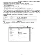
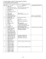
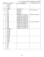
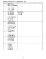
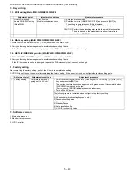
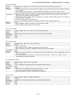
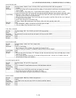
[How to use USB clone]

This is the function that copying the one TV's user setting to other TVs or copying previous user setting to itself.(Only same series.)

1. Insert the USB memory to TV.

2. Insert AC code of TV with pushing the “INPUT” and “Vol+” keys which are on the tact key.

3. Enter the passward by using R/C. The passward is “027”.

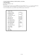
4. Select “COPY MODE”.

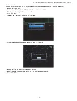
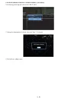
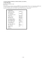
5. The follow guide is displayed. Then select the “TV

USB [Start]”.

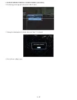
6. Follow guide is displayed when it is finished , then select "Reset" . TV will restart.

7. Insert the USB which has the data from TV to another TV or itself.

8. Insert AC code of the TV with pushing the "INPUT" and "Vol+" keys which are on the tact key.

9. Select “COPY MODE”.

Summary of Contents for AQUOS LC-52LE640U

Page 1: ...ce these parts with specified ones for maintaining the safety and performance of the set This document has been published to be used for after sales service only The contents are subject to change without notice TopPage No S12V452LE6400 LCD COLOR TELEVISION LC 52LE640U C6400U LC 60LE640U C6400U LC 70LE640U C6400U LC 80LE633U LE844U MODELS In the interests of user safety Required by safety regulati...

Page 2: ...633U 844U 4 33 CHAPTER 5 ADJUSTMENT 1 ADJUSTMENT PROCEDURE LC 52 60 70LE640U C6400U 5 1 2 ADJUSTMENT PROCEDURE LC 80LE633U 5 15 3 ADJUSTMENT PROCEDURE LC 80LE844U 5 29 4 PUBLIC MODE SETTING PROCE DURE LC 52 60 70LE640U C6400U 5 44 5 PUBLIC MODE SETTING PROCE DURE LC 80LE633U 5 52 6 PUBLIC MODE SETTING PROCE DURE LC 80LE844U 5 60 CHAPTER 6 TROUBLESHOOTING TABLE 1 Failure diagnosis by LED in front o...

Page 3: ...age drop across the resistor All checks must be repeated with the AC cord plug connection reversed If necessary a nonpolarized adaptor plug must be used only for the purpose of completing these checks Any reading of 0 75 Vrms this corresponds to 0 5 mA rms AC or more is excessive and indicates a potential shock hazard which must be corrected before returning the monitor to the owner SAFETY NOTICE ...

Page 4: ...partiment les réseaux de résistancecapacité les isolateurs mécaniques etc S assurer qu il n y ait pas de danger d électrocution en vérifiant la fuite de courant de la facon suivante Brancher le cordon d alimentation directem ent à une prise de cou rant de 120V Ne pas utiliser de transformateur d isolation pour cet essai A l aide de deux fils à pinces brancher une résistance de 1 5 kΩ 10 watts en p...

Page 5: ...the conventional lead solder by 40 C and as it has poor solder wettability you may be apt to keep the soldering bit in contact with the PWB for extended period of time However Since the land may be peeled off or the maximum heat resistance temperature of parts may be exceeded remove the bit from the PWB as soon as you confirm the steady soldering condition Lead free solder contains more tin and th...

Page 6: ...RUNTKA903WJN1 POWER LED DRIVE Unit LC 80LE633U 844U N RUNTKA819WJQZ 3D IR Unit LC 80LE844U Ref No Parts No Description N R1LK520D3GV00Z 52 LCD Panel Module Unit LC 52LE640U C6400U LK520D3GV00Z N R1LK600D3GV00Z 60 LCD Panel Module Unit LC 60LE640U C6400U LK600D3GV00Z N R1LK695D3GW80D 70 LCD Panel Module Unit LC 70LE640U C6400U LK695D3GW80D N R1LK800D3GW10Z 80 LCD Panel Module Unit LC 80LE633U LK800...

Page 7: ...LC 52 60 70LE640U C6400U LC 80LE633U 844U 1st Edition 1 1 LC52LE640U Service Manual CHAPTER 1 SPECIFICATIONS 1 SPECIFICATIONS LC 52 60 70LE640U C6400U 150 0 1 ...

Page 8: ...LC 52 60 70LE640U C6400U LC 80LE633U 844U 1st Edition 1 2 2 SPECIFICATIONS LC 80LE633U 844U ...

Page 9: ...LC 52 60 70LE640U C6400U LC 80LE633U 844U 1st Edition 1 3 ...

Page 10: ...tenna Cable in POWER button MENU button INPUT button Channel buttons CH Volume buttons VOL DIGITAL AUDIO OUTPUT terminal HDMI 3 terminal HDMI 4 terminal HDMI 1 terminal ARC Audio Return Channel AUDIO OUT terminal USB 1 terminal USB 2 terminal ETHERNET terminal HDMI 2 terminal COMPONENT terminals VIDEO 1 terminals VIDEO 2 terminals PC IN terminal 1 2 1 1 AUDIO IN terminal shared for PC IN and HDMI ...

Page 11: ...ls 17 A B C D Select 4 preset favorite channels in 4 different categories While watching you can toggle the selected channels by pressing A B C and D 18 DISPLAY Display the channel information 19 POWER SOURCE Turns the power of the external equipment on and off 20 FREEZE Set the still image Press again to return to normal screen 21 AUDIO Selects the MTS SAP or the audio mode during multichannel au...

Page 12: ...ion 4 Insert and tighten the 4 screws into the 4 holes on the rear of the TV Short screws To detach the stand perform the steps in reverse order In the installation procedure be careful not to catch your fingers between the TV set and the floor QUICK REFERENCE Attaching the Stand Before attaching or detaching the stand unplug the AC cord Before performing work spread cushioning over the base area ...

Page 13: ...LC 52 60 70LE640U C6400U LC 80LE633U 844U 1st Edition 2 4 2 OPERATION MANUAL LC 80LE633U 844U LC 80LE633U ...

Page 14: ...LC 52 60 70LE640U C6400U LC 80LE633U 844U 1st Edition 2 5 LC 80LE844U ...

Page 15: ...LC 52 60 70LE640U C6400U LC 80LE633U 844U 1st Edition 2 6 ...

Page 16: ...LC 52 60 70LE640U C6400U LC 80LE633U 844U 1st Edition 2 7 ...

Page 17: ...U 1 Active area 2 Thinnest part Unit inch mm LC 52LE640U LC 52C6400U AN 52AG4 47 9 16 1208 30 23 64 771 29 3 32 739 25 33 64 648 0 1 16 1 2 419 45 23 64 1152 0 1 13 1 8 333 5 41 64 143 2 27 32 72 1 3 64 26 4 2 2 1 64 51 13 19 32 345 15 25 64 391 5 15 3 4 400 15 3 4 400 11 17 64 286 43 64 17 8 15 32 215 21 7 64 536 4 1 2 114 6 17 64 159 ...

Page 18: ...4 136 13 1 8 333 15 3 4 400 7 31 64 190 15 3 4 400 5 25 64 137 10 23 64 263 7 59 64 201 4 34 64 115 8 15 32 215 5 18 5 32 461 20 11 64 512 21 7 64 536 29 7 16 747 63 1 52 11 32 1329 12 1 54 17 32 1385 34 11 32 872 33 1 2 839 18 1 2 470 15 3 4 400 9 1 16 230 15 3 4 400 2 1 16 52 8 15 32 215 6 9 64 156 15 9 16 395 17 13 32 442 4 17 32 115 6 21 32 169 5 5 3 4 146 13 1 8 333 2 59 64 74 1 7 64 27 9 2 L...

Page 19: ...LC 52 60 70LE640U C6400U LC 80LE633U 844U 1st Edition 3 3 3 DIMENSIONS LC 80LE633U 844U ...

Page 20: ... 1 Removing of Stand Unit and Rear Cabinet 1 Remove the 4 lock screws and detach the Stand Unit 2 Remove the 1 lock screw and detach the AC Cord Cover 3 Disconnect AC wire and detach the AC Cord 4 Remove the 4 VESA Covers 7 lock screws 16 lock screws and detach the Rear Cabinet 䎾䎤䎦䏀 䎾䎤䎦䏀 䎵䏈䏄䏕䎃䎦䏄䏅䏌䏑䏈䏗 䎹䎨䎶䎤䎃䎦䏒䏙䏈䏕 䎤䎦䎃䎦䏒䏕䏇䎃䎦䏒䏙䏈䏕 䎶䏗䏄䏑䏇䎃䎸䏑䏌䏗 䎤䎦䎃䎦䏒䏕䏇 䎔 䎙 䎕 䎚 䎘 䎖 䎗 䎛 䎜 ...

Page 21: ...ar Cabinet in place fit the hooks securely then tighten the screws Work method of Rear Cabinet fixation Front Cabinet Ass y Rear Cabinet fingernail fixation place Rear Cabinet Mat parts Front Cabinet Ass y Luster parts There is a gap without the fingernail fitting in completely only when covering with Rear Cabinet It becomes the factor of a gap increase of Front Cabinet Ass y Rear Cabinet and the ...

Page 22: ...re 4 Disconnect the RC wire 5 Detach the KEY Unit Ass y 6 Disconnect the KM wire 7 Remove the 2 lock screws and detach the Key Button from Key Button Cover 8 Detach the KEY Unit from Key Button 9 Remove the 4 Hooks and detach the 2 Bottom Cover 䎾䎮䎰䏀 䎮䎨䎼䎃䎸䏑䏌䏗 䎮䎨䎼䎃䎸䏑䏌䏗䎃䎤䏖䏖䏃䏜 䎮䏈䏜䎃䎥䏘䏗䏗䏒䏑䎃䎦䏒䏙䏈䏕 䎾䎶䎳䏀 䎾䎵䎦䏀 䎾䎶䎳䏀 䎶䏓䏈䏄䏎䏈䏕䎃䎋䎵䎌 䎶䏓䏈䏄䏎䏈䏕䎃䎋䎯䎌 䎥䏒䏗䏗䏒䏐䎃䎦䏒䏙䏈䏕 䎰䎤䎬䎱䎃䎸䏑䏌䏗 䎮䏈䏜䎃䎥䏘䏗䏗䏒䏑 䎫䏒䏒䏎 䎙 䎛 䎘 䎗 䎚 䎔 䎖 䎕 䎔 䎜 䎫䏒䏒䏎 ...

Page 23: ...the following connectors from the MAIN Unit PD LV PL Cl UB 2 Disconnect the following connectors from the POWER DRIVE Unit PD LA 3 Disconnect the following connectors from the LCD CONTROL Unit LV PL 䎰䎤䎬䎱䎃䎸䏑䏌䏗 䎾䎳䎧䏀 䎾䎳䎯䏀 䎾䎯䎹䏀 䎾䎸䎥䏀 䎾䎦䎬䏀 䎯䎦䎧䎃䎦䎲䎱䎷䎵䎲䎯䎃䎸䏑䏌䏗 䎰䎤䎬䎱䎃䎸䏑䏌䏗 䎾䎳䎧䏀 䎾䎯䎤䏀 䎾䎳䎯䏀 䎾䎯䎹䏀 䎳䎲䎺䎨䎵䎒䎧䎵䎬䎹䎨䎃䎸䏑䏌䏗 ...

Page 24: ...ews and detach the MAIN Unit and Terminal Angle Bottom 5 Remove the 6 lock screws and detach the POWER DRIVE Unit 6 Remove the 12 lock screws and detach the 2 Stand Fix Angle Ass y 7 Remove the 4 lock screws and detach the 4 VESA Angle Ass y 䎶䏗䏄䏑䏇䎃䎩䏌䏛䎃䎤䏑䏊䏏䏈 䎤䏖䏖䎊䏜 䎯䎦䎧䎃䎦䎲䎱䎷䎵䎲䎯䎃䎸䏑䏌䏗 䎦䏒䏑䏑䏈䏗䏌䏑䏊䎃䎦䏒䏕䏇 䎷䏈䏕䏐䏌䏑䏄䏏䎃䎤䏑䏊䏏䏈 䎥䏒䏗䏗䏒䏐 䎰䎤䎬䎱䎃䎸䏑䏌䏗 䎰䎤䎬䎱䎃䎳䎺䎥䎃䎶䏋䏌䏈䏏䏇 䎹䎨䎶䎤䎃䎤䏑䏊䏏䏈䎃䎤䏖䏖䏃䏜 䎳䎲䎺䎨䎵䎒䎧䎵䎬䎹䎨 䎃䎸䏑䏌䏗 䎘䎕䎅䎯䎦䎧䎃䎳䏄䏑䏈䏏䎃䎰䏒䏇䏘䏏䏈䎃䎸...

Page 25: ...C 52 60 70LE640U C6400U LC 80LE633U 844U 1st Edition 4 6 5 Removing of Center Angle 1 Remove the 12 lock screws and detach the 2 Center Angles 䎕 䎕 䎔 䎔 䎘䎕䎅䎯䎦䎧䎃䎳䏄䏑䏈䏏䎃䎰䏒䏇䏘䏏䏈䎃䎸䏑䏌䏗 䎦䏈䏑䏗䏈䏕䎃䎤䏑䏊䏏䏈䎃 䎦䏈䏑䏗䏈䏕䎃䎤䏑䏊䏏䏈䎃 ...

Page 26: ...oving of R C OPC Unit ICON Unit Wi Fi Unit 1 Detach the R C OPC Unit 2 Disconnect the RA wire 3 Detach the ICON Unit 4 Disconnect the CI wire 5 Detach the Wi Fi Unit 6 Disconnect the UB wire 䎩䏕䏒䏑䏗䎃䎦䏄䏅䏌䏑䏈䏗䎃䎤䏖䏖䏃䏜 䎺䏌䎐䎩䏌䎃䎸䏑䏌䏗 䎬䎦䎲䎱䎃䎸䏑䏌䏗 䎵䎒䎦䎃䎲䎳䎦䎃䎸䏑䏌䏗 䎾䎸䎥䏀 䎾䎦䎬䏀 䎾䎵䎤䏀 䎔 䎖 䎕 ...

Page 27: ...r cabinet If the rear cabinet is removed with the set upright the speakers may fall it results in connector disconnection Therefore never remove the rear cab inet with the set upright Be sure to remove the rear cabinet with the screen side down Precaution when mounting the rear cabinet Put the speakers in place with the screen side down and attach the rear cabinet Since the speakers are fixed by t...

Page 28: ...ar Cabinet in place fit the hooks securely then tighten the screws Work method of Rear Cabinet fixation Front Cabinet Ass y Rear Cabinet fingernail fixation place Rear Cabinet Mat parts Front Cabinet Ass y Luster parts There is a gap without the fingernail fitting in completely only when covering with Rear Cabinet It becomes the factor of a gap increase of Front Cabinet Ass y Rear Cabinet and the ...

Page 29: ...nect the RC wire 4 Detach the KEY Unit Ass y 5 Disconnect the KM wire 6 Remove the 2 lock screws and detach the Key Button from Key Button Cover 7 Detach the KEY Unit from Key Button 8 Remove the 4 Hooks and detach the 2 Bottom Cover 䎾䎮䎰䏀 䎗 䎘 䎙 䎚 䎖 䎮䎨䎼䎃䎸䏑䏌䏗 䎮䎨䎼䎃䎸䏑䏌䏗䎃䎤䏖䏖䏃䏜 䎮䏈䏜䎃䎥䏘䏗䏗䏒䏑䎃䎦䏒䏙䏈䏕 䎾䎶䎳䏀 䎾䎵䎦䏀 䎾䎶䎳䏀 䎶䏓䏈䏄䏎䏈䏕䎃䎋䎵䎌 䎶䏓䏈䏄䏎䏈䏕䎃䎋䎯䎌 䎥䏒䏗䏗䏒䏐䎃䎦䏒䏙䏈䏕 䎛 䎕 䎔 䎰䎤䎬䎱䎃䎸䏑䏌䏗 䎮䏈䏜䎃䎥䏘䏗䏗䏒䏑 䎫䏒䏒䏎 䎫䏒䏒䏎 ...

Page 30: ... the following connectors from the MAIN Unit PD LV PL Cl UB 2 Disconnect the following connectors from the POWER DRIVE Unit PD LA 3 Disconnect the following connectors from the LCD CONTROL Unit LV PL 䎾䎳䎧䏀 䎾䎳䎧䏀 䎾䎳䎯䏀 䎾䎯䎹䏀 䎾䎸䎥䏀 䎾䎦䎬䏀 䎾䎯䎤䏀 䎯䎦䎧䎃䎦䎲䎱䎷䎵䎲䎯䎃䎸䏑䏌䏗 䎰䎤䎬䎱䎃䎸䏑䏌䏗 䎳䎲䎺䎨䎵䎒䎧䎵䎬䎹䎨䎃䎸䏑䏌䏗 䎰䎤䎬䎱䎃䎸䏑䏌䏗 䎾䎳䎯䏀 䎾䎯䎹䏀 ...

Page 31: ...AIN Unit and Terminal Angle Bottom 5 Remove the 6 lock screws and detach the POWER DRIVE Unit and AC Cord Barrier 6 Remove the 12 lock screws and detach the 2 Stand Fix Angle Ass y 7 Remove the 16 lock screws and detach the 4 VESA Angle Ass y 䎔䎙 䎔䎚 䎔䎕 䎔䎔 䎔䎙 䎔䎓 䎜 䎛 䎚 䎙 䎔䎘 䎔䎗 䎘 䎗 䎔䎗 䎔䎘 䎕 䎶䏗䏄䏑䏇䎃䎩䏌䏛䎃䎤䏑䏊䏏䏈 䎃䎤䏖䏖䎊䏜 䎯䎦䎧䎃䎦䎲䎱䎷䎵䎲䎯 䎃䎸䏑䏌䏗 䎦䏒䏑䏑䏈䏗䏌䏑䏊䎃䎦䏒䏕䏇 䎷䏈䏕䏐䏌䏑䏄䏏䎃䎤䏑䏊䏏䏈 䎋䎥䏒䏗䏗䏒䏐䎌 䎰䎤䎬䎱䎃䎸䏑䏌䏗 䎰䎤䎬䎱䎃䎳䎺䎥䎃䎶䏋䏌䏈䏏䏇 䎹䎨䎶䎤䎃 䎤...

Page 32: ...oving of R C OPC Unit ICON Unit Wi Fi Unit 1 Detach the R C OPC Unit 2 Disconnect the RA wire 3 Detach the ICON Unit 4 Disconnect the CI wire 5 Detach the Wi Fi Unit 6 Disconnect the UB wire 䎩䏕䏒䏑䏗䎃䎦䏄䏅䏌䏑䏈䏗䎃䎤䏖䏖䏃䏜 䎺䏌䎐䎩䏌䎃䎸䏑䏌䏗 䎬䎦䎲䎱䎃䎸䏑䏌䏗 䎵䎒䎦䎃䎲䎳䎦䎃䎸䏑䏌䏗 䎾䎸䎥䏀 䎾䎦䎬䏀 䎾䎵䎤䏀 䎔 䎖 䎕 ...

Page 33: ...screws and detach the Rear Cabinet Ass y Precautions when mounting and removing the rear cabinet Basically there is no problem as in LC 60LE632U However the screws on both sides are not tightened together with the Rear Cabinet Ass y The inside is fixed by the module and Speaker Therefore it does not come away completely but only one side can come off 䎾䎤䎦䏀 䎾䎤䎦䏀 䎕 䎚 䎙 䎘 䎗 䎖 䎜 䎛 䎵䏈䏄䏕䎃䎦䏄䏅䏌䏑䏈䏗䎃䎤䏖䏖䏃䏜 䎹䎨...

Page 34: ...Push Push Push Push Push Push Push Push CAUTION Set it so that there may not be a clearance between Front Cabinet Ass y and Rear Cabinet Ass y There is a gap without the fingernail fitting in completely only when covering with Rear Cabinet Ass y The fingernail is surely fixed when Rear cabinet Ass y is firmly pushed and the gap disappears 19 places ...

Page 35: ...isconnect the RC wire 4 Detach the KEY Unit Ass y 5 Disconnect the KM wire 6 Remove the 2 lock screws and detach the Key Button from Key Button Cover 7 Detach the KEY Unit from Key Button 8 Remove the 4 Hooks and detach the 2 Bottom Cover 䎾䎮䎰䏀 䎘 䎙 䎚 䎛 䎗 䎮䏈䏜䎃䎥䏘䏗䏗䏒䏑 䎮䎨䎼䎃䎸䏑䏌䏗 䎮䎨䎼䎃䎸䏑䏌䏗䎃䎤䏖䏖䏃䏜 䎮䏈䏜䎃䎥䏘䏗䏗䏒䏑䎃䎦䏒䏙䏈䏕 䎾䎶䎳䏀 䎶䏓䏈䏄䏎䏈䏕䎃䎋䎵䎌 䎶䏓䏈䏄䏎䏈䏕䎃䎋䎯䎌 䎥䏒䏗䏗䏒䏐䎃䎦䏒䏙䏈䏕 䎜 䎜 䎖 䎕 䎰䎤䎬䎱䎃䎸䏑䏌䏗 䎔 䎫䏒䏒䏎 䎫䏒䏒䏎 䎔 䎾䎶䎳䏀 䎾䎵䎦䏀 ...

Page 36: ... the following connectors from the MAIN Unit PD LV PL Cl UB 2 Disconnect the following connectors from the POWER DRIVE Unit PD LA 3 Disconnect the following connectors from the LCD CONTROL Unit LV PL 䎾䎳䎧䏀 䎾䎳䎧䏀 䎾䎳䎯䏀 䎾䎯䎹䏀 䎾䎸䎥䏀 䎾䎦䎬䏀 䎾䎯䎤䏀 䎯䎦䎧䎃䎦䎲䎱䎷䎵䎲䎯䎃䎸䏑䏌䏗 䎰䎤䎬䎱䎃䎸䏑䏌䏗 䎳䎲䎺䎨䎵䎒䎧䎵䎬䎹䎨䎃䎸䏑䏌䏗 䎰䎤䎬䎱䎃䎸䏑䏌䏗 䎾䎳䎯䏀 䎾䎯䎹䏀 ...

Page 37: ...e the 5 lock screws and detach the MAIN PWB Shield 6 Remove the 3 lock screws and detach the MAIN Unit and Terminal Angle Bottom 7 Remove the 12 lock screws and detach the 2 Stand Fix Angle Ass y 8 Remove the 16 lock screws and detach the 4 VESA Angle Ass y 䎔䎚 䎔䎛 䎔䎚 䎔䎚 䎔䎚 䎔䎛 䎜 䎛 䎔䎗 䎔䎖 䎔䎕 䎔䎔 䎔䎓 䎔䎙 䎔䎘 䎘 䎗 䎔䎘 䎔䎙 䎕 䎶䏗䏄䏑䏇䎃䎩䏌䏛䎃䎤䏑䏊䏏䏈 䎃䎤䏖䏖䎊䏜 䎯䎦䎧䎃䎦䎲䎱䎷䎵䎲䎯䎃䎸䏑䏌䏗 䎦䏒䏑䏑䏈䏗䏌䏑䏊䎃䎦䏒䏕䏇 䎷䏈䏕䏐䏌䏑䏄䏏䎃䎤䏑䏊䏏䏈 䎋䎥䏒䏗䏗䏒䏐䎌 䎰䎤䎬䎱䎃䎸䏑䏌...

Page 38: ...oving of R C OPC Unit ICON Unit Wi Fi Unit 1 Detach the R C OPC Unit 2 Disconnect the RA wire 3 Detach the ICON Unit 4 Disconnect the CI wire 5 Detach the Wi Fi Unit 6 Disconnect the UB wire 䎩䏕䏒䏑䏗䎃䎦䏄䏅䏌䏑䏈䏗䎃䎤䏖䏖䏃䏜 䎺䏌䎐䎩䏌䎃䎸䏑䏌䏗 䎬䎦䎲䎱䎃䎸䏑䏌䏗 䎵䎒䎦䎃䎲䎳䎦䎃䎸䏑䏌䏗 䎾䎸䎥䏀 䎾䎦䎬䏀 䎾䎵䎤䏀 䎔 䎖 䎕 ...

Page 39: ... detach the Stand Unit 2 Remove the 10 lock screws and 26 lock screws and detach the Rear Cabinet Precautions when mounting and removing the rear cabinet Therefore it does not come away completely but only one side can come off 2 Stand Unit Rear Cabinet 8 1 3 4 4 4 Tighten together with the Rear Cabinet Ass y Fix with the 80 LCD Panel Module Unit Only one side outer can come off ...

Page 40: ...sons Do following works as 1 Please grasp the swelling of a speaker and pull back with pushing down Remove one hook under an operation 2 Put a hand in terminal area and pulls back and the other hand holds top side of TV set Remove all right hand side hook 2WV C JCPF DGVYGGP VGTOKPCN CPING CPF 4GCT CDKPGV UU CPF RWNNU VJGO DCEM ...

Page 41: ...her hand between bottom cover and Rear Cabinet Ass y And pull Rear Cabinet Ass y Remove all left hand side hook 4 Two persons stand on the both sides of TV SET and have a Front Cabinet Ass y and a Rear Cabinet Ass y by each hand Two persons pull a Rear Cabinet Ass y horizontally back simultaneously and remove it ...

Page 42: ...lace Push Push Push Push Push Push Push Push CAUTION Set it so that there may not be a clearance between Front Cabinet Ass y and Rear Cabinet Ass y There is a gap without the fingernail fitting in completely only when covering with Rear Cabinet Ass y The fingernail is surely fixed when Rear cabinet Ass y is firmly pushed and the gap disappears ...

Page 43: ...ach the KEY Unit Ass y 5 Disconnect the KM wire 6 Remove the 2 lock screws and detach the Key Button from Key Button Cover 7 Detach the KEY Unit from Key Button How to remove KEY Unit Ass y 1 When you remove KEY Unit Ass y please be sure to remove harness from WH and to hold the bottom of KEY Unit Ass y 7 5 4 8 6 Key Button KEY Unit KEY Unit Ass y Key Button Cover SP KM SP RC MAIN Unit 3 1 Speaker...

Page 44: ...connect the following connectors from the POWER LED DRIVE Unit L1 L2 PD 3 Disconnect the following connectors from the LCD Control Unit PL LW 4 Remove the 27 Hooks and detach the 80 LCD Panel Module Unit Ass y 5 Detach the 2 Bottom cover PD UB CI LV MAIN Unit LCD Control Unit POWER LED DRIVE Unit Hock Hock Hock Hock L1 L2 PD PL LW 1 80 LCD Panel Module Unit Ass y MAIN Unit 2 Bottom cover ...

Page 45: ...ach the MAIN Unit and Terminal Angle Bottom 4 Remove the 6 lock screws and detach the POWER LED DRIVE Unit 5 Remove the 12 lock screws and detach the 2 Stand Angles 6 Remove the 16 lock screws and detach the 4 VESA Angle Ass ys 80 LCD Panel Module Unit 11 10 1 FFC LCD Control Unit 12 3 13 12 POWER LED DRIVE Unit Stand Angle 13 Stand Angle 8 5 4 Terminal Angle Bottom 7 Shield MAIN Unit 6 MAIN Unit ...

Page 46: ...t ICON Unit Wi Fi Unit 1 Detach the R C OPC Unit 2 Disconnect the RC wire 3 Detach the ICON Unit 4 Disconnect the CI wire 5 Detach the Wi Fi Unit 6 Disconnect the UB wire 7 Detach the WiFi Attachment Front Cabinet Ass y 3 ICON Unit 2 Wi Fi Unit 1 R C OPE Unit RA UB CI 4 WiFi Attachment ...

Page 47: ... 5 The location putting on the heat measure sheet LC 52 60 70LE640U C6400U 1 MAIN PWB Unit LC 52 60LE640U C6400U LC 70LE640U 6400U 2 LCD Control Unit LC 60LE640U C6400U Put 䇼PSPAZC805WJKZ䇽 along these ruled lines PSPAZC741WJKZ 835 PSPAZC854WJKZ TCON CPU COOLER ...

Page 48: ...LC 52 60 70LE640U C6400U LC 80LE633U 844U 1st Edition 4 29 6 The location putting on the heat measure sheet LC 80LE844U 1 MAIN PWB Unit PSPAZC741WJKZ PSPAZC835WJKZ ...

Page 49: ...ain PWB Ass y on the backlight chassis and check that the EMI prevention parts are not peeled and twisted from the access holes The EMI prevention parts conductive nonwoven fabric gaskets must be seen from the access holes Countermeasure Attach the conductive nonwoven fabric gaskets on the shielded case on the main PWB LC 52 60LE640U C6400U PSPAZC690WJZZ PSPAZC691WJZZ x2 PSPAZC691WJZZ ...

Page 50: ...LC 52 60 70LE640U C6400U LC 80LE633U 844U 1st Edition 4 31 LC 70LE640U C6400U PMLT A691WJQZ PMLT A690WJQZ PMLT A690WJQZ 4 Stick PSPAZC740WJZZ CONDUCTR 9x146 PMLT A691WJQZ ...

Page 51: ... shielded case are assembled The following is a drawing mounting the main PWB Ass y on the backlight chassis The parts indicated by are the access holes for confirmation Main PWB Ass y State where the shielded case and RF terminal angle are mounted on the main PWB Access hole Access hole ...

Page 52: ... are not peeled and twisted from the access holes The EMI prevention parts conductive nonwoven fabric gaskets must be seen from the access holes Countermeasure Attach the conductive nonwoven fabric gaskets on the shielded case on the main PWB State where the main PWB and shielded case are assembled PMLT A678WJQZ x 2 pcs PMLT A679WJQZ PSPAZC740WJZZ Attach the conductive nonwoven fabric gasket on th...

Page 53: ...Edition 4 34 The following is a drawing mounting the main PWB Ass y on the backlight chassis The parts indicated by are the access holes for confirmation Main PWB Ass y State where the shielded case and RF terminal angle are mounted on the main PWB ...

Page 54: ...processor software please use a software version after BM2SMxxx SMB The main software monitor microprocessor software can be upgraded by using a general purpose USB Memory The followings are the procedures for upgrading explained separately for the main software monitor microprocessor software 2 2 Main software version upgrade 2 2 1 Get ready before you start USB Memory of 128MB or higher capacity...

Page 55: ...s You can check the new software version on this screen The version information appears after the upgrade is complete 8 Unplug the AC cord and remove the USB Memory for version upgrade 9 Now the software version upgrade is complete NOTE When you are done with the software version upgrade start the set go to the top page of the adjustment process screen and check the main software version informati...

Page 56: ...ill blink continuously Also an upgrade screen will be shown during a minor upgrade 6 If the upgrade fails power led will stop blinking Also the upgrade failure screen will be shown if upgrade screen was shown at 5 NOTE In the event of a transient failure upgrade will be automatically retried up to three times If the process repeatedly fails hardware may be the cause 7 The upgrade success screen wi...

Page 57: ...he adjustment process mode If the settings are tampered in this mode unrecoverable system damage may result 4 Remote controller key operation and description of display in adjustment process mode 1 Key operation Input mode is switched automatically when relevant adjustment is started so far as the necessary input signal is available 2 Description of display Remote controller key Main unit key Func...

Page 58: ...e setting for VIC READ 10 VIC YPOS Y coordinate setting for VIC READ 11 VIC COLOR Collected color data setting for VIC READ 12 VIC SIGNAL TYPE Signal type setting for VIC READ 13 VIC READ Picture level acquisition function Level appears in green on the upper right 3 1 N358 ALL ADJ INPUT2 CVBS and TUNER signal level adjustment 2 N358 MAIN ADJ INPUT2 CVBS signal level adjustment 3 TUNER DAC ADJ TUNE...

Page 59: ...t value 7 MG3R WB adjustment Point 3 R adjustment value 8 MG3G WB adjustment Point 3 G adjustment value 9 MG3B WB adjustment Point 3 B adjustment value 11 1 MG4R WB adjustment Point 4 R adjustment value Parameter for six point adjustment 2 MG4G WB adjustment Point 4 G adjustment value 3 MG4B WB adjustment Point 4 B adjustment value 4 MG5R WB adjustment Point 5 R adjustment value 5 MG5G WB adjustme...

Page 60: ... TEST PATTERN4 6 TV TEST PATTERN 1 7 TV TEST PATTERN 2 19 1 T CON VERSION EXT 1 PRIMROSE 2D Version 2 T CON VERSION EXT 2 PRIMROSE 3D Version 3 T CON VERSION EXT 3 Blank Not Use 4 T CON VERSION EXT 4 Blank Not Use 20 1 READ WRITE 2 SLAVE ADDRESS 3 RESISTER ADDRESS UPPER 4 RESISTER ADDRESS LOWER 5 WRITE DATA UPPER 6 WRITE DATA LOWER 7 READ DATA UPPER 8 READ DATA LOWER 21 1 POWER LED BRIGHTNESS 2 ME...

Page 61: ...ID 3 WIFI RSSI 2 4GHz Set RSSI threshold 4 WIFI RSSI 5GHz Set RSSI threshold 5 WIFI TIME 2 4GHz Set Time Out 6 WIFI TIME 5GHz Set Time Out 7 WIFI RSSI TEST Execute test 8 WIFI RSSI RESULT Display test result 26 1 KEY LOCK 1217 2 KOUTEI AREA ALL CLEAR 3 A MODE AREA CLEAR 4 BACKUP AREA CLEAR 5 B MODE AREA CLEAR 6 EXECUTION 27 1 ERROR STANDBY CAUSE1 2 ERROR STANDBY CAUSE2 3 ERROR STANDBY CAUSE3 4 ERR...

Page 62: ...etup Reset 50 E_TCNF_S T CON FPGA status error 54 E_TCON_E T CON hung up Monitor ERR STBY table Outline Communication Power failure detected by the monitor microprocessor is stored in EEPROM and last 4 abnormal can be confirmed in the Process mode A Location Page 1 of the process mode A MONITOR ERR CAUSE 0 if there is no error It is cleared to 0 on the last page of the process mode A Display Error...

Page 63: ...8461 TL8475 2 Using the checker connect the USB memory to the J9502 TL9503 TL9506 9508 3 Apply the specified voltage to the PWB and boot it up with the tool connected 4 Send the software writing start command via RS232C 5 Send the writing status check command and confirm the response of OK Then turn off the power CAUTION When the USB memory is not inserted or reading error occurs nothing is writte...

Page 64: ...procedure Process mode Enter the process adjustment mode using the process adjustment remote control Adjustment point Adjustment conditions Adjustment procedure 1 Setting N358 signal US 10ch Send the N358 color bar color saturation 75 signal to the composite input Send the in house signal use US 10ch to TUNER 2 Automatic adjustment exe cution Point the cursor to N358 ALL ADJ INPUT2 and press the E...

Page 65: ...tting Signal XGA 1024x768 60Hz SYNC HV separate Send the 100 color bar signal to the PC input 2 Automatic adjustment exe cution Point the cursor to ANALOG RGB ADJ and press the Enter key The adjustment is complete when ANALOG RGB ADJ OK is displayed Adjustment point Adjustment conditions Adjustment procedure 1 Setting NTSC RF signal US 7 AIR ch Send the NTSC signal to the RF antenna input 2 Automa...

Page 66: ...he point 3 to the specified gradation set the G correction value 480 x G value of point 6 928 fractions rounded off and adjust the RB so that it becomes the standard value 6 Set the point 2 to the specified gradation set the G correction value 236 x G value of point 6 928 fractions rounded off and adjust the RB so that it becomes the standard value 7 Set the point 1 to the specified gradation set ...

Page 67: ...complete the setting CAUTION Do not turn on the power after completing the factory setting If the power is turned on configure the factory setting again 12 Software version 1 Main microprocessor BSMK_LE640_xxx USB BSMK_LE640_xxx DAT 2 Monitor microprocessor BM2SMxxx SMB 13 Writing the inch and model name onto EEPROM LE640U C6400U 1 Enter the adjustment process mode 2 Point the cursor to MODEL NAME...

Page 68: ...ase use a software version after BM2SMxxx SMB The main software monitor microprocessor software can be upgraded by using a general purpose USB Memory The followings are the procedures for upgrading explained separately for the main software monitor microprocessor software 2 2 Main software version upgrade 2 2 1 Get ready before you start USB Memory of 128MB or higher capacity PC running on Windows...

Page 69: ...rs You can check the new software version on this screen The version information appears after the upgrade is complete 8 Unplug the AC cord and remove the USB Memory for version upgrade 9 Now the software version upgrade is complete NOTE When you are done with the software version upgrade start the set go to the top page of the adjustment process screen and check the main software version informat...

Page 70: ...k continuously Also an upgrade screen will be shown during a minor upgrade 6 If the upgrade fails power led will stop blinking Also the upgrade failure screen will be shown if upgrade screen was shown at 5 NOTE In the event of a transient failure upgrade will be automatically retried up to three times If the process repeatedly fails hardware may be the cause 7 The upgrade success screen will be sh...

Page 71: ...he adjustment process mode If the settings are tampered in this mode unrecoverable system damage may result 4 Remote controller key operation and description of display in adjustment process mode 1 Key operation Input mode is switched automatically when relevant adjustment is started so far as the necessary input signal is available 2 Description of display Remote controller key Main unit key Func...

Page 72: ...e setting for VIC READ 10 VIC YPOS Y coordinate setting for VIC READ 11 VIC COLOR Collected color data setting for VIC READ 12 VIC SIGNAL TYPE Signal type setting for VIC READ 13 VIC READ Picture level acquisition function Level appears in green on the upper right 3 1 N358 ALL ADJ INPUT2 CVBS and TUNER signal level adjustment 2 N358 MAIN ADJ INPUT2 CVBS signal level adjustment 3 TUNER DAC ADJ TUNE...

Page 73: ...nt value 7 MG3R WB adjustment Point 3 R adjustment value 8 MG3G WB adjustment Point 3 G adjustment value 9 MG3B WB adjustment Point 3 B adjustment value 11 1 MG4R WB adjustment Point 4 R adjustment value Parameter for six point adjustment 2 MG4G WB adjustment Point 4 G adjustment value 3 MG4B WB adjustment Point 4 B adjustment value 4 MG5R WB adjustment Point 5 R adjustment value 5 MG5G WB adjustm...

Page 74: ... TEST PATTERN4 6 TV TEST PATTERN 1 7 TV TEST PATTERN 2 19 1 T CON VERSION EXT 1 PRIMROSE 2D Version 2 T CON VERSION EXT 2 PRIMROSE 3D Version 3 T CON VERSION EXT 3 Blank Not Use 4 T CON VERSION EXT 4 Blank Not Use 20 1 READ WRITE 2 SLAVE ADDRESS 3 RESISTER ADDRESS UPPER 4 RESISTER ADDRESS LOWER 5 WRITE DATA UPPER 6 WRITE DATA LOWER 7 READ DATA UPPER 8 READ DATA LOWER 21 1 POWER LED BRIGHTNESS 2 ME...

Page 75: ...ID 3 WIFI RSSI 2 4GHz Set RSSI threshold 4 WIFI RSSI 5GHz Set RSSI threshold 5 WIFI TIME 2 4GHz Set Time Out 6 WIFI TIME 5GHz Set Time Out 7 WIFI RSSI TEST Execute test 8 WIFI RSSI RESULT Display test result 26 1 KEY LOCK 1217 2 KOUTEI AREA ALL CLEAR 3 A MODE AREA CLEAR 4 BACKUP AREA CLEAR 5 B MODE AREA CLEAR 6 EXECUTION 27 1 ERROR STANDBY CAUSE1 2 ERROR STANDBY CAUSE2 3 ERROR STANDBY CAUSE3 4 ERR...

Page 76: ...etup Reset 50 E_TCNF_S T CON FPGA status error 54 E_TCON_E T CON hung up Monitor ERR STBY table Outline Communication Power failure detected by the monitor microprocessor is stored in EEPROM and last 4 abnormal can be confirmed in the Process mode A Location Page 1 of the process mode A MONITOR ERR CAUSE 0 if there is no error It is cleared to 0 on the last page of the process mode A Display Error...

Page 77: ...8461 TL8475 2 Using the checker connect the USB memory to the J9502 TL9503 TL9506 9508 3 Apply the specified voltage to the PWB and boot it up with the tool connected 4 Send the software writing start command via RS232C 5 Send the writing status check command and confirm the response of OK Then turn off the power CAUTION When the USB memory is not inserted or reading error occurs nothing is writte...

Page 78: ...procedure Process mode Enter the process adjustment mode using the process adjustment remote control Adjustment point Adjustment conditions Adjustment procedure 1 Setting N358 signal US 10ch Send the N358 color bar color saturation 75 signal to the composite input Send the in house signal use US 10ch to TUNER 2 Automatic adjustment exe cution Point the cursor to N358 ALL ADJ INPUT2 and press the E...

Page 79: ...tting Signal XGA 1024x768 60Hz SYNC HV separate Send the 100 color bar signal to the PC input 2 Automatic adjustment exe cution Point the cursor to ANALOG RGB ADJ and press the Enter key The adjustment is complete when ANALOG RGB ADJ OK is displayed Adjustment point Adjustment conditions Adjustment procedure 1 Setting NTSC RF signal US 7 AIR ch Send the NTSC signal to the RF antenna input 2 Automa...

Page 80: ...he point 3 to the specified gradation set the G correction value 480 x G value of point 6 928 fractions rounded off and adjust the RB so that it becomes the standard value 6 Set the point 2 to the specified gradation set the G correction value 236 x G value of point 6 928 fractions rounded off and adjust the RB so that it becomes the standard value 7 Set the point 1 to the specified gradation set ...

Page 81: ...complete the setting CAUTION Do not turn on the power after completing the factory setting If the power is turned on configure the factory setting again 12 Software version 1 Main microprocessor BSMK_LE640_xxx USB BSMK_LE640_xxx DAT 2 Monitor microprocessor BM2SMxxx SMB 13 Writing the inch and model name onto EEPROM LE640U C6400U 1 Enter the adjustment process mode 2 Point the cursor to MODEL NAME...

Page 82: ...e please use a software version after BMSDMxxx SMB The main software monitor microprocessor software can be upgraded by using a general purpose USB Memory The followings are the procedures for upgrading explained separately for the main software monitor microprocessor software 2 2 Main software version upgrade 2 2 1 Get ready before you start USB Memory of 128MB or higher capacity PC running on Wi...

Page 83: ...n this screen The version information appears after the upgrade is complete 8 Unplug the AC cord and remove the USB Memory for version upgrade 9 Now the software version upgrade is complete NOTE When you are done with the software version upgrade start the set go to the top page of the adjustment process screen and check the main software version information MAIN SUB MICOM PANEL EEPROM IR MICOM MA...

Page 84: ... be shown during a minor upgrade 6 If the upgrade fails power led will stop blinking Also the upgrade failure screen will be shown if upgrade screen was shown at 5 NOTE In the event of a transient failure upgrade will be automatically retried up to three times If the process repeatedly fails hardware may be the cause 7 The upgrade success screen will be shown if upgrade screen was shown at 5 8 Unp...

Page 85: ... process mode If the settings are tampered in this mode unrecoverable system damage may result 4 Remote controller key operation and description of display in adjustment process mode 1 Key operation Input mode is switched automatically when relevant adjustment is started so far as the necessary input signal is available 2 Description of display Remote controller key Main unit key Function CH CH Mo...

Page 86: ...C XPOS X coordinate setting for VIC READ 10 VIC YPOS Y coordinate setting for VIC READ 11 VIC COLOR Collected color data setting for VIC READ 12 VIC SIGNAL TYPE Signal type setting for VIC READ 13 VIC READ Picture level acquisition function Level appears in green on the upper right 3 1 N358 MAIN ADJ INPUT2 CVBS and TUNER signal level adjustment 2 N358 MAIN ADJ INPUT2 CVBS signal level adjustment 3...

Page 87: ...R WB adjustment Point 3 R adjustment value 8 MG3G WB adjustment Point 3 G adjustment value 9 MG3B WB adjustment Point 3 B adjustment value 11 1 MG4R WB adjustment Point 4 R adjustment value Parameter for six point adjustment 2 MG4G WB adjustment Point 4 G adjustment value 3 MG4B WB adjustment Point 4 B adjustment value 4 MG5R WB adjustment Point 5 R adjustment value 5 MG5G WB adjustment Point 5 G ...

Page 88: ...RIGHTNESS 2 MENU LED BRIGHTNESS 3 INPUT LED BRIGHTNESS 4 CH UP LED BRIGHTNESS 5 CH DOWN LED BRIGHTNESS 6 VOL UP LED BRIGHTNESS 7 VOL DOWN LED BRIGHTNESS 8 LOGO LED BRIGHTNESS 9 ICON LED BRIGHTNESS 10 ICON LED BRIGHTNESS STANDBY 11 3D LED BRIGHTNESS 20 1 POWER KEY SENSITIVITY 2 MENU KEY SENSITIVITY 3 INPUT KEY SENSITIVITY 4 CH UP KEY SENSITIVITY 5 CH DOWN KEY SENSITIVITY 6 VOL UP KEY SENSITIVITY 7 ...

Page 89: ... KOUTEI AREA ALL CLEAR 3 A MODE AREA CLEAR 4 BACKUP AREA CLEAR 5 B MODE AREA CLEAR 6 EXECUTION 25 1 ERROR STANDBY CAUSE1 2 ERROR STANDBY CAUSE2 3 ERROR STANDBY CAUSE3 4 ERROR STANDBY CAUSE4 5 ERROR STANDBY CAUSE5 6 ERROR STANDBY CAUSE RESET 26 1 EEP SAVE Writing setting values to EEPROM 2 EEP RECOVER Reading setting values from EEPROM 3 MODEL NAME 4 PANEL SIZE 5 SETTING FOR ADJ 6 PANEL LIMIT 7 PAN...

Page 90: ..._S T CON FPGA status error 54 E_TCON_E T CON hung up Monitor ERR STBY table Outline Communication Power failure detected by the monitor microprocessor is stored in EEPROM and last 4 abnormal can be confirmed in the Process mode A Location Page 1 of the process mode A MONITOR ERR CAUSE 0 if there is no error It is cleared to 0 on the last page of the process mode A Display Error description 02 Init...

Page 91: ...8 2 Using the checker connect the USB memory to the J9502 TL9524 9527 3 Apply the specified voltage to the PWB and boot it up with the tool connected 4 Send the software writing start command via RS232C 5 Send the writing status check command and confirm the response of OK Then turn off the power CAUTION When the USB memory is not inserted or reading error occurs nothing is written Adjustment item...

Page 92: ...2Vp p Analog RGB RGB level 0 7Vp p 0 02Vp p Pedestal to white Adjustment point Adjustment conditions Adjustment procedure Process mode Enter the process adjustment mode using the process adjustment remote control Adjustment point Adjustment conditions Adjustment procedure 1 Setting N358 signal US 10ch Send the N358 color bar color saturation 75 signal to the composite input Send the in house signa...

Page 93: ... Adjustment conditions Adjustment procedure 1 Setting Signal XGA 1024x768 60Hz SYNC HV separate Send the 100 color bar signal to the PC input 2 Automatic adjustment exe cution Point the cursor to ANALOG RGB ADJ and press the Enter key The adjustment is complete when ANALOG RGB ADJ OK is displayed Adjustment point Adjustment conditions Adjustment procedure 1 Setting NTSC RF signal US 7 AIR ch Send ...

Page 94: ...792 x G value of point 6 928 fractions rounded off and the Ye correction value 792 x Ye value of point 6 928 fractions rounded off then adjust RB so that it becomes the standard value 4 Set the point 4 to the specified gradation and set the G correction value 608 x G value of point 6 928 fractions rounded off and the Ye correction value 608 x Ye value of point 6 928 fractions rounded off then adju...

Page 95: ...20 y 0 277 Point 2 Point 4 608 X 0 272 0 0015 0 0030 LEV20066 y 0 277 MG2G Point 3 348 X 0 272 0 0020 0 0040 MG2B y 0 277 MG2R Point 2 264 X 0 272 0 0030 0 0060 MG2Y y 0 277 Point 1 180 X 0 272 0 004 0 0080 Point 1 y 0 277 LEV10045 MG1G MG1B MG1R MG1Y Writing MSET0003 Remarks Setting conditions for inspection AV MODE DYNAMIC Reset Monochro ON Active Backlight OFF Aging Time Min 60 minutes Brightne...

Page 96: ...r microprocessor 3 LCD Controller Adjustment point Adjustment conditions Adjustment procedure HDMI EDID writing Analog RGB EDID writing Main PWB Process mode Model discrimination check 1 Enter the process mode 2 Point the cursor to HDMI EDID WRITE and press the ENT key The writing is complete when OK is displayed If not written HDMI and Analog RGB does not function CAUTION Perform the data writing...

Page 97: ...n changes to the normal mode 2 How to exit Public Mode There are the following ways to quit the public mode setup screen Turn off PUBLIC MODE in the adjustment process mode This way alone is not for quitting the setup screen but for quitting the mode itself Turn off the power with the POWER key Select EXECUTE PUBLIC MODE stays on in the adjustment process mode The settings will be back to the fact...

Page 98: ...y remote controller and VOL key remote controller and set To save new settings keep the cursor at EXECUTE and use ENTER key remote controller and set PUBLIC MODE POWER ON FIXED VARIABLE MAXIMUM VOLUME 60 VOLUME FIXED VARIABLE VOLUME FIXED LEVEL 20 RC BUTTON RESPOND PANEL BUTTON RESPOND MENU BUTTON RESPOND AV POSITION FIXED VARIABLE ON SCREEN DISPLAY YES INPUT MODE START NORMAL INPUT MODE FIXED VAR...

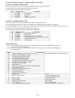
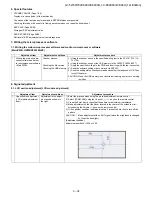
Page 99: ... of TV with pushing the INPUT and Vol keys which are on the tact key 3 Enter the passward by using R C The passward is 027 4 Select COPY MODE 5 The follow guide is displayed Then select the TV USB Start 6 Follow guide is displayed when it is finished then select Reset TV will restart 7 Insert the USB which has the data from TV to another TV or itself 8 Insert AC code of the TV with pushing the INP...

Page 100: ...00U LC 80LE633U 844U 1st Edition 5 47 10 The following guide is dispalyed Then select the USB TV Start 11 Follow guide is displayed when it is finished then select Reset TV will restart 12 Comfirm the user setting is copied ...

Page 101: ...rt up at the level specified for a fixed volume at start Limit in Setting The sound volume for the ON timer Wake up timer is fixed also without display of menu Besides the setting is made impossible Basically the menu is not displayed The following keys become invalid Sound volume Up Down VOL for both remote control and the unit Mute MUTE Exception In the item VOLUME of adjustment process the soun...

Page 102: ... alone cannot be displayed This is because the channel call message may be confused with a message being sent from the hotel On the North America destined models the OSD works the same as at the No setting Limit in Setting Keys falling under any of the following items become invalid Appearance of screen changes and the sound changes Personal functions which are hard to restore Screen display menu ...

Page 103: ... Normal Selection Selection between OFF ON TV RCE and ON TV RCD loop provided Default OFF Explanation Function to feed the remote controller received signal to Pin 9 open on the RS232C Limit in Setting None Exception None Remarks None Selection Selection between Variable and Fixed loop provided Default Variable Explanation In case of Fixed setting Menu Picture and Audio setting can t be changed li...

Page 104: ...5 PUBLIC MODE ON OFF Selection Selection between ON and OFF loop provided Default OFF Explanation In case of ON public mode settings are effected Limit in Setting None Exception None Remarks The public mode settings are operable only when this item is set at ON ...

Page 105: ...es to the normal mode 2 How to exit Public Mode There are the following ways to quit the public mode setup screen Turn off PUBLIC MODE in the adjustment process mode This way alone is not for quitting the setup screen but for quitting the mode itself Turn off the power with the POWER key Select EXECUTE PUBLIC MODE stays on in the adjustment process mode The settings will be back to the factory one...

Page 106: ...y remote controller and VOL key remote controller and set To save new settings keep the cursor at EXECUTE and use ENTER key remote controller and set PUBLIC MODE POWER ON FIXED VARIABLE MAXIMUM VOLUME 60 VOLUME FIXED VARIABLE VOLUME FIXED LEVEL 20 RC BUTTON RESPOND PANEL BUTTON RESPOND MENU BUTTON RESPOND AV POSITION FIXED VARIABLE ON SCREEN DISPLAY YES INPUT MODE START NORMAL INPUT MODE FIXED VAR...

Page 107: ... of TV with pushing the INPUT and Vol keys which are on the tact key 3 Enter the passward by using R C The passward is 027 4 Select COPY MODE 5 The follow guide is displayed Then select the TV USB Start 6 Follow guide is displayed when it is finished then select Reset TV will restart 7 Insert the USB which has the data from TV to another TV or itself 8 Insert AC code of the TV with pushing the INP...

Page 108: ...00U LC 80LE633U 844U 1st Edition 5 55 10 The following guide is dispalyed Then select the USB TV Start 11 Follow guide is displayed when it is finished then select Reset TV will restart 12 Comfirm the user setting is copied ...

Page 109: ...rt up at the level specified for a fixed volume at start Limit in Setting The sound volume for the ON timer Wake up timer is fixed also without display of menu Besides the setting is made impossible Basically the menu is not displayed The following keys become invalid Sound volume Up Down VOL for both remote control and the unit Mute MUTE Exception In the item VOLUME of adjustment process the soun...

Page 110: ... alone cannot be displayed This is because the channel call message may be confused with a message being sent from the hotel On the North America destined models the OSD works the same as at the No setting Limit in Setting Keys falling under any of the following items become invalid Appearance of screen changes and the sound changes Personal functions which are hard to restore Screen display menu ...

Page 111: ... Normal Selection Selection between OFF ON TV RCE and ON TV RCD loop provided Default OFF Explanation Function to feed the remote controller received signal to Pin 9 open on the RS232C Limit in Setting None Exception None Remarks None Selection Selection between Variable and Fixed loop provided Default Variable Explanation In case of Fixed setting Menu Picture and Audio setting can t be changed li...

Page 112: ...5 PUBLIC MODE ON OFF Selection Selection between ON and OFF loop provided Default OFF Explanation In case of ON public mode settings are effected Limit in Setting None Exception None Remarks The public mode settings are operable only when this item is set at ON ...

Page 113: ...es to the normal mode 2 How to exit Public Mode There are the following ways to quit the public mode setup screen Turn off PUBLIC MODE in the adjustment process mode This way alone is not for quitting the setup screen but for quitting the mode itself Turn off the power with the POWER key Select EXECUTE PUBLIC MODE stays on in the adjustment process mode The settings will be back to the factory one...

Page 114: ...FT key remote controller and VOL key remote controller and set To save new settings keep the cursor at EXECUTE and use ENTER key remote controller and set PUBLIC MODE POWER ON FIXED VARIABLE MAXIMUM VOLUME 60 VOLUME FIXED VARIABLE VOLUME FIXED LEVEL 20 RC BUTTON RESPOND PANEL BUTTON RESPOND MENU BUTTON RESPOND AV POSITION FIXED VARIABLE ON SCREEN DISPLAY YES INPUT MODE START NORMAL INPUT MODE FIXE...

Page 115: ...rt up at the level specified for a fixed volume at start Limit in Setting The sound volume for the ON timer Wake up timer is fixed also without display of menu Besides the setting is made impossible Basically the menu is not displayed The following keys become invalid Sound volume Up Down VOL for both remote control and the unit Mute MUTE Exception In the item VOLUME of adjustment process the soun...

Page 116: ... alone cannot be displayed This is because the channel call message may be confused with a message being sent from the hotel On the North America destined models the OSD works the same as at the No setting Limit in Setting Keys falling under any of the following items become invalid Appearance of screen changes and the sound changes Personal functions which are hard to restore Screen display menu ...

Page 117: ... Normal Selection Selection between OFF ON TV RCE and ON TV RCD loop provided Default OFF Explanation Function to feed the remote controller received signal to Pin 9 open on the RS232C Limit in Setting None Exception None Remarks None Selection Selection between Variable and Fixed loop provided Default Variable Explanation In case of Fixed setting Menu Picture and Audio setting can t be changed li...

Page 118: ...5 PUBLIC MODE ON OFF Selection Selection between ON and OFF loop provided Default OFF Explanation In case of ON public mode settings are effected Limit in Setting None Exception None Remarks The public mode settings are operable only when this item is set at ON ...

Page 119: ...lashing Inverter Lamp system failure Flashes once Flashes once Lamp error Power PWB failure Power failure etc Flashes twice Flash once Power supply error 2 2 AC_DET error Flash twice Power supply error 2 2 UR 13V error Flash 3 times Power supply error 2 2 D 3 3V error Flash 5 times Panel power supply error Main PWB failure Communication failure etc Flashes 3 times Flashes once Initial communicatio...

Page 120: ...ction counts the lamp cannot be activated except in the adjustment process mode Accumulated counts are cleared to 0 by the setting in the LAMP ERROR RESET on the adjustment process mode Error type Center icon LED operation Pins are monitor microcomputer pins unless other wise specified PS_ON AC_DET failure Flashes fast once H On L Off AC_DET failure L SM_POW Main 13V failure Flashes fast twice H O...

Page 121: ... Regular communica tion failure Flashes fast 3 times H On L Off Regular communication that is performed at 1 second intervals in the normal operation is interrupted Main CPU operation failure or monitor microcom puter reception failure Other communica tion failure Flashes fast 5 times H On L Off When a request PM_REQ H is sent from the main microcomputer the request command is not output from the ...

Page 122: ...anel can be replaced Replace all LED bars in the panel module When the parts in the panel cannot be replaced Replace panel module If it is not an error of power supply LED driver It is start up in the lamp error disregard mode Do you start NO When power supply unit is replaced does it start normally YES NO Replace power supply unit When main unit is replaced does it start normally YES NO Replace m...

Page 123: ...ooting Panel Module When C S FPC is replaced does screen display normally NO YES Replace C S FPC When C PWB is replaced does screen display normally NO YES Replace C PWB Adjust VCOM ADJ after replace C PWB Replace Panel HIRAKI Adjust VCOM ADJ after replace Panel HIRAKI ...

Page 124: ...re the COMPOSITE signal input at pin AJ23 of IC3303 CPU Is there the COMPOSITE signal input at pin AK22 of IC3303 CPU YES NO YES NO Check the line between pin 10 of J510 and pin AJ23 of IC3303 Check the line between pin 5 of J510 and pin AK22 of IC3303 Is the T CON PWB connected VBO_HTPDN 40pin VBO_LOCKN 39pin of P2604 become Low if there is no problem in the connection NO Check the panel module a...

Page 125: ...LUG detection function Check the line between pin 17 of input terminal J510 and pin L32 of IC3303 CPU Is the T CON PWB connected VBO_HTPDN 40pin VBO_LOCKN 39pin of P2604 become Low if there is no prob lem in the connection NO Check the panel module and harness YES Are the V By One signal input to the pin of P2604 VBO_CN_TXA 36 37pin VBO_CN_TXB 32 33pin VBO_CN_TXC 28 29pin VBO_CN_TXD 24 25pin NO Ch...

Page 126: ...464 R1158 etc Is there the analog video signal input at pin AK24 of IC3303 CPU Are there the TS signal outputs ATSC_TS_D0 SYNC CLK VAL at the pins 33 34 37 and 38 of Demodulator IC4405 YES NO YES NO Check the line between IC3303 and TU1105 and their peripheral circuits Check the line between IC4405 and IC3303 and their peripheral circuits R4450 R3365 R3432 etc Is the T CON PWB connected VBO_HTPDN ...

Page 127: ...re there the video signal inputs at pins AK15 G AK13 B and AM15 R of IC3303 CPU Are there the VSYNC HSYNC signal inputs at pins AM13 and AL13 of IC3303 YES NO Check the line between SC501 and IC3303 Is the T CON PWB connected VBO_HTPDN 40pin VBO_LOCKN 39pin of P2604 become Low if there is no problem in the connection NO Check the panel module and harness YES Are the V By One signal input to the pi...

Page 128: ...rcuits SDA1_400K pin70 of IC1504 SCL1_400K pin71 of IC1504 etc Are there the TMDS signal inputs at pins 26 27 CLK 28 29 D0 30 31 D1 32 33 D2 all of IC1504 NO Is IC1504 pin57 pin58 accessed by I2C with HDMI connected to read the DDC_I2C SDA SCL data YES NO Check the DDC line and its peripheral circuits IC1504 and its peripherals Are there the all of TMDS inputs at pins AM9 AL9 CLK AM10 AL10 D0 AM11...

Page 129: ...rcuits SDA1_400K pin70 of IC1504 SCL1_400K pin71 of IC1504 etc Are there the TMDS signal inputs at pins 17 18 CLK 19 20 D0 21 22 D1 23 24 D2 all of IC1504 NO Is IC1504 pin72 pin73 accessed by I2C with HDMI connected to read the DDC_I2C SDA SCL data YES NO Check the DDC line and its peripheral circuits IC1504 and its peripherals Are there the all of TMDS inputs at pins AM9 AL9 CLK AM10 AL10 D0 AM11...

Page 130: ...ircuits SDA1_400K pin70 of IC1504 SCL1_400K pin71 of IC1504 etc Are there the TMDS signal inputs at pins 8 9 CLK 10 11 D0 12 13 D1 14 15 D2 all of IC1504 NO Is IC1504 pin53 pin54 accessed by I2C with HDMI connected to read the DDC_I2C SDA SCL data YES NO Check the DDC line and its peripheral circuits IC1504 and its peripherals Are there the all of TMDS inputs at pins AM9 AL9 CLK AM10 AL10 D0 AM11 ...

Page 131: ... circuits pin70 of IC1504 SCL1 pin71 of IC1504 etc Are there the TMDS signal inputs at pins 99 100 CLK 1 2 D0 3 4 D1 5 6 D2 all of IC1504 NO Is IC1504 pin48 pin49 accessed by I2C with HDMI connected to read the DDC_I2C SDA SCL data YES NO Check the DDC line and its peripheral circuits IC1504 and its peripherals Are there the all of TMDS inputs at pins AM9 AL9 CLK AM10 AL10 D0 AM11 AL11 D1 AM12 AL1...

Page 132: ...audio output to FIXED Does the audio signal come from pins 8 L and 7 R of input terminal J510 to pins AL30 L and AL32 R of IC3303 CPU Does the audio signal come from pins 3 L and 2 R of input terminal J510 to pins AL27 L and AK28 R of IC3303 CPU Does the audio signal come from pins 13 L and 12 R of input terminal J510 to pins AK27 L and AK29 R of IC3303 CPU YES NO YES NO YES NO Check the line betw...

Page 133: ... to FIXED Set the audio output to FIXED Is the PC input Audio select selected for Video Audio on the menu screen Is the PC input Audio select selected for HDMI Analog on the menu screen YES NO YES NO Set the PC input Audio select to Video Audio Set the PC input Analog select to HDMI Analog Does the digital audio signal come from pins Y32 Y31 Y30 V27 CPU_AOMCLK AOBCK AOLRCK AOSDATA0 of IC3303 CPU t...

Page 134: ...for VARIABLE on the menu screen YES NO Set the audio output to FIXED Is there the SIF signal output at pin 8 of tuner TU1105 YES NO Check the tuner TU1105 and its peripheral cir cuits I2C line TUNER_SCL TUNER_SDA etc Does the SIF signal come from pin 8 of TU1105 tuner to pin AM24 of IC3303 CPU YES NO Check the line between TU1105 and IC3303 and their peripheral circuits Does the digital audio sign...

Page 135: ...ut video HDMI INPUT 1 INPUT 2 input If no video appears refer to No external input video HDMI INPUT 2 INPUT 3 input If no video appears refer to No external input video HDMI INPUT 3 INPUT 4 input If no video appears refer to No external input video HDMI INPUT 4 Is the audio output selected for VARIABLE on the menu screen YES NO Set the audio output to FIXED Does the digital audio signal come from ...

Page 136: ...S NO Check the IC3303 and its peripheral circuits Is there the SPDIF signal OPT_OUT input at pin 2 of IC503 SPDIF BUFFER SPDIF MUTE YES NO Check the line between IC3303 and IC503 Is there the MUTE signal input at pin 1 of IC503 usual High Mute Low YES NO Check the AUDIO_MUTE and their peripheral circuits Q505 etc Is there the SPDIF signal input at pin 1 of D527 OPTICAL OUTPUT YES NO Check the spea...

Page 137: ...fier to pins 3 L and 2 R of J504 YES NO Check the line between IC2704 and J504 and their peripheral circuits Check the AUDIO_MUTE and HP_MUTE lines and its peripheral circuits Q506 Q510 D2711 etc Check the connector J504 and their peripheral circuits and speakers and the Cable No connect network Does the signal come to 1pin of LAN jack J9501 see fig 1 fig 2 YES Check the interface device and perip...

Page 138: ...g version upgrade the brightness of the flashing LED changes smoothly When completing version upgrade the brightness of the LED changes in a staircase pattern 2 LED flashing method Error flashing Detail display example Flashing during Verup Flashing when completing Verup No Yes No Yes No Yes Is the Center Icon flashing START Is the Center Icon lighting When AC plug on Is the Backlight lighting Che...

Page 139: ... 5 times Panel power supply error Main PWB failure Communication failure etc Flashes 3 times Flashes once Initial communication error Flashes twice Start up confirmation communication error Flashes 3 times Regular communication error Flashes 5 times Other communication error Others Flashes 4 times Flashes once Temperature error Flashes twice Sync error Flashes 3 times Notification from the main mi...

Page 140: ...e L Digital 3 3V is not applied If error is detected during start up or operation the power is turned on again by polling PANEL_POW Panel 12V failure Flashes fast 5 times H On L Off DET_PNL12V 34pin failure L Panel power is not applied Detection is started after turning on the panel power and receiving command the power is turned off by polling Error type Center icon LED operation Basically debug ...

Page 141: ...erature is 60 C or more for 15 seconds or more in a row CAUTION appears on the OSD flashes in red in the lower right screen If the panel temperature is 60 C or more for 25 seconds or more in a row error standby is activated MONITOR MAX TEMP on page 15 of the process A Change of temperature failure AD value Thermistor Main failure Flashes fast 3 times H On L Off Main microprocessor detection error ...

Page 142: ... replaced Replace all LED bars in the panel module When the parts in the panel cannot be replaced Replace panel module If it is not an error of power supply LED driver It is start up in the lamp error disregard mode Do you start NO When power supply unit is replaced does it start normally YES NO Replace power supply unit When main unit is replaced does it start normally YES NO Replace main unit Wh...

Page 143: ...hooting Panel Module When C S FPC is replaced does screen display normally NO YES Replace C S FPC When C PWB is replaced does screen display normally NO YES Replace C PWB Adjust VCOM ADJ after replace C PWB Replace Panel HIRAKI Adjust VCOM ADJ after replace Panel HIRAKI ...

Page 144: ...WB NO Please enter the adjustment process mode and display LCD TEST PATTERN of 18 page Please press volume keys and a test pattern is displayed Is it all usually displayed YES It isn t the fault of a C PWB Please check operation with reference to other items NO Is only the half of the right screen or the left screen displayed normally YES It is checked whether FFC to Panel is connected correctly R...

Page 145: ...ES Are there the TMDS signal at input pins of IC3301 CPU NO Check the TMDS line between SC1501 and IC2601 and its peripheral circuits IC2601 TMDS input pins pin 26 27 CLK pin 28 29 D0 pin 30 31 D1 pin 31 33 D2 YES Check the TMDS line between IC2601 and IC3301 and its peripheral circuits IC3301 TMDS input pins pin AH35 AH34 CLK pin AG35 AG34 D0 pin AG37 AG36 D1 pin AF35 AF34 D2 Check the I2C line b...

Page 146: ...YES Are there the TMDS signals at input pin of IC3301 CPU NO Check the TMDS line between SC1502 and IC2601 and its peripheral circuits IC2601 TMDS input pins pin 17 18 CLK pin 19 20 D0 pin 21 22 D1 pin 23 24 D2 YES Check the TMDS line between IC2601 and IC3301 and its peripheral circuits IC3301 TMDS input pins pin AH35 AH34 CLK pin AG35 AG34 D0 pin AG37 AG36 D1 pin AF35 AF34 D2 Check the I2C line ...

Page 147: ...ES Are there the TMDS signal at input pins of IC3301 CPU NO Check the TMDS line between SC1503 and IC2601 and its peripheral circuits IC2601 TMDS input pins pin 8 9 CLK pin 10 11 D0 pin 12 13 D1 pin 14 15 D2 YES Check the TMDS line between IC2601 and IC3301 and its peripheral circuits IC3301 TMDS input pins pin AH35 AH34 CLK pin AG35 AG34 D0 pin AG37 AG36 D1 pin AF35 AF34 D2 Check the I2C line bet...

Page 148: ...48 YES Are there the TMDS signal at input pins of IC3301 CPU NO Check the TMDS line between SC1504 and IC2601 and its peripheral circuits IC2601 TMDS input pins pin 99 100 CLK pin 1 2 D0 pin 3 4 D1 pin 5 6 D2 YES Check the TMDS line between IC2601 and IC3301 and its peripheral circuits IC3301 TMDS input pins pin AH35 AH34 CLK pin AG35 AG34 D0 pin AG37 AG36 D1 pin AF35 AF34 D2 Check the I2C line be...

Page 149: ...signal inputs at pins AU26 AP25 Y AR26 Pb and AP26 Pr of IC3301 CPU YES NO Check the line between the input terminals of J510 and IC3301 J510 pin 18 Y pin 16 Pb pin 15 Pr IC3301 pin AU26 AP25 pin AR26 pin AP26 Is the T CON PWB connected VBO_HTPDN pin 40 of SC3801 become Low if there is no problem in the connection NO Check the T CON PWB and harness Check IC3301 and SC3801 and their periph eral cir...

Page 150: ... of input terminal J510 and pin E28 of IC3301 CPU J510 pin 4 IC3301 pin E28 Is there the COMPOSITE signal input at pin AR31 of IC3301 CPU Is there the COMPOSITE signal input at pin AR30 of IC3301 CPU YES NO YES NO Check the line between pin 10 of J510 and pin AR31 of IC3301 CPU J510 pin 10 IC3301 pin AR31 Check the line between pin 5 of J510 and pin AR30 of IC3301 CPU J510 pin 9 IC3301 pin AR30 Is...

Page 151: ...T24 G AU24 B and AR25 R of IC3301 CPU Are there the VSYNC HSYNC signal inputs at pins AM25 and AN25 of IC3301 YES NO Check the line between SC510 and IC3301 and their peripheral circuits Is the T CON PWB connected VBO_LOCKN pin 40 of SC3801 become Low if there is no problem in the connection NO Check the T CON PWB and harness Check IC3301 and SC3801 and their peripheral circuits in Main PWB YES Ar...

Page 152: ...ween IC3301 and TU1104 and their peripheral circuits Check the Tuner I2C lines TU1104 pin 5 TUN_SCL pin 4 TUN_SDA IC3301 pin V35 pin V34 Check the IF AGC line between pin U35 of IC3301 and pin 12 of TU1104 Check the Tuner I2C lines TU1104 pin 5 TUN_SCL pin 4 TUN_SDA IC3301 pin V35 pin V34 Is the T CON PWB connected VBO_LOCKN 40pin of SC3801 become Low if there is no problem in the connec tion NO C...

Page 153: ... of IC1507 and their peripheral circuits IC1508 IC1509 etc YES Are there the TMDS signal at input pin 1 2 D0 of IC2601 HDMI SW NO Check the TMDS line between SC1504 and IC2601 and its peripheral circuits IC1504 etc YES Are there the TMDS signal at input pins of IC3301 CPU NO Check the TMDS line between IC2601 and IC3301 and its peripheral circuits IC3301 TMDS input pins pin AH35 AH34 CLK pin AG35 ...

Page 154: ...510 to pins AT37 L and AT35 R of IC3301 CPU YES NO YES NO YES NO Check the line between J510 and IC3301 Check the line between J510 and IC3301 Check the line between J510 and IC3301 Does the digital audio signal come from pins AR11 AP11 AN9 CPU_AOBCK AOLRCK AOSDATA0 of IC3301 CPU to pins 6 7 5 SP_BCLK SP_LRCLK SP_DATA of IC1703 Audio DSP YES NO Check the line between IC3301 and IC1703 and their pa...

Page 155: ...dio signal come from pins AR11 AP11 AN9 CPU_AOBCK AOLRCK AOSDATA0 of IC3301 CPU to pins 6 7 5 SP_BCLK SP_LRCLK SP_DATA of IC1703 Audio DSP YES NO Check the line between IC3301 and IC1703 and their peripheral circuits About the L R Speakers Does the digital audio signal come from pins 30 21 26 27 of IC1703 Audio DSP to pin 5 7 8 6 of IC1902 AMP for L R About the Subwoofer speaker Does the digital a...

Page 156: ..._DATA of IC1703 Audio DSP YES NO Check the line between IC3301 and IC1703 and their paripheral circuits About the L R Speakers Does the digital audio signal come from pins 30 21 26 27 of IC1703 Audio DSP to pin 5 7 8 6 of IC1902 AMP for L R About the Subwoofer speaker Does the digital audio signal come from pins 30 21 26 28 of IC1703 Audio DSP to pin 5 7 8 6 of IC1901 AMP for SW YES NO Check IC170...

Page 157: ...the menu screen YES NO Set the audio output to FIXED Does the digital audio signal come from pins AR11 AP11 AN9 CPU_AOBCK AOLRCK AOSDATA0 of IC3301 CPU to pins 6 7 5 SP_BCLK SP_LRCLK SP_DATA of IC1703 Audio DSP YES NO Check the line between IC3301 and IC1703 and their peripheral circuits About the L R Speakers Does the digital audio signal come from pins 30 21 26 27 of IC1703 Audio DSP to pin 5 7 ...

Page 158: ...S NO Check the IC3301 and its peripheral circuits Is there the SPDIF signal OPT_OUT input at pin 2 of IC503 SPDIF BUFFER SPDIF MUTE YES NO Check the line between IC3301 and IC503 Is there the MUTE signal input at pin 1 of IC503 usual High Mute Low YES NO Check the AUDIO_MUTE and their peripheral circuits Q505 etc Is there the SPDIF signal input at pin 1 of D527 OPTICAL OUTPUT YES NO Check the spea...

Page 159: ... Line out Amplifier to pins 3 L and 2 R of J504 YES NO Check the line between IC1702 and J504 and their peripheral circuits Check the LINE_MUTE line and its peripheral circuits Q506 Q510 etc Check the connector J504 and their peripheral circuits and speakers and the Cable No connect network Does the signal come to 1pin of LAN jack J9501 see fig 1 fig 2 NO Check the interface device and peripheral ...

Page 160: ...itter and an NTSC PAL SECAM TV decoder with a 3D comb filter NTSC PAL It supports Full HD MPEG1 2 4 DiviX VC1 RM H 264 AVS video decoder standards and JPEG Audio support includes a BTSC and a Dolby AC3 MPEG 2 Layer 1 2 audio decoder A SPDIF output and a pair of analog outputs L R are provided The LSI incorporates a complete ARM11 based microprocessor subsystem including caches with bridging to mem...

Page 161: ... a V by One transmitter and an NTSC PAL SECAM TV decoder with a 3D comb filter NTSC PAL It supports Full HD MPEG1 2 4 H 264 DiviX VC1 RM AVS VP6 VP8 video decoder standards and JPEG Audio support includes a BTSC and a Dolby AC3 MPEG 2 Layer 1 2 audio decoder Two SPDIF output and a pair of analog outputs L R are provided The LSI incorporates a complete ARM Cortex A9 dual core based microprocessor s...

Page 162: ...E640U C6400U LC 80LE633U 844U 1st Edition 7 3 1 12 IC1704 VHiYSS952QZ 1Y Audio DSP YSS952QZ has digital audio adjustment function for example PEQ bass treble balance bass enhancer etc and adjusts TVs audio quality ...

Page 163: ...2 R1LK520D3GV00Z 60 R1LK600D3GV00Z 70 R1LK695D3GW80D MAIN Unit DKEYMF733FM 1 15 1 5 ޣ SP ޤ ޣ LV ޤ ޣ PD ޤ POWER DRIVE Unit 52 㧦 RUNTKA931WJQZ 60 㧦 RUNTKA932WJQZ 70 㧦 RUNTKA933WJQZ 1 4 ޣ PL ޤ 1 3 ޣ AC ޤ TUNER HDMI HDMI 24 1 LCD_CTL Unit DUNTKF975FM KEY Unit DUNTKF800FM53 1 6 ޣ UB HDMI 1 24 ޣ PD ޤ ޣ PL ޤ 1 3 ޣ CI ޤ 1 6 Wi Fi Unit RUNTKA936WJQZ 1 5 R C Unit DUNTKG015FM01 1 4 1 5 Lch RSP ZA538WJQZ HDMI...

Page 164: ...2 Rch㧦 RSP ZA539WJQZ KEY UNIT DUNTKF800FM53 ޣ UB 1 6 Wi Fi Unit RUNTKA936WJQZ ޣ RA 1 5 R C OPC Unit DUNTKF494FM01 MAIN Unit DKEYMF733FM82 ޣ RC ޤ 1 1 1 5 ޣ SP ޤ TUNER HDMI HDMI 1 6 ޣ UB ޤ HDMI 1 24 ޣ PD ޤ ޣ LV ޤ 1 4 1 3 ޣ CI ޤ HDMI USB US B ETHER NET Lch 㧦 RSP ZA538WJQZ ޣ KY ޤ 1 4 ޣ LW ޤ 1 80 1 80 1 41 1 4 ޣ PL ޤ T CON Unit DUNTKF975FM07 ޣ PD ޤ POWER LED DRIVE Unit RUNTKA903WJN1 1 3 ޣ AC ޤ 24 1 ...

Page 165: ...LC 52 60 70LE640U C6400U LC 80LE633U 844U 1st Edition 8 3 3 OVERALL WIRING DIAGRAM LC 80LE844U 1 2 3 10 9 7 6 5 4 8 J A B C D E F G H I 13 11 19 18 16 15 14 12 17 DKEYMF953FM01 ICON Unit ICON Unit ...

Page 166: ...T HP MONI_L R SIF 400KHz 3 3V 3 3V VON PNL_WP 5V 100KHz 3 3V I2C_1 L R_REF DDC_0 HDMI_0 T CON LED_Drive POWER Unit PNL_I2C_EN AUDIO_MUTE 3 3V 1 2V N_PER_RST N_AMP_PROTECT SP_MUTE IC503 AUDIO_MUTE INPUT 4 J9504 USB IC9503 PowerSW AP2181 5V IC9505 USB2 0 Hub Controller PD720114 X9502 Xtal 30MHz BU 3 3V 1 5A 0 5A SIF TU1105 T Analog Digital i D Si Tuner CVBS LR LR Component LR L CVBS1_IN CVBS1_IN_L R...

Page 167: ...A 4 1 2A 0A 4 2 A85 0 5 0 2 A4 2 A85 0 5 0 2 A4 126A176 2 10 A 4 8 8 VCN 810 20 A92 20 A 0 8 8 A 5RNKVGT 2 20 A A 0 4A4 A A 74 8 A 7 1A 76 8 8 0A2 4A456 0A 2A2416 6 52A 76 7 1A 76 0276 4 0276 4 DKV 7 8 67 PCNQI KIKVCN 5K 6WPGT QORQPGPV 8 5 4 8 5 A 0 8 5 A 0A 4 8 5 A 0A 4 0276 7 1A 76 8 5A1W V 7 8 2A 122 WVG EKTEWKV 0A2 4A456 0A 2A2416 6 2 2 7 8 85 0 4A27 5 A 8 0A670A456 4 5 6 1 5RNKVGT 2 8 7 8 7 1...

Page 168: ...LC 52 60 70LE640U C6400U LC 80LE633U 844U 1st Edition 8 6 MEMO ...

Page 169: ...RINTED WIRING BOARD ASSEMBLIES 2 LCD PANEL MODULE UNIT 3 CABINET PARTS LC 52LE640U C6400U 4 CABINET PARTS LC 60LE640U C6400U 5 CABINET PARTS LC 70LE640U C6400U 6 CABINET PARTS LC 80LE633U 844U 7 SUPPLIED ACCESSORIES PACKING PARTS LC 52LE640U C6400U 8 SUPPLIED ACCESSORIES PACKING PARTS LC 60LE640U C6400U 9 SUPPLIED ACCESSORIES PACKING PARTS LC 70LE640U C6400U 10 SUPPLIED ACCESSORIES PACKING PARTS L...

Page 170: ...5FM01 N X R C OPC Unit LC 52 60 70LE640U C6400U N DUNTKF494FM01 X R C OPC Unit LC 80LE633U 844U N RUNTKA936WJQZ N X Wi Fi Unit N RUNTKA931WJQZ N X POWER DRIVE Unit LC 52LE640U C6400U N RUNTKA932WJQZ N X POWER DRIVE Unit LC 60LE640U C6400U N RUNTKA933WJQZ N X POWER DRIVE Unit LC 70LE640U C6400U N RUNTKA903WJN1 X POWER LED DRIVE Unit LC 80LE633U 844U N RUNTKA819WJQZ X 3D IR Unit LC 80LE844U 2 LCD PA...

Page 171: ...䎳䏄䏑䏈䏏䎃䎰䏒䏇䏘䏏䏈䎃䎸䏑䏌䏗 䎮䎨䎼䎃䎸䏑䏌䏗 䎯䎦䎧䎃䎦䎲䎱䎷䎵䎲䎯䎃䎸䏑䏌䏗 䎳䎲䎺䎨䎵䎒䎧䎵䎬䎹䎨䎃䎸䏑䏌䏗 䎰䎤䎬䎱䎃䎸䏑䏌䏗 䎧 䎨 䎩 䎔 䎔䎐䎔 䎔䎐䎚 䎔䎐䎙 䎔䎐䎕 䎔䎐䎖 䎔䎕 䎖䎓 䎖䎖 䎘䎐䎖 䎘䎐䎕 䎘䎐䎔 䎘 䎕䎘 䎖䎙 䎔䎛 䎖䎔 䎕䎘 䎖䎚 䎔䎛 䎕䎗 䎔䎜 䎗䎔 䎜 䎔䎔 䎖䎛 䎕䎙 䎔䎓 䎗䎖 䎔䎙 䎖䎜 䎗䎖 䎛 䎗䎔 䎕䎚 䎕䎔 䎕䎔 䎔䎚 䎖䎘 䎖䎗 䎖䎗 䎖䎘 䎕䎛 䎕䎜 䎗䎔 䎕 䎕䎐䎔 䎗䎔 䎕 䎕䎐䎔 䎗 䎗 䎗䎔 䎖 䎖䎐䎔 䎖䎐䎕 䎔䎗 䎕䎖 䎔䎖 䎔䎚 䎕䎕 䎕䎖 䎕䎖 䎕䎓 䎗䎔 䎖䎕 䎔䎐䎘 䎔䎐䎗 䎗䎔 䎖 䎖䎐䎔 䎖䎐䎕 䎔䎗 䎗䎔 䎗䎔 䎦 䎦 䎦 䎦 䏋 䏌 䏏 䏖 䏐 䏍 䏕 䏌 䏏 䏑 䏔 䏓 䏑 䏓 䏔 䏋 䏐 䏖 䏍 䏎 䏎 䏕 䎔䎘 䎕䎐䎕 䎕䎐䎕 䎔䎐䎛 ...

Page 172: ...44WJSA N X Model Label for LC 52LE640U 11 HiNDPE550WJSA N X Model Label for LC 52C6400U 12 HiNDPE547WJZZ N X Energy guide Lable 13 LANGKD146WJFW X Terminal Angle Bottom 14 LANGKD488WJ3W N X Center Angle x2 15 LHLDWA138WJKZ AC J Wire Holder x3 16 LHLDWA318WJKZ X Holder 17 LX BZA207WJF7 AA J Screw x9 18 LX EZA069WJF7 AB J Screw x2 19 NSFTZA459WJF7 AC J Tray Shaft x6 20 PSLDMB748WJFW X MAIN PWB Shiel...

Page 173: ...PC Unit 60 LCD Panel Module Unit KEY Unit LCD CONTROL Unit POWER DRIVE Unit MAIN Unit C 22 23 20 1 8 43 1 1 1 5 3 5 2 43 5 1 30 37 34 1 7 1 2 32 1 3 j 11 38 39 9 10 27 17 43 44 8 43 29 28 18 36 35 36 35 4 2 43 31 33 43 4 14 23 23 18 15 p q D E F 16 40 26 1 4 1 5 1 6 1 5 1 5 24 16 25 21 21 19 43 3 2 3 1 43 3 2 3 1 3 3 43 3 2 3 1 3 43 3 2 3 1 3 13 2 1 2 2 2 2 1 2 2 j 45 5 45 ...

Page 174: ...Label for LC 60LE640U 11 HiNDPE549WJSA N X Model Label for LC 60C6400U 13 HiNDPE546WJZZ N X Energy guide Lable 14 LANGKD146WJFW X Terminal Angle Bottom 15 LHLDWA074WJKZ AD J Wire Holder 16 LHLDWA124WJKZ AC J Wire Holder x3 17 LHLDWA318WJKZ X Holder 18 LX BZA207WJF7 AA J Screw x9 19 NSFTZA459WJF7 AC J Tray Shaft x6 20 PSLDMB748WJFW X MAIN PWB Shield 21 PSPANA044WJKZ AB J Spacer x5 POWER 22 PSPAZC69...

Page 175: ...C Unit 70 LCD Panel Module Unit KEY Unit LCD CONTROL Unit POWER DRIVE Unit MAIN Unit C 19 20 21 1 8 41 1 1 1 1 5 1 5 1 4 6 3 6 2 41 6 1 28 36 33 1 7 1 2 31 1 3 j 11 18 38 9 10 26 2 4 2 2 2 3 42 42 2 1 2 41 27 29 17 35 34 35 34 5 41 30 32 41 5 13 20 41 19 23 17 15 18 37 p 1 6 q D E F 24 14 39 41 16 4 2 4 4 1 41 4 2 4 4 1 41 4 2 4 4 1 41 4 2 4 4 1 22 12 25 3 3 1 3 2 3 3 1 3 2 6 ...

Page 176: ...30P08000 AA J Screw x2 9 GCOVAC576WJKZ AC J VESA Cover x4 10 GCOVAE163WJ3A X AC Cord Cover 11 HiNDPE542WJSA N X Model Label for LC 70LE640U 11 HiNDPE548WJSA N X Model Label for LC 70C6400U 12 HiNDPE545WJZZ N X Energy guide Lable 13 LANGKD521WJ3W N X Terminal Angle Bottom 14 LHLDWA124WJKZ AC J Wire Holder 15 LHLDWA176WJUZ AC J Wire Holder 16 LHLDWA318WJKZ N X Cable Tie 17 LX BZA207WJF7 AA J Screw x...

Page 177: ...3 6 1 1 2 1 5 1 4 5 8 41 14 1 7 1 6 1 1 18 28 33 23 20 24 21 20 10 22 25 18 31 32 39 3 1 3 3 2 3 2 3 1 3 2 3 1 3 2 3 1 18 12 11 14 11 14 13 34 27 16 43 44 C D SP J L2 L1 F POWER LED DRIVE Unit PD G MAIN Unit PD SP CI UB PD LW J KM RA KM KEY Unit RA UB CI R C OPC Unit WiFi Unit ICON Unit E PL LW FF FF H LCD CONTROL Unit 80 LCD Panel Module Unit C D G H F E L2 L1 PL ...

Page 178: ...WJZZ N X Energy Guide Label LC 80LE844U 7 HiNDPE610WJSA N X Model Label LC 80LE633U 7 HiNDPE622WJSA N X Model Label LC 80LE844U 8 JBTN A937WJ3A X Key Button 9 LANGKD290WJ3W X Stand Angle x2 10 LANGKD292WJ3W X Terminal Angle Bottom 11 LHLDWA124WJKZ AC X Wire Holder x4 12 LHLDWA138WJKZ AC X Wire Holder x3 13 LHLDWA151WJKZ AB X Wire Holder x2 14 LHLDWA175WJUZ AC X Wire Holder x3 16 LHLDWA176WJUZ AC X...

Page 179: ...ACKING PARTS LC 52LE640U C6400U Remote control unit X8 AAA size battery X9 Stand Screw Ass y X3 Operation manual X6 Connection guide X7 Ennquete Card X4 Guarantee Card X5 Stand Base Ass y X1 Stand Support Ass y X2 S6 S6 S6 S1 S2 S7 S7 S7 X3 X9 S9 X8 X2 S5 X4 X5 X6 X7 S8 X1 S4 S3 S10 ...

Page 180: ...Not Available AAA size battery x2 S1 SPAKCG633WJZZ N Packing Case for LC 52LE640U NOT REPLACEMENT ITEM S1 SPAKCG634WJZZ N Packing Case for LC 52C6400U NOT REPLACEMENT ITEM S2 SPAKCG639WJZZ N Packing Case Bottom NOT REPLACEMENT ITEM S3 SPAKPA992WJZZ Polyethylene Bag NOT REPLACEMENT ITEM S4 SPAKPB722WJZZ N Packing Add Base NOT REPLACEMENT ITEM S5 SPAKPB723WJZZ N Packing Add Support NOT REPLACEMENT I...

Page 181: ...ACKING PARTS LC 60LE640U C6400U Remote control unit X8 AAA size battery X9 Stand Screw Ass y X3 Operation manual X6 Connection guide X7 Ennquete Card X4 Guarantee Card X5 Stand Base Ass y X1 Stand Support Ass y X2 S6 S6 S6 S1 S2 S7 S7 S7 X3 X9 S9 X8 X2 S5 X4 X5 X6 X7 S8 X1 S4 S3 S10 ...

Page 182: ...X9 Not Available AAA size battery x2 S1 SPAKCG635WJZZ N Packing Case for LC 60LE640U NOT REPLACEMENT ITEM S1 SPAKCG636WJZZ N Packing Case for LC 60C6400U NOT REPLACEMENT ITEM S2 SPAKCG640WJZZ N Packing Case Bottom NOT REPLACEMENT ITEM S3 SPAKPB427WJZZ Polyethylene Bag NOT REPLACEMENT ITEM S4 SPAKPB722WJZZ N Packing Add Base NOT REPLACEMENT ITEM S5 SPAKPB723WJZZ N Packing Add Support NOT REPLACEMEN...

Page 183: ... PARTS LC 70LE640U C6400U FRONT Remote control unit X8 AAA size battery X9 Stand Screw Ass y X3 Operation manual X6 Connection guide X7 Ennquete Card X4 Guarantee Card X5 Stand Base Ass y X1 Stand Support Ass y X2 S6 S6 S6 S1 S2 S7 S7 S7 X3 X9 S9 X8 X2 S5 X4 X5 X6 X7 S8 X1 S4 S3 S10 S7 S7 ...

Page 184: ...X9 Not Available AAA size battery x2 S1 SPAKCG637WJZZ N Packing Case for LC 70LE640U NOT REPLACEMENT ITEM S1 SPAKCG638WJZZ N Packing Case for LC 70C6400U NOT REPLACEMENT ITEM S2 SPAKCG641WJZZ N Packing Case Bottom NOT REPLACEMENT ITEM S3 SPAKPB733WJZZ Polyethylene Bag NOT REPLACEMENT ITEM S4 SPAKPB722WJZZ N Packing Add Base NOT REPLACEMENT ITEM S5 SPAKPB723WJZZ N Packing Add Support NOT REPLACEMEN...

Page 185: ... S4 X9 X4 S5 X3 S2 X6 S1 X8 X5 X7 S12 S7 S8 S14 S14 S12 S11 S11 S9 S13 S12 S11 X4 Remote control unit x1 X9 AAA size battery x2 X1 X2 X3 Stand support Ass y x2 Stand Base Ass y x1 Stand Screw Ass y x1 X7 X8 X5 Enquete card X6 Guarantee card Operation manual x1 Connection guide x1 S6 S12 S12 S6 S6 S6 S5 S5 S5 X10 AC Cord X10 ...

Page 186: ...OT REPLACEMENT ITEM S8 SPAKCG751WJZZ N Packing Case LC 80LE6334U NOT REPLACEMENT ITEM S8 SPAKCG774WJZZ N Packing Case LC 80LE844U NOT REPLACEMENT ITEM S9 SPAKFC163WJZZ N Packing Material NOT REPLACEMENT ITEM S10 SPAKPB788WJZZ N Wrapping Paper NOT REPLACEMENT ITEM S11 SPAKXD498WJZZ N Packing Add NOT REPLACEMENT ITEM S12 SPAKXD499WJZZ N Packing Add NOT REPLACEMENT ITEM S13 SPAKXD500WJZZ N Packing Ad...

Page 187: ...3A 6 1 3 N X HiNDPE034WJSA 5 2 2 X 6 2 3 X HiNDPE435WJSA 5 2 3 N X 6 2 4 X HiNDPE468WJSA 5 2 4 N X 6 2 5 X HiNDPE542WJSA 5 11 N X HiNDPE543WJSA 4 11 N X HiNDPE544WJSA 3 11 N X HiNDPE545WJZZ 5 12 N X HiNDPE546WJZZ 4 13 N X HiNDPE547WJZZ 3 12 N X HiNDPE548WJSA 5 11 N X HiNDPE549WJSA 4 11 N X HiNDPE550WJSA 3 11 N X HiNDPE610WJSA 6 7 N X HiNDPE612WJ3A 6 6 N X HiNDPE622WJSA 6 7 N X HiNDPE623WJZZ 6 6 N ...

Page 188: ... 29 N X QCNW M512WJQZ 3 32 N X QCNW M539WJQZ 11 N J QCNW M580WJQZ 11 N N J 11 N J QCNW M733WJQZ 6 44 X QCNWN2731TPZZ 4 35 AF J 5 34 AF J QCNWN2733TPZZ 3 34 AF J QCNW Q405WJQZ 11 N J R PARTS CODE No PRICE RANK NEW MARK PART RANK R1LK520D3GV00Z 2 N N X R1LK600D3GV00Z 2 N N X R1LK695D3GW80D 2 N N X R1LK800D3GW10Z 2 N N X R1LK800D3GW40Z 2 N X RCORFA061WJZZ 3 35 AG J 4 36 AG J 5 35 AG J 6 34 AG X RRMCG...

Page 189: ...3 38 X 4 39 X 5 38 X 6 37 X TLABNE225WJZZ 3 39 N X 4 40 N X 5 39 N X 6 38 N X TLABZD048WJZZ 3 1 7 X 4 1 8 X 5 1 8 X 6 1 7 N X TMAN A043WJZZ 7 X7 X 8 X7 X 9 X7 X 10 X8 X TMAN A047WJZZ 10 X8 X X XBPS830P06WS0 3 41 AA J 4 43 AA J 5 41 AA J 6 39 AA X 6 40 AA X XEBS830P08000 3 5 3 AA J 4 5 3 AA J 5 6 3 AA J XEBS830P12000 3 43 AA J 4 44 AA J 5 42 AA J 6 41 AA X PARTS CODE No PRICE RANK NEW MARK PART RAN...

Page 190: ...LC 52 60 70LE640U C6400U LC 80LE633U 844U 1st Edition ...

Page 191: ...t of this publication may be reproduced stored in a retrieval system or transmitted in any from or by any means electronic mechanical photocopying recording or otherwise without prior written permission of the publisher SHARP CORPORATION AV Systems Group CS Promotion Center Yaita Tochigi 329 2193 Japan Jan 2012 SH DS ...

Reviews: