8
7
10
9
6
5
4
3
2
1
A
B
C
D
E
F
G
H
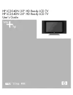
44
LC-20D42U
BLOCK DIAGRAM
Disclete
LPF
IC1301
I/O
M62320
<MUTE>
IC1404
CODEC
AK4683
IC8101
IXB870WJQZ
MAIN
I2C0
PCI/LOCAL BUS
SPDIF
Digital Audio
UART
SP
P2703(4p)
IC8454
EEPROM
BR24L64F
I2CEXT
HDMI 2
P9005
BUS Connecter
USB
IF
DTV_HDMI/I2S
DTV/SPDIF
SIF
IN1
IC2701
Digital AMP
TPA3101D
SP_L/SP_R
DTV_SPDIF
Tuner L/R
IN2
IN3
RX0
OUT1
OUT2
SDTOA
SDTIA2
SDTIA3
TX
HDMI 1
24-bit Digital
D3.3VD2.6V
Y
C
RGB 24 bit
CK,HD,VD,DE
RF IN
D IF
AGC
RGB
RGB_LR
OPTICAL
OUT
IC1507
TMDS
Selector
TMDS341A
TUN_I2C
IN4
IC8452
NOR FLASH
64Mb
CVBS
RX_x8
RX_x8
RGB
I2C_0
I2C_1
(100KHz) 3.3V
HD,VD
D3.3V
IC1401
Voice
multiplex
decoder
AN5832SA
AFT
RGBAudio
(Mini Plug)
INPUT
6
INPUT
4
INPUT
5
INPUT
6
RX1
SDTIB
EEPROM
RESET
To CPLD
A_OUT_SW
DTV_SPIDF
DTV_I2S
IC1104
DAC
M62332FP
I2C1
(100KHz) 5V
+5V
GAIN
EA[23:1
Tuner I2C
IF_AGC
D1.2V
Analog RGB
HD,VD
Digital IN
DVIDATA[23:0]
DVICLK
DVIHSYNC
DVIVSYNC
DVIDE
DS_AGCI_CTL
Digital Out
DVO DATA[23:0]
DVOCLK0
DVOCLK1
DVODE
DVOHSYNC
DVOVSYNC
DVODE
EDSAFE_CVBS_0
SD_L
SD_CVBS
FCLK
CVBS
SD_PB
SD_PR
SD_C
TMDS_SEL_D[2:0]
TMDS_SEL_CLK
HDMI_DATA[2:0]
HDMI_CLK
IC3304
RGB ADC
Mstar
3ch 10bit
ADC
(2mux/ch)
108MHz
1080i
85.5MHz
WXGA
HDMI_I2C
I2S_IN
I2S_OUT
X3301
14.318MHz
SD_Y
Y
Cb
Cr
+3.3V
+2.5V
IC1103
AMP
I2C_2 (400KHz) 3.3V
IC8451
EEPROM
B979WJ
EEPROM
D5V
D5V
A5V
D3.3V
+5V
D5V
D5V
A5V
D3.3V
UR6V
D3.3V
D3.3V
33
I2C_BSC
UART
CVBS
HDMI_L/R
HDMI Audio
INPUT
5
EEPROM
D5V
IC1504
1ShotMulti
VD
To M16
UART
P9301
Connector for
software
writing
I/O
EDSAFE_IF_P
EDSAFE_IF_N
EDSAFE_CVBS_1
1ch 12bit
ADC
(3mux/1ch)
108MHz
1080i
BU5V
Audio
Out
L/R
A9V
CVBS
CVBS
L/R
CVBS
S
IC501
AV SWITCH
MM3151XQ
Monitor
Out
TV
Main
Out
Video3
Video1
Video2
CVBS
S Video
INPUT
2
INPUT
3
INPUT
1
L/R
L/R
IC1407
SOUND DSP
TAS3108D
IC1405
Analog SW
D2.6
Port(OUT)
SC8401
USB
IC8401
Power
+UR6V
Component
CVBS/LR
YPbPr
IC1402
EEPROM
B991WJ
TU1101
Analog/Digital
Tuner
+5V
LR
CVBS/LR
+12V
+5V
MOBILE Audio_LR
IN5
30MHz
7MHz
7MHz
7MHz
7MHz
30MHz
30MHz
Summary of Contents for AQUOS LC-20D42U
Page 43: ... MEMO 43 LC 20D42U ...
Page 49: ...6 5 4 3 2 1 A B C D E F G H 49 LC 20D42U SCHEMATIC DIAGRAM ËLED Unit ...
Page 50: ...8 7 10 9 6 5 4 3 2 1 A B C D E F G H 50 LC 20D42U ËMAIN Unit 1 20 ...
Page 51: ...17 16 19 18 15 14 13 12 11 10 51 LC 20D42U ...
Page 52: ...8 7 10 9 6 5 4 3 2 1 A B C D E F G H 52 LC 20D42U ËMAIN Unit 2 20 ...
Page 53: ...17 16 19 18 15 14 13 12 11 10 53 LC 20D42U ...
Page 54: ...8 7 10 9 6 5 4 3 2 1 A B C D E F G H 54 LC 20D42U ËMAIN Unit 3 20 ...
Page 55: ...17 16 19 18 15 14 13 12 11 10 55 LC 20D42U ...
Page 56: ...8 7 10 9 6 5 4 3 2 1 A B C D E F G H 56 LC 20D42U ËMAIN Unit 4 20 ...
Page 57: ...17 16 19 18 15 14 13 12 11 10 57 LC 20D42U ...
Page 58: ...8 7 10 9 6 5 4 3 2 1 A B C D E F G H 58 LC 20D42U ËMAIN Unit 5 20 ...
Page 59: ...17 16 19 18 15 14 13 12 11 10 59 LC 20D42U ...
Page 60: ...8 7 10 9 6 5 4 3 2 1 A B C D E F G H 60 LC 20D42U ËMAIN Unit 6 20 ...
Page 61: ...17 16 19 18 15 14 13 12 11 10 61 LC 20D42U ...
Page 62: ...8 7 10 9 6 5 4 3 2 1 A B C D E F G H 62 LC 20D42U ËMAIN Unit 7 20 ...
Page 63: ...17 16 19 18 15 14 13 12 11 10 63 LC 20D42U ...
Page 64: ...8 7 10 9 6 5 4 3 2 1 A B C D E F G H 64 LC 20D42U ËMAIN Unit 8 20 ...
Page 65: ...17 16 19 18 15 14 13 12 11 10 65 LC 20D42U ...
Page 66: ...8 7 10 9 6 5 4 3 2 1 A B C D E F G H 66 LC 20D42U ËMAIN Unit 9 20 ...
Page 67: ...17 16 19 18 15 14 13 12 11 10 67 LC 20D42U ...
Page 68: ...8 7 10 9 6 5 4 3 2 1 A B C D E F G H 68 LC 20D42U ËMAIN Unit 10 20 ...
Page 69: ...17 16 19 18 15 14 13 12 11 10 69 LC 20D42U ...
Page 70: ...8 7 10 9 6 5 4 3 2 1 A B C D E F G H 70 LC 20D42U ËMAIN Unit 11 20 ...
Page 71: ...17 16 19 18 15 14 13 12 11 10 71 LC 20D42U ...
Page 72: ...8 7 10 9 6 5 4 3 2 1 A B C D E F G H 72 LC 20D42U ËMAIN Unit 12 20 ...
Page 73: ...17 16 19 18 15 14 13 12 11 10 73 LC 20D42U ...
Page 74: ...8 7 10 9 6 5 4 3 2 1 A B C D E F G H 74 LC 20D42U ËMAIN Unit 13 20 ...
Page 75: ...17 16 19 18 15 14 13 12 11 10 75 LC 20D42U ...
Page 76: ...8 7 10 9 6 5 4 3 2 1 A B C D E F G H 76 LC 20D42U ËMAIN Unit 14 20 ...
Page 77: ...17 16 19 18 15 14 13 12 11 10 77 LC 20D42U ...
Page 78: ...8 7 10 9 6 5 4 3 2 1 A B C D E F G H 78 LC 20D42U ËMAIN Unit 15 20 ...
Page 79: ...17 16 19 18 15 14 13 12 11 10 79 LC 20D42U ...
Page 80: ...8 7 10 9 6 5 4 3 2 1 A B C D E F G H 80 LC 20D42U ËMAIN Unit 16 20 ...
Page 81: ...17 16 19 18 15 14 13 12 11 10 81 LC 20D42U ...
Page 82: ...8 7 10 9 6 5 4 3 2 1 A B C D E F G H 82 LC 20D42U ËMAIN Unit 17 20 ...
Page 83: ...17 16 19 18 15 14 13 12 11 10 83 LC 20D42U ...
Page 84: ...8 7 10 9 6 5 4 3 2 1 A B C D E F G H 84 LC 20D42U ËMAIN Unit 18 20 ...
Page 85: ...17 16 19 18 15 14 13 12 11 10 85 LC 20D42U ...
Page 86: ...8 7 10 9 6 5 4 3 2 1 A B C D E F G H 86 LC 20D42U ËMAIN Unit 19 20 ...
Page 87: ...17 16 19 18 15 14 13 12 11 10 87 LC 20D42U ...
Page 88: ...8 7 10 9 6 5 4 3 2 1 A B C D E F G H 88 LC 20D42U ËMAIN Unit 20 20 ...
Page 89: ...17 16 19 18 15 14 13 12 11 10 89 LC 20D42U ...
Page 90: ...8 7 10 9 6 5 4 3 2 1 A B C D E F G H 90 LC 20D42U ËKEY Unit ...
Page 91: ...17 16 19 18 15 14 13 12 11 10 91 LC 20D42U ...
Page 93: ...17 16 19 18 15 14 13 12 11 10 93 LC 20D42U ...
Page 94: ...8 7 10 9 6 5 4 3 2 1 A B C D E F G H 94 LC 20D42U MAIN Unit Side A ...
Page 95: ...17 16 19 18 15 14 13 12 11 10 95 LC 20D42U ...
Page 96: ...8 7 10 9 6 5 4 3 2 1 A B C D E F G H 96 LC 20D42U MAIN Unit Chip Parts Side A ...
Page 97: ...17 16 19 18 15 14 13 12 11 10 97 LC 20D42U ...
Page 98: ...8 7 10 9 6 5 4 3 2 1 A B C D E F G H 98 LC 20D42U MAIN Unit Side B ...
Page 99: ...17 16 19 18 15 14 13 12 11 10 99 LC 20D42U ...
Page 100: ...8 7 10 9 6 5 4 3 2 1 A B C D E F G H 100 LC 20D42U MAIN Unit Chip Parts Side B ...
Page 101: ...17 16 19 18 15 14 13 12 11 10 101 LC 20D42U ...
Page 102: ...8 7 10 9 6 5 4 3 2 1 A B C D E F G H 102 LC 20D42U KEY Unit ...
Page 103: ...17 16 19 18 15 14 13 12 11 10 103 LC 20D42U ...
Page 119: ...119 LC 20D42U PACKING OF THE SET ...