background image

  33

Useful Features (Continued)

 View mode for HD programs

The following modes are available for HD programs.

S.STRETCH:

(Smart 

stretch)

Suitable for stretching 4:3 programs to fill the 

screen.

ZOOM:

Suitable for viewing wide-screen 2.35:1 

aspectratio programs in full screen.

STRETCH:

Suitable for viewing wide-screen 1.78:1 

aspectratio programs. 

When viewing 1.85:1 programs, stretch mode 

will still show very thin black bands at the top 

and bottom of the screen.

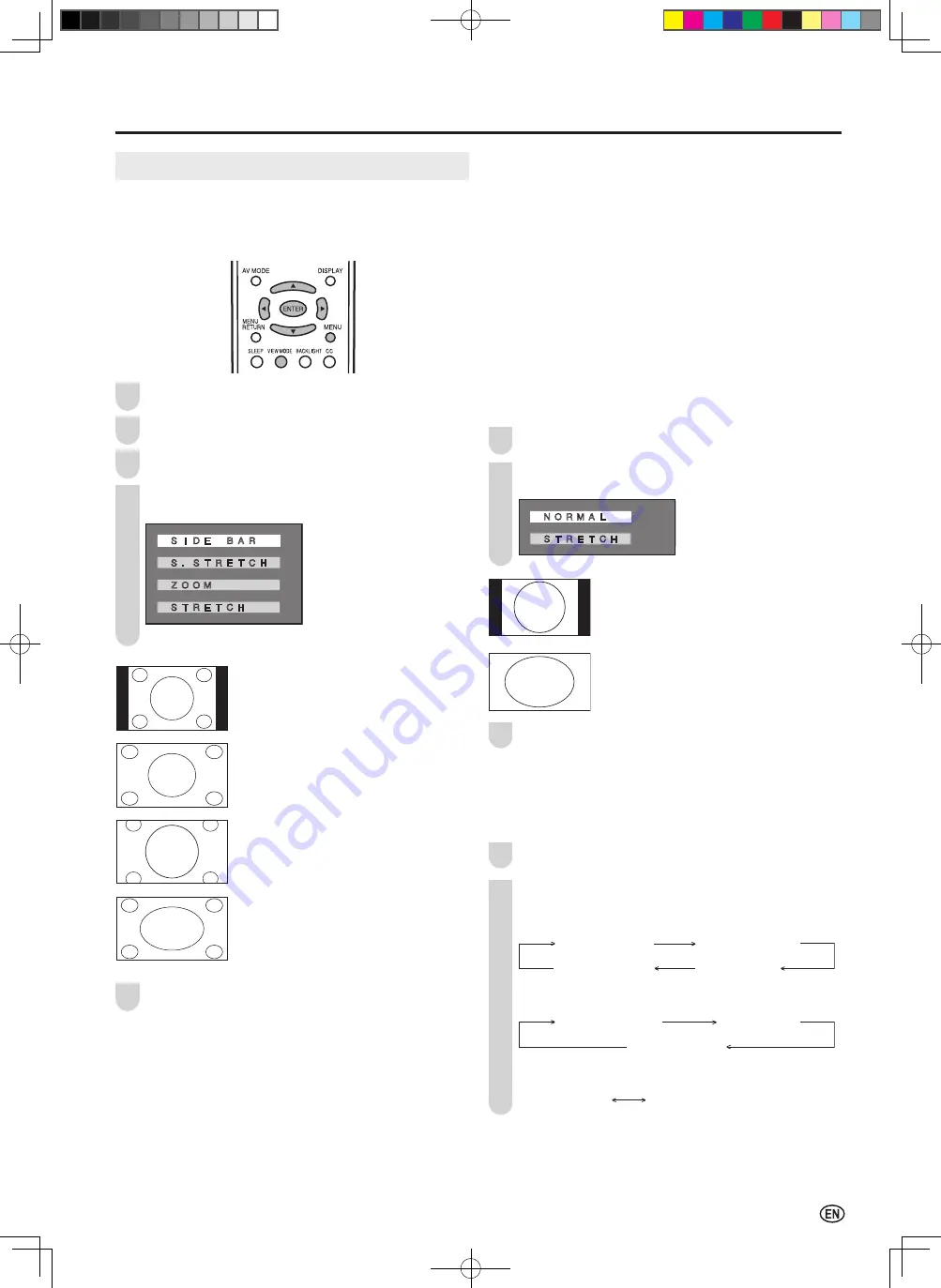
 View mode for PC mode

You can select the picture display size for PC mode from 

“NORMAL” or “STRETCH”.

Repeat steps 

1

 to 

3

 of 

View mode for 4:3 programs

.

Press 

'

/

"

 to select the desired setting, and press 

ENTER

.

� �

N O R M A L

� �

S T R E T C H

NORMAL:

Keep the original aspect ratio in a full screen 

display.

STRETCH:

An image fully fills the screen.

Press 

MENU 

to exit.

A

•  Connect the PC before making adjustments. (See page 

14

.)

•  Selectable screen size may vary with input signal type.

 Directly setting the VIEW MODE

Press 

VIEW MODE

.

Each time you press 

VIEW MODE

, the mode changes 

as shown below.
(4:3 programs)

VIEW MODE [SIDE BAR]

VIEW MODE [S.STRETCH]

VIEW MODE [STRETCH]

VIEW MODE [ZOOM]

(HD programs)

VIEW MODE [S.STRETCH]

VIEW MODE [STRETCH]

VIEW MODE [ZOOM]

(PC mode)

VIEW MODE [NORMAL]

VIEW MODE [STRETCH]

VIEW MODE

 View mode for 4:3 programs

You can select the picture display size for the playback 

image of the DVD player from the following four modes: 

“SIDE BAR”, “S.STRETCH”, “ZOOM” and “STRETCH”.

Press 

MENU

 to display the Menu screen.

Press 

\

/

|

 to select “OPTION”.

Press 

'

/

"

 to select “VIEW MODE”, and press 

ENTER

.

Press 

'

/

"

 to select the desired setting, and press 

ENTER

.

� �

S I D E

B A R

� �

S . S T R E T C H

� �

Z O O M

� �

S T R E T C H

SIDE BAR:

Suitable for viewing conventional 4:3

programs in their normal format.

S.STRETCH (Smart stretch):

Suitable for stretching 4:3 programs to

fill the screen.

ZOOM:

Suitable for viewing wide-screen

2.35:1 anamorphic DVDs in full screen.

STRETCH:

This mode is useful for 1.78:1 DVDs.

When viewing 1.85:1 DVDs, stretch

mode will still show very thin black

bands at the top and bottom of the

screen.

Press 

MENU 

to exit.

A

•  You can select a different VIEW MODE item for each input mode 

(INPUT1, INPUT2, INPUT3, INPUT4 and TV).

•  When 

CLOSED CAPTION” is set to 

CC1”, 

CC2”, 

T1” or 

T2”, 

ZOOM” cannot be set for 

VIEW MODE”.

1
2

3

4

1
2
3

5

1
2

LC-20D30U_E_book.indb   33

2005/12/15   11:27:25

Summary of Contents for Aquos LC 20D30U

Page 1: ...DE CRISTAL LÍQUIDO TELEVISOR DE CRISTAL LÍQUIDO OPERATION MANUAL MODE D EMPLOI MANUAL DE OPERACIÓN MANUAL DE OPERAÇÃO Products that have earned the ENERGY STAR are designed to protect the environment through superior energy efficiency Les produits agréés ENERGY STAR sont conçus pour protéger l environnement par un rendement énergétique supérieur SHARP ELECTRONICS CORPORATION Sharp Plaza Mahwah New ...

Page 2: ...64 100 10 31 64 266 15 381 21 15 64 539 5 43 64 144 9 17 32 242 2 5 8 66 5 4 1 32 102 3 61 64 100 2 9 64 54 17 17 32 445 2 9 57 64 251 17 9 64 435 15 7 16 392 1 45 64 43 10 31 64 266 16 5 16 414 LC 20D30U_E_Hyo1 4 indd 2 2005 12 16 11 10 34 ...

Page 3: ...SERVICEABLE PARTS INSIDE REFER SERVICING TO QUALIFIED SERVICE PERSONNEL The lightning flash with arrow head symbol within an equilateral triangle is intended to alert the user to the presence of uninsulated dangerous voltage within the product s enclosure that may be of sufficient magnitude to constitute a risk of electric shock to persons The exclamation point within a triangle is intended to alert...

Page 4: ...TION This equipment has been tested and found to comply with the limits for a Class B digital device pursuant to Part 15 of the FCC Rules These limits are designed to provide reasonable protection against harmful interference in a residential installation This equipment generates uses and can radiate radio frequency energy and if not installed and used in accordance with the instructions may cause...

Page 5: ... object can cause electric shock and or short internal parts For the same reason do not spill water or liquid on the product Servicing Do not attempt to service the product yourself Removing covers can expose you to high voltage and other dangerous conditions Request a qualified service person to perform servicing Repair If any of the following conditions occurs unplug the AC cord from the AC outle...

Page 6: ...acturer s instructions Use only the mounting hardware recommended by the manufacturer When relocating the product placed on a cart it must be moved with utmost care Sudden stops excessive force and uneven floor surface can cause the product to fall from the cart Ventilation The vents and other openings in the cabinet are designed for ventilation Do not cover or block these vents and openings since ...

Page 7: ...ECTION 810 21 GROUND CLAMPS POWER SERVICE GROUNDING ELECTRODE SYSTEM NEC ART 250 PART H ELECTRIC SERVICE EQUIPMENT NEC NATIONAL ELECTRICAL CODE GROUND CLAMP EXAMPLE OF ANTENNA GROUNDING AS PER NATIONAL ELECTRICAL CODE Lightning For added protection for this television equipment during a lightning storm or when it is left unattended and unused for a long period of time unplug it from the wall outle...

Page 8: ...NG 23 NOISE CLEAN 23 FILM MODE 24 QUICK SHOOT 24 AUDIO Adjustments 24 Useful Features 25 CH SETUP 25 SETUP 26 V CHIP Settings 27 CLOSED CAPTION 31 HDMI SETUP 32 VIEW MODE 33 AUDIO ONLY 34 BLUE SCREEN 34 SLEEP TIMER 35 WAKE UP TIMER 35 NO SIGNAL OFF 36 NO OPERATION OFF 36 PICTURE FLIP 36 Connecting a PC 37 Viewing an Image from a PC 37 Displaying an Image from a PC 37 INPUT SIGNAL for PC mode 38 FI...

Page 9: ... connection INPUT2 Terminal Terminal for S video connection INPUT3 OUTPUT Terminal Terminal for INPUT OUTPUT connection INPUT5 Terminal Terminal for PC connection INPUT4 Terminal HDMI Terminal for HDMI connection Connect the AC cord to the AC INPUT terminal of the LCD TV set and plug in the AC cord to the wall outlet See page 10 Turn on the main power See page 17 Press POWER on the upper side of t...

Page 10: ...from batteries can cause a rash If chemical leakage is found wipe it off with a cloth The batteries supplied with the LCD TV set may have a shorter operating time due to storage conditions If the remote control is not to be used for a long period of time remove the batteries from the remote control Preparation Engaging the lower claw with the remote control close the cover Using the Remote Control...

Page 11: ...hook to open the cover 300 75 ohm adapter not supplied 300 ohm twin lead 300 ohm twin lead 75 ohm coaxial cable IN OUT VHF antenna UHF antenna Combiner not supplied or or ANT Antenna terminal A Combination VHF UHF antenna B Separate VHF and or UHF antennas Antenna Cable commercially available F type connector should be finger tightened only When connecting the RF cable to the LCD TV set do not tigh...

Page 12: ...ovided by your cable TV company is explained below Please note An RF switch provided with two inputs A and B is required not supplied A position on the RF switch not supplied You can view all unscrambled channels by using the TV s channel keys B position on the RF switch not supplied You can view the scrambled channels via the converter descrambler by using the converter s channel keys CABLE TV CA...

Page 13: ...this operation manual provides a description based on operation using the remote control To change the vertical angle of the LCD TV set tilt the screen up to 2 5 degrees forward or 10 degrees backward Please adjust the angle so that the LCD TV set can be watched most comfortably Tilt the display by grabbing onto the carrying handle while securely holding down the stand with your other hand How to ...

Page 14: ...ormation that came with the system for instructions on how to use it to secure the LCD TV set ANT Antenna terminal AUDIO R AUDIO L VIDEO AUDIO ANALOG RGB HDMI INPUT3 OUTPUT INPUT5 PC IN INPUT4 AC INPUT terminal Y PB PR AUDIO L AUDIO R AUDIO L AUDIO R S VIDEO VIDEO INPUT1 COMPONENT INPUT2 How to Fix the Cables Secure cables and cords with the supplied cable clamp so that they do not get caught when...

Page 15: ...or system according to the country before using this product by following the table below The VIDEO INPUT mode is compatible with color systems worldwide and is automatically set A The 3 Dimensional Y C separation circuit works only in the following cases the color system is set to N358 in TV mode or Video mode the color system is set to AUTO N358 signal is received in Video mode The 3 Dimensional...

Page 16: ...l is received Outputting Video and Audio Video Output You can output video and audio signals from the LCD TV set through the INPUT3 OUTPUT terminals See page 26 When using INPUT3 OUTPUT as an output terminal select SETUP in the Menu and set INPUT3 SELECT to OUT A When using the S VIDEO input for INPUT2 COMPONENT input for INPUT1 HDMI input for INPUT4 or PC input for INPUT5 no video signal will be ...

Page 17: ...ss START EZ SETUP mode Press to select YES and press ENTER A If you want to stop the EZ SETUP process once it has started press MENU and it will be canceled If you want to set up again please refer to CH SETUP on page 25 Y E S N O C O N N E C T A N T E N N A O R C A B L E The tuner will automatically search for the broadcasting and cable TV channels The channel number will automatically increase w...

Page 18: ...e no channels with EDS signals set the clock manually using MANUAL CLOCK Repeat steps 1 to 4 of AUTO CLOCK Setting Press to select MANUAL and press ENTER S E T T I M E D I S P L A Y A U T O M A N U A L Press to select DST and press to select ON or OFF Press to select TIME and press to set the time and press ENTER 12 00AM 11 59AM 11 59PM 12 00PM Holding down changes the setting at a high speed S E ...

Page 19: ...00AM 4 00AM Autumn On the last Sunday in October DST finishes 1 00AM 2 00AM 1 00AM 2 00AM Turning On and Off the Main Power POWER POWER WAKE UP TIMER indicator Press POWER The POWER WAKE UP TIMER indicator instantly changes from red to green and the LCD TV set is turned on On screen display STEREO SAP MONO A The on screen display disappears in a few seconds To turn off the main power press POWER ag...

Page 20: ...tails on setting INPUT3 SELECT see page 26 INPUT4 Used for video equipment connected to the HDMI input terminal INPUT5 If you connect the PC to the PC IN terminals you can view the PC image on the LCD TV set Sound Volume To adjust the volume Press VOL to increase the sound volume The bar indicator shifts right VOLUME 50 Press VOL to decrease the sound volume The bar indicator shifts left 10 VOLUME...

Page 21: ... channel to the previously tuned channel Press FLASHBACK again to switch back to the currently tuned channel Selecting Menu Items The menus can be used to adjust the various settings of the LCD TV set Select the desired menu item by following the steps below See the next page for each Menu screen A The items displayed differ depending on the setting conditions The item selected is displayed in yel...

Page 22: ... 25 MTS 18 26 CLOCK 16 17 INPUT3 SELECT 26 V CHIP BLOCK 27 30 CLOSED CAPTION 31 COLOR SYSTEM 13 26 HDMI SETUP 32 PC SETUP 38 LANGUAGE 15 26 Page VIEW MODE 33 AUDIO ONLY 34 BLUE SCREEN 34 SLEEP TIMER 35 WAKE UP TIMER 35 NO SIGNAL OFF 36 NO OPERATION OFF 36 POWER MANAGEMENT for PC mode 39 PICTURE FLIP 36 AUDIO SETUP OPTION M E N U AUDIO PICTURE AUDIO SETUP OPTION T R E B L E ミ B A S S ミ B A L A N C ...

Page 23: ...below AV MODE STANDARD AV MODE DYNAMIC AV MODE DYNAMIC FIXED AV MODE MOVIE AV MODE GAME OPC Automatically adjusts the brightness of the screen Press MENU to display the Menu screen Press to select PICTURE Press to select OPC and press ENTER Press to select ON or OFF and press ENTER O N O F F 1 2 3 5 4 1 2 1 2 3 5 4 Press MENU to exit A When setting to ON the OPC indicator lights up green senses th...

Page 24: ...he OPC sensor which could affect its ability to sense surrounding light 3 PICTURE Adjustments You can adjust the picture to your preference with the following picture settings Press MENU to display the Menu screen Press to select PICTURE Press to select a specific adjustment item PICTURE AUDIO SETUP OPTION A V M O D E D Y N A M I C O P C O F F B A C K L I G H T BRIGHT C O N T R A S T 4 B R I G H T ...

Page 25: ... factory preset values perform the following procedure 1 Press to select RESET in the ADVANCED screen and press ENTER 2 Press to select YES and press ENTER Selected item button button RED Weaker red Stronger red GREEN Weaker green Stronger green BLUE Weaker blue Stronger blue When you select USER the following items are adjustable 2 1 3 4 A I P SETTING cannot be set when 480P 576P 720P or 1080I si...

Page 26: ... be set when 640 480 480P 576P 720P or 1080I signal is received from the HDMI terminal FILM MODE cannot be adjusted when the PC mode is selected as an input mode QUICK SHOOT Provides sharp pictures suitable for fast moving images such as a sports program Repeat steps 1 to 3 of COLOR TEMPERATURE on page 23 Press to select QUICK SHOOT and press ENTER O N O F F Press to select ON and press ENTER Pres...

Page 27: ... 2 through 125 STD HRC and IRC Useful Features Saving broadcast TV channels in the memory Repeat steps 1 to 3 of Setting the AIR CABLE Press to select CH SEARCH and press ENTER E Z S E T U P A I R C A B L E C A B L E 1 C H S E A R C H C H M E M O R Y Press ENTER The tuner will search through all available channels in your area and add them to the TV memory S T E R E O S A P M O N O 2 A To interrup...

Page 28: ...ing the LCD TV set For details about the following items refer to each indicated page CH SETUP Page 25 CLOCK Pages 16 and 17 V CHIP BLOCK Pages 27 to 30 CLOSED CAPTION Page 31 HDMI SETUP Page 32 PC SETUP Page 38 3 1 2 5 4 Selected item Factory setting Setting options MTS STEREO Stereo audio SAP Secondary audio program MONO Monophonic audio INPUT3 SELECT 1 IN INPUT3 OUTPUT terminals selected as inp...

Page 29: ...e based rating is blocked this will also automatically block the higher ratings R NC 17 and X A The MPAA rating is only age based TV parental guidelines Rating content based FV Fantasy Violence V Violence S Sexual Situation L Adult Language D Sexually Suggestive Dialog age based TV Y All children TV Y7 Direct to Older Children TV G General Audience X TV PG Parental Guidance Suggested TV 14 Parents...

Page 30: ...ay not be suitable for younger children under the age of 8 because it could contain controversial themes or issues 14e Over 14 Years Could contain themes where violence is one of the dominant elements of the storyline but it must be integral to the development of plot or character Language usage could be profane and nudity present within the context of the theme 18e Adults Intended for viewers 18 ...

Page 31: ...the 4 digit secret number by using Channel Select A When you input the secret number for the first time press ENTER to register Otherwise continue to step 5 Press to select the desired item and press ENTER M P A A T V G U I D E L I N E S C A N E N G L I S H R A T I N G S C A N F R E N C H R A T I N G S S T A T U S Press to select the desired item press to select BLOCK MPAA rating TV GUIDELINES G P ...

Page 32: ...ivating V CHIP BLOCK Setting STATUS You can activate V CHIP BLOCK after setting V CHIP Repeat steps 1 to 4 of Setting V CHIP on page 29 Press to select STATUS and press ENTER M P A A T V G U I D E L I N E S C A N E N G L I S H R A T I N G S C A N F R E N C H R A T I N G S S T A T U S Press to select ON and press ENTER O N O F F A If STATUS is set to OFF V CHIP BLOCK will not be activated Press MEN...

Page 33: ...r CH2 data T1 TEXT mode for CH1 data T2 TEXT mode for CH2 data Press MENU to exit Directly setting the CLOSED CAPTION Press CC to display the CC TEXT screen C C T E X T O F F Press CC to change the setting CC TEXT OFF CC TEXT T2 CC TEXT T1 CC TEXT CC1 CC TEXT CC2 A CC1 CLOSED CAPTION mode for CH1 data CC2 CLOSED CAPTION mode for CH2 data T1 TEXT mode for CH1 data T2 TEXT mode for CH2 data A If a b...

Page 34: ...e HDMI terminal with the DVI HDMI conversion cable it may not be possible to display the picture correctly HDMI SETUP can be adjusted only when INPUT4 HDMI is selected as an input mode See page 18 Refer to your external equipment operation manual for the signal type Selected item Setting options Description SIGNAL TYPE AUTO RGB YCbCr Select the signal type from an HDMI terminal Unless the image qu...

Page 35: ...ms VIEW MODE SIDE BAR VIEW MODE S STRETCH VIEW MODE STRETCH VIEW MODE ZOOM HD programs VIEW MODE S STRETCH VIEW MODE STRETCH VIEW MODE ZOOM PC mode VIEW MODE NORMAL VIEW MODE STRETCH VIEW MODE View mode for 4 3 programs You can select the picture display size for the playback image of the DVD player from the following four modes SIDE BAR S STRETCH ZOOM and STRETCH Press MENU to display the Menu sc...

Page 36: ...elect OPTION Press to select AUDIO ONLY and press ENTER Press to select ON and press ENTER O N O F F BLUE SCREEN This function automatically turns the screen blue if no broadcast signal or no input signal is received Press MENU to display the Menu screen Press to select OPTION Press to select BLUE SCREEN and press ENTER Press to select ON and press ENTER O N O F F Press MENU to exit A When receive...

Page 37: ...t Make sure to turn off the LCD TV set with the remote control The WAKE UP TIMER will not be activated if the LCD TV is turned off with POWER on the main unit A When you set WAKE UP TIMER the POWER WAKE UP TIMER indicator lights up orange while in the standby mode Be sure to adjust the clock with CLOCK in SETUP before setting SLEEP TIMER and WAKE UP TIMER You can output the picture and sound of th...

Page 38: ...interfered with by other broadcast or radio waves NO SIGNAL OFF may not work properly even when the broadcast is over NO OPERATION OFF When set to ENABLE the power will automatically shut down if there is no operation for 3 hours Repeat steps 1 and 2 of NO SIGNAL OFF Press to select NO OPERATION OFF and press ENTER Press to select ENABLE and press ENTER E N A B L E D I S A B L E 5 minutes before t...

Page 39: ... 3 B 8 GND Ground e HD 4 Not connected 9 5V r VD 5 CSYNC 0 GND Ground t SCL A Pin No 5 is not used for inputting the signal Pin No 9 is not connected with the supplied RGB cable Displaying an Image from a PC Ferrite core Connecting the RGB cable Connect the RGB cable making sure that it fits correctly into the terminal Then firmly secure the connectors by tightening the screws on both sides of the p...

Page 40: ...4 x 7 6 8 6 H z 8 x 6 6 H z 6 4 x 4 8 6 H z Press MENU to exit FINE SYNC Adjustments for PC mode You can adjust the PC image using the FINE SYNC menu Repeat steps 1 to 3 of INPUT SIGNAL for PC mode to display the PC SETUP screen Press to select FINE SYNC and press ENTER Press to select the specific adjustment item H P O S ミ V P O S ミ C L O C K ミ P H A S E ミ R E S E T 0 0 0 0 Press to adjust the ite...

Page 41: ...g time is displayed 5 minutes before the power is turned off Even if you start using the PC and the signal inputs again the LCD TV set stays off The LCD TV set turns on again by pressing POWER on the main unit or POWER on the remote control See page 17 OFF is factory preset value 3 1 2 4 5 Selected item Description ON If no signal inputs for 8 minutes the power shuts down OFF No power management P...

Page 42: ...nnected Bad reception could be the problem 9 10 Picture is not clear Make sure the antenna cable is properly connected Bad reception could be the problem 9 10 Picture is light or improperly tinted Check color adjustment Check COLOR SYSTEM setting 22 23 26 The picture is too dark Press the BACKLIGHT button or set the BACKLIGHT or BRIGHTNESS settings Check CONTRAST and BRIGHTNESS adjustment Fluoresc...

Page 43: ...cture is doubled or tripled Make sure the antenna is facing the right direction There may be reflected electric waves from mountains or buildings The picture is spotted There may be interference from automobiles trains high voltage lines neon lights etc There may be interference between the antenna cable and AC cord Try positioning them further apart There are stripes on the screen or colors fade I...

Page 44: ...tereo ø3 5 mm Antenna F Type Headphone Mini jack for stereo ø3 5 mm OSD language English Spanish French Power supply AC 110 240V 50 60Hz Power consumption 77 W 0 6 W standby AC 120V Weight Display only 15 5 lbs 7 0 kg Display with stand 17 5 lbs 7 9 kg Operating temperature 32 F to 104 F 0 C to 40 C Typical time for power output decrease of about one half assuming continuous use in a room with nor...

Page 45: ... manner and for the period of time described herein shall constitute complete fulfillment of all liabilities and responsibilities of Sharp to the purchaser with respect to the Product and shall constitute full satisfaction of all claims whether based on contract negligence strict liability or otherwise In no event shall Sharp be liable or in any way responsible for any damages or defects in the Pro...

Reviews: