background image

ENGLISH

17

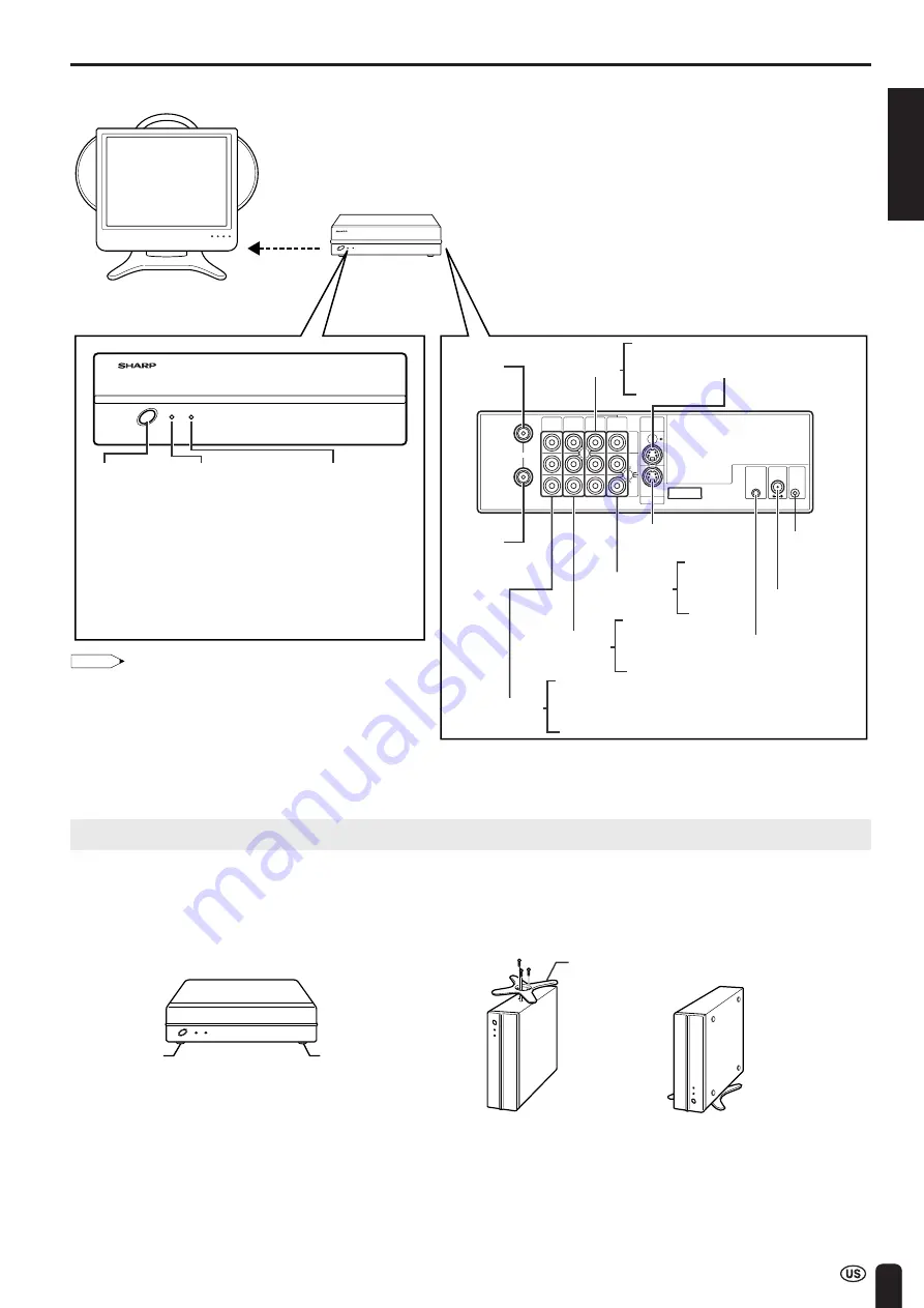
WIRELESS CENTER PART NAMES

SIGNAL LEVEL

MAIN

POWER

POWER

IN

OUT

AV-IN1

AV-IN1

AV-IN3

IR

OUT

POWER

INPUT

DC12V

FACTORY

SERVICE

S-VIDEO

MONITOR

OUT

MONITOR

OUT

VIDEO

AUDIO

L

AUDIO

R

AV-IN2

/OUT

ANT.

Transmission

SIGNAL LEVEL 
indicator
(Reception gain)

· Green: 

Communication 
in progress

· Red: 

Difficulty 
in transmission

· Not lit: 

Not communicating

POWER indicator

· Green: 

Operation in 
progress 
(when power is on)

· Red: Standby

MAIN 
POWER 
button

Front

Antenna 
input
terminal

Antenna 
output
terminal

Rear

VIDEO
AUDIO (L)
AUDIO (R)

AV-IN1 (S-VIDEO)

MONITOR
OUT

MONITOR OUT
(S-VIDEO)

Factory 
adjustment
terminal

POWER INPUT 
DC 12V

Video control 
terminal

VIDEO
AUDIO (L)
AUDIO (R)

AV-IN1

VIDEO
AUDIO (L)
AUDIO (R)

AV-IN3

VIDEO
AUDIO (L)
AUDIO (R)

AV-IN2
/OUT

Wireless Center

TV main unit

Wireless Center
stand

Rubber foot

Rubber foot

POWER Indicator

When the TV is turned off with the remote control, the
Wireless Center is switched to standby (POWER indicator
is lit red).  (There may be a time lag of about 5 to 6
seconds.)

Placing the Wireless Center Where You Want It

We recommend placing the Wireless Center in an area
where there are no obstructions to impede radio wave
transmission/reception.
(Do not place the Wireless Center in a box.)

Note:

The distance for which transmission is possible between the
main unit and Wireless Center is about 15 metres. However,
this distance may vary depending on the location or
conditions under which the Wireless Center is used.

If the main unit gets close to the Wireless Center, there may
be cases where noise appears on the screen. In this case,
keep the main unit away from the Wireless Center until the
noise decreases, or try to change the transmission channel
setting (page 

28

).

Setting up the Wireless Center

• The Wireless Center can be placed horizontally or upright.

When placing horizontally:

The side on which the rubber feet are attached is the
bottom.

When placing upright:

Fasten the stand to the bottom of the Wireless Center with
the screws provided.

* Failure to securely fasten the stand may cause the

Wireless Center to tip over during use.

Summary of Contents for Aquos LC 15L1U

Page 1: ...OPERAÇÃO ENGLISH FRANÇAIS ESPAÑOL PORTUGUÊS SHARP ELECTRONICS CORPORATION Sharp Plaza Mahwah New Jersey 07430 2135 SHARP CORPORATION Printed on 100 post consumer recycled paper Imprimé sur 100 de papier recyclé Impreso en 100 de papel reciclado de postconsumo Papel 100 Reciclado Cuidado do Meio Ambiente Printed in Japan Imprimé au Japon Impreso en Japón Impresso no Japão TINS B124WJZZ 04P02 ...

Page 2: ... symbol within an equilateral triangle is intended to alert the user to the presence of uninsulated dangerous voltage within the product s enclosure that may be of sufficient magnitude to constitute a risk of electric shock to persons The exclamation point within a triangle is intended to alert the user to the presence of important operating and maintenance servicing instructions in the literature...

Page 3: ...t harmful interference in a residential installation This equipment generates uses and can radiate radio frequency energy and if not installed and used in accordance with the operation manual may cause harmful interference to radio communications However there is no guarantee that interference will not occur in a particular installation If this equipment does cause harmful interference to radio or...

Page 4: ... Sound Volume 33 Changing Channels 34 SELECTING MENU ITEMS 35 ADJUSTMENTS 36 Adjusting SLEEP TIMER Settings 36 Adjusting BRIGHTNESS Settings 37 Adjusting PICTURE FLIP Settings 38 Adjusting PRESET Settings 39 Adjusting LANGUAGE Settings 40 Adjusting VIDEO ADJUST Settings 41 SETUP 43 Adjusting BLUE SCREEN Settings 45 Adjusting CLOSED CAPTION Settings 46 Adjusting V CHIP Settings 47 CONNECTION SYSTEM...

Page 5: ...he product through vents or openings High voltage flows in the product and inserting an object can cause electric shock and or short internal parts For the same reason do not spill water or liquid on the product Servicing Do not attempt to service the product yourself Removing covers can expose you to high voltage and other dangerous conditions Request a qualified service person to perform servici...

Page 6: ...e sure to follow the manufactur er s instructions Use only the mounting hardware recommended by the manu facturer When relocating the product placed on a cart it must be moved with utmost care Sudden stops excessive force and uneven floor surface can cause the product to fall from the cart Ventilation The vents and other openings in the cabinet are designed for ventilation Do not cover or block th...

Page 7: ...ide antenna system extreme care should be taken to keep from touching such power lines or circuits as contact with them might be fatal ANTENNA LEAD IN WIRE ANTENNA DISCHARGE UNIT NEC SECTION 810 20 GROUNDING CONDUCTORS NEC SECTION 810 21 GROUND CLAMPS POWER SERVICE GROUNDING ELECTRODE SYSTEM NEC ART 250 PART H ELECTRIC SERVICE EQUIPMENT NEC NATIONAL ELECTRICAL CODE GROUND CLAMP EXAMPLE OF ANTENNA ...

Page 8: ...ical reaction in order to generate electricity When the temperature outside is lower the chemical reaction becomes less vigorous and operating time becomes shorter How to Get the Most out of the Battery Turn off the power supply frequently when not in use in order to give the battery longer life The battery is consumed as time elapses even if the battery is not used To prevent consumption 1 If the...

Page 9: ...ed at an abnormal electric current or voltage An abnormal chemical reaction occurs inside the battery which may cause the battery to generate heat or smoke rupture or ignite Charge the battery in compliance with the specified charg ing conditions If the battery is charged without compliance to the charging conditions at temperatures greater than the specified temperature at voltages and electric c...

Page 10: ... house of a metal structure Using the product at locations near large scale metallic furniture Using the product in a crowd of people or close to buildings or obstacles etc Using the product at locations where magnetic fields electrostatic and interference occur due to devices such as Bluetooth wireless LANs or microwave ovens etc that utilize the same frequency band 2 4 GHz as the product Regardi...

Page 11: ...r SIGNAL LEVEL MAIN POWER POWER LIQUID CRYSTAL TELEVISION TÉLÉVISEUR ACL TELEVISOR CON PANTALLA DE CRISTAL LÍQUIDO TELEVISOR DE CRISTAL LÍQUIDO LC 15L1U OPERATION MANUAL MODE D EMPLOI MANUAL DE OPERACIÓN MANUAL DE OPERAÇÃO ENGLISH FRANÇAIS ESPAÑOL PORTUGUÊS Manuals Video controller 1 See page 12 Antenna cables 2 RRMCGA152WJSA LHLDZA216WJZZ UBAT1A011WJZZ GDAI A074WJSA TINS B124WJZZ QCNWGA033WJPZ QC...

Page 12: ...UM SUM 4 batteries 1 Open the battery cover Slide the cover while pressing the b part 2 Insert two AAA size UM SUM 4 batteries Position the positive and negative ends of the batteries as indicated in the compartment Caution Cautions regarding batteries Improper use of batteries can result in chemical leakage and or explosion Be sure to follow the instructions below Place batteries with their termi...

Page 13: ...on reception are more important than those for black white television reception For this reason a good quality outdoor antenna is strongly recommended The following is a brief explanation of the type of connections that are provided with the various antenna systems NOTICE F type connector should be finger tightened only When conecting the RF cable to the TV set do not tighten F type connector with...

Page 14: ...e TV company is explained below Please note An RF switch provided with two inputs A and B is required not supplied A position on the RF switch not supplied You can view all unscrambled channels by using the TV s channel keys B position on the RF switch not supplied You can view the scrambled channels via the converter descrambler by using the converter s channel keys CABLE TV CATV CONNECTION Note ...

Page 15: ...escribed in this manual CHARGE indicator POWER indicator Remote sensor window Table stand Detachable Left speaker Right speaker 15 SLEEP indicator 36 20 22 11 Main unit Top view Control section Main unit Front view CH VOL MENU TV VIDEO MAIN POWER VOL CH MAIN POWER TV VIDEO MENU 33 34 35 32 31 ...

Page 16: ...able stand release button Handle 1 2 CH CH ENTER POWER DISPLAY SLEEP PIC FLIP MUTE VOL BRIGHT TV VIDEO MENU FLASH BACK MTS Removing and Attaching the Table Stand 1 Lift the main unit straight up by holding the handle while depressing the table stand release button 2 Unfold the stand Securely unfold the stand until you hear a clicking sound Only use the stand after first unfolding until a clicking ...

Page 17: ...art of the back cover until the tab locks in place with a click Listening with Headphones Plug the headphone mini plug into the HEADPHONE jack located on the rear of the TV set Note Headphones are not included in the supplied accessories No sound is heard from the main unit speakers when a headphone mini plug is connected into the HEADPHONE jack On screen display Adjust the sound volume using VOL ...

Page 18: ...cator is lit red There may be a time lag of about 5 to 6 seconds Placing the Wireless Center Where You Want It We recommend placing the Wireless Center in an area where there are no obstructions to impede radio wave transmission reception Do not place the Wireless Center in a box Note The distance for which transmission is possible between the main unit and Wireless Center is about 15 metres Howev...

Page 19: ...djust the brightness of the screen 6 MUTE p 33 Mute the sound 7 VOL p 33 Set the volume 8 CH p 34 Select channel 9 MTS p 33 Select audio settings 10 PIC FLIP p 38 Set the orientation of the picture 11 a b c d Cursor control p 22 Select a desired item on the screen 12 TV VIDEO p 32 Select a Liquid Crystal Television input source 13 MENU p 35 Display the menu screen 14 FLASHBACK p 34 Return to the p...

Page 20: ...ry to the right The lever will return to its original position Move the battery to the right until the lever returns completely 5 Close the cover of the battery case Align the tabs of the cover with the corresponding grooves in the TV and snap into position When Removing With the lever pulled forward lift up on the battery while pushing to the left Always make sure to attach the terminal cover to ...

Page 21: ...ime The amount of remaining charge is only displayed when operating on battery power The remaining battery power indicator changes according to battery status temperature and conditions of use This indicator should be used as a reference for the amount of battery power remaining When Battery is not Charging Properly If the CHARGE indicator begins to flash extremely rapidly during charging this mea...

Page 22: ...tion during transmission of the video controller Using the AC Adapter Although the AC adapters may become warm during use this is not a malfunction Do not wrap or cover the AC adapters with a blanket or similar covering This can cause a malfunction or accident Do not attempt to disassemble or modify the AC adapters The insides of the AC adapter contain high voltage components that can result in th...

Page 23: ...NTER 4 Press a b to select ON or OFF When you select ON the TV set will automatically memorize the broadcasting channels 5 Press ENTER to access AUTO CLOCK mode 6 Press a b to select ON or OFF When you select ON the TV set will automatically search the time signals EDS signals provided by some TV stations to adjust the clock The AUTO CLOCK setting may take from several minutes to an hour depending...

Page 24: ...nals If EDS signals are received the channel number and time will be displayed and then the screen shown in step 8 appears 9 Once EZ SETUP is completed the lowest channel number memorized will be displayed Note Do not let the EZ SETUP screen remain unat tended for a long time If EZ SETUP does not memorize all the channels in your region please refer to pages 43 and 44 for more information on manua...

Page 25: ...R Note The CLOCK can be stopped completely by setting CLOCK to OFF SETTING THE CLOCK CLOCK AUTO CLOCK MANUAL CLOCK OFF SELECT ENTER EX I T RETURN ENTER MENU MENU SLEEP T IMER V IDEO ADJUST PRESET CLOSED CAPT ION V CHIP BLOCK SET UP SELECT ENTER EX I T ENTER MENU BLUE SCREEN OFF LANGUAGE SELECT EX I T ENTER RETURN SET UP CH SETT ING ENTER MENU CLOCK CH VOL POWER ENTER DISPLAY MUTE SLEEP PIC FLIP BR...

Page 26: ...TO CLOCK the time is acquired automatically when MAIN POWER is turned OFF This function will not work when EDS CH is not set Note CLOCK The AUTO CLOCK setting may take from several minutes to an hour depending on the number of channels to receive and signal status If there are no channels with EDS signals or the antenna signal is weak the AUTO CLOCK Setting may not operate In this case an EDS CH I...

Page 27: ...nued ENTER a b c d MENU Daylight Saving Time DST Adjustment The Daylight Saving Time changes as shown below Set the DST to ON to forward the clock by 1 hour To rewind the clock by 1 hour set the DST to OFF Spring On the first Sunday in April D S T starts Autumn On the last Sunday in October D S T finishes Advances 1 hour Rewinds 1 hour CH VOL POWER ENTER DISPLAY MUTE SLEEP PIC FLIP BRIGHT TV VIDEO...

Page 28: ...ally set Country TV broadcasting Factory setting of color system User setting system TV Video TV U S A Color NTSC NTSC N358 World Multi TV ch US ch US ch Auto System Not required or N A Canada Color NTSC NTSC N358 World Multi TV ch US ch US ch Auto System Not required or N A The World Multi Auto System is compatible with all color systems indicated below 1 N358 2 N443 3 PAL 4 PAL M 5 PAL N 6 SECAM...

Page 29: ... to NEAR However when reception is poor due to the presence of an interference source in close proximity change the settings for CHANNEL or DISTANCE to ensure normal reception ENTER a b c d MENU 1 Preparing for TRANSMISSION SETTING 1 Connect the antenna to the Wireless Center 2 Install the Wireless Center and TV receiver next to each other 3 Turn on the power for both the Wireless Center and TV re...

Page 30: ...me c d is pressed AUTO A B C ADJUSTING CHANNEL SETTING is displayed on the screen and the communication channel is set automatically MENU SLEEP T IMER V IDEO ADJUST PRESET CLOSED CAPT ION V CHIP BLOCK SET UP SELECT ENTER EX I T ENTER MENU BRIGHTNESS BRIGHT MTS AUTO POWER OFF RETURN STEREO OFF P ICTURE FL I P AV2 IN OUT BATTERY CHARGE NORMAL IN PRESET TRANSMISSION SETTING SELECT ENTER EX I T ENTER ...

Page 31: ...R MENU ENTER a b c d MENU 1 Press a b to select DISTANCE and then press ENTER 2 Press c d to select the desired distance and then press ENTER ADJUSTING DISTANCE SETTING is displayed on the screen and the communication distance is set automatically 3 Press MENU to return to the main screen Note Automatic channel selection is only made when the main unit is first switched on or when the function is ...

Page 32: ...WER button of the Wireless Center The POWER indicator of the Wireless Center turns green Standby To turn off the LCD TV Press POWER on the remote control The POWER indicator turns red To turn the LCD TV back on Press POWER again The POWER indicator turns green Control section of main unit CH VOL POWER ENTER DISPLAY MUTE SLEEP PIC FLIP BRIGHT TV VIDEO MENU FLASH BACK POWER On screen display 2 STERE...

Page 33: ...ideo terminal and normal video terminals are connected with cables the S video input terminal takes priority AV2 AV2 mode is used to adjust the preset settings and IN or OUT can be selected AV2 indication is not displayed when OUT is selected For details on setting AV2 IN OUT see page 39 AV3 Video equipment connected to the AV IN3 input terminals AV4 The AV4 input terminal is in the TV main unit T...

Page 34: ... The mute function is automatically turned off when any of the following buttons are pressed POWER VOL or MTS To select MTS Multichannel TV Sound 1 Press MTS to display the MTS screen 2 Press MTS to select the MTS settings STEREO stereo audio SAP secondary audio program MONO monophonic audio Note ON AIR appears when a STEREO or SAP broadcast is being aired BASIC OPERATION Continued CH VOL POWER EN...

Page 35: ...elected only when the receiving mode is set to CABLE in CH SETTING For details on setting the receiving mode see page 43 Press FLASHBACK to show the previous channel Tuning operation may take a few seconds to complete when using the remote control because of the wireless transmission speed This does not indicate a malfunction BASIC OPERATION Continued Channel Select CH FLASH BACK Changing channels...

Page 36: ...is operation manual are for explanation purposes and may vary slightly from the actual opera tions ENTER BRIGHT MENU SLEEP T IMER V IDEO ADJUST PRESET CLOSED CAPT ION V CHIP BLOCK SET UP SELECT ENTER EX I T ENTER MENU BRIGHTNESS BRIGHT MTS AUTO POWER OFF RETURN STEREO OFF P ICTURE FL I P AV2 IN OUT NORMAL IN PRESET TRANSMISSION SETTING P I CTURE 50 T INT COLOR BLACK LEVEL SHARPNESS SELECT ENTER EX...

Page 37: ...off when is displayed 5 Press MENU to return to the main screen Note When you set the SLEEP TIMER the SLEEP indicator LIGHTS UP RED After you set the SLEEP TIMER pressing MAIN POWER on the TV set or POWER on the remote control will cancel the SLEEP TIMER setting and the SLEEP indicator goes out 5 minutes before the SLEEP TIMER turns off the TV 5 REMAIN is displayed on the screen FOR 4 SECONDS The ...

Page 38: ...RIGHTNESS Settings You can adjust the brightness of the screen Directly setting the BRIGHTNESS 1 Press BRIGHT to display the BRIGHTNESS screen 2 Press BRIGHT to change the setting BRIGHT DARK NORMAL Note The BRIGHTNESS screen automatically disappears in 3 seconds BRIGHT maximum brightness NORMAL 60 brightness Suitable for viewing in a well lit area Saves energy DARK 10 brightness Sufficiently brig...

Page 39: ...RE FLIP 1 Press PIC FLIP to display the PICTURE FLIP screen 2 Press PIC FLIP to change the setting MIRROR ROTATE NORMAL UPSIDE DOWN Note The PICTURE FLIP screen automatically disappears in 3 seconds NORMAL normal image MIRROR mirror image ROTATE rotated image UPSIDE DOWN upside down image Setting the PICTURE FLIP on the MENU screen 1 Press MENU to display the MENU screen 2 Press a b to move the cu...

Page 40: ...E Rotated image To display rotated images for special uses UPSIDE DOWN Upside down image To display images upside down for special uses AV2 IN OUT IN AV IN2 terminals selected OUT Line Output is selected Output volume is fixed Speaker as input terminals output is available BATTERY CHARGE See page 28 In AV1 AV2 AV3 or AV4 mode MTS displayed in magenta cannot be selected ENTER a b c d MENU CH VOL PO...

Page 41: ...T ENTER MENU BLUE SCREEN OFF LANGUAGE SELECT EX I T ENTER RETURN SET UP CH SETT ING ENTER MENU CLOCK CH VOL POWER ENTER DISPLAY MUTE SLEEP PIC FLIP BRIGHT TV VIDEO MENU FLASH BACK ENTER MENU Adjusting LANGUAGE Settings The language for the On Screen Display can be ENGLISH SPANISH or FRENCH 1 Press MENU to display the MENU screen 2 Press a b to move the cursor to SET UP and press ENTER 3 Press a b ...

Page 42: ...P BLOCK SET UP SELECT ENTER EX I T ENTER MENU CH VOL POWER ENTER DISPLAY MUTE SLEEP PIC FLIP BRIGHT TV VIDEO MENU FLASH BACK ENTER a b c d MENU Adjusting VIDEO ADJUST Settings Video adjustments have different selection items depending on TV mode or AV mode signal from an external device See page 42 1 Press MENU to display the MENU screen 2 Press a b to move the cursor to VIDEO ADJUST and press ENT...

Page 43: ...Stronger blue GREEN Weaker green Stronger green AV mode Selected item Press c Press d PICTURE Decrease contrast Increase contrast TINT Toward purple Toward green COLOR Lower color intensity Higher color intensity BLACK LEVEL Less brightness More brightness SHARPNESS Soft picture Sharp picture RED BLUE Stronger red Stronger blue GREEN Weaker green Stronger green Note When BLUE SCREEN is set to ON V...

Page 44: ... is displayed in magenta and not available 4 Press c d to move the cursor to AIR CABLE and press ENTER 5 Press c d to move the cursor to the desired mode and press ENTER 6 Press MENU to return to the main screen Receivable channels of your TV set are AIR channels CABLE channels VHF 2 through 13 1 HRC and IRC UHF 14 through 69 2 through 125 STD HRC and IRC CH VOL POWER ENTER DISPLAY MUTE SLEEP PIC ...

Page 45: ...n press a b to move the cursor to SET UP and press ENTER 2 Press a b to move the cursor to CH SETTING and press ENTER 3 Press a b to move the cursor to CH SEARCH and press ENTER 4 Press d The tuner will search through all available channels in your area and add them to the TV memory To interrupt CH SEARCH press c CH SEARCH will stop at the current channel and will not add any higher channels 5 Pre...

Page 46: ...ngs BLUE SCREEN This function automatically turns the screen blue if no broadcast signal is received 1 Press MENU to display the MENU screen 2 Press a b to move the cursor to SET UP and press ENTER 3 Press a b to move the cursor to BLUE SCREEN and press ENTER 4 Press c d to select ON or OFF and press ENTER 5 Press MENU to return to the main screen Note When received signals are weak or interfered ...

Page 47: ...schedules and weather forecasts etc that is independent of the TV programs Setting the CLOSED CAPTION on the MENU screen 1 Press MENU to display the MENU screen 2 Press a b to move the cursor to CLOSED CAPTION and press ENTER 3 Press ENTER for the CLOSED CAPTION setting 4 Press c d to change the CLOSED CAPTION setting and press ENTER CC1 CC2 OFF T1 T2 Note CC1 CAPTION mode for CH1 data CC2 CAPTION...

Page 48: ...sted for complete control 1 MPAA RATING RATING Description G GENERAL AUDIENCES All ages admitted PG PARENTALGUIDANCE SUGGESTED Some material may not be suitable for children PG 13 PARENTS STRONGLY CAUTIONED Some material may be inappropriate for children under 13 R RESTRICTED Under 17 requires accompanying parent or adult guardian NC 17 NO ONE 17 AND UNDER ADMITTED X X is an older rating that is u...

Page 49: ...n be set TV PARENTAL GUIDELINES Example 1 When TV Y7 in the age based rating is set to BLOCK this will automatically block the higher ratings TV G TV PG TV 14 and TV MA In addition D L S V and FV in CONTENT are automatically blocked unless you manually set BLOCK CONTENT Example 2 When no item in the age based rating is blocked D in the content based rating will be automatically blocked Note Age ba...

Page 50: ...Continued SETTING V CHIP 1 MPAA RATING 1 Press MENU to display the MENU screen 2 Press a b to move the cursor to V CHIP BLOCK and press ENTER 3 INPUT SECRET NO will be displayed Input the 4 digit secret number by using Channel Select and press ENTER Note When you input the secret number for the first time press ENTER to register Otherwise continue to step 4 4 Press a b to move the cursor to MPAA a...

Page 51: ...S TV Y SELECT EX I T BLOCK CONTENT RETURN TV Y7 TV G TV PG TV 14 TV MA ENTER ENTER MENU Adjusting V CHIP Settings Continued 2 TV GUIDELINES Setting TV GUIDELINES 1 Repeat steps 1 to 3 of 1 MPAA RATING See page 49 2 Press a b to move the cursor to TV GUIDELINES and press ENTER 3 Press a b to move the cursor to TV Y7 and press ENTER 4 Press c d to select BLOCK and press ENTER If you set TV Y7 to BLO...

Page 52: ... EX I T RETURN L S V FV BLOCK CONTENT ENTER ENTER MENU Adjusting V CHIP Settings Continued Setting BLOCK CONTENT 1 Repeat steps 1 to 3 of 1 MPAA RATING See page 49 2 Press a b to move the cursor to TV GUIDELINES and press ENTER 3 Press a b to move the cursor to BLOCK CONTENT and press ENTER 4 Press a b to move the cursor to the desired item and press ENTER 5 Press c d to select BLOCK or unblock an...

Page 53: ... move the cursor to STATUS and press ENTER 3 Press c d to set STATUS to ON and press ENTER Note If STATUS is set to OFF V CHIP BLOCK will not be activated 4 Press MENU to return to the main screen 4 CANCELING THE V CHIP BLOCK SCREEN WHILE V CHIP BLOCK IS ACTIVATED 1 V CHIP HAS BEEN ACTIVATED appears if you watch a program with the same Program Rating data you configured Note V CHIP HAS BEEN ACTIVA...

Page 54: ...ed 2 Input the 4 digit secret number by using Channel Select the V CHIP select mode will be displayed Set V CHIP BLOCK again 6 CHANGING OR CLEARING THE SECRET NUMBER If you forget the secret number clear the secret number as follows 1 Repeat steps 1 to 2 of 1 MPAA RATING or 1 to 2 of 4 CANCELING THE V CHIP BLOCK SCREEN WHILE V CHIP BLOCK IS ACTIVATED then INPUT SECRET NO will be displayed 2 Press ...

Page 55: ...le another person is watching on a main TV in a living room Even if the power supply of the Wireless Center is turned off pictures and sound can be received by the main TV connected to the output terminals through and enjoyment is therefore possible even with a single television An antenna through output and a video 1 through output are provided at the LC 15L1U Wireless Center It is therefore poss...

Page 56: ...V IN1 AV IN1 AV IN3 IR OUT POWER INPUT DC12V FACTORY SERVICE S VIDEO MONITOR OUT MONITOR OUT VIDEO AUDIO L AUDIO R AV IN2 OUT ANT Audio Video cord Wireless Center Rear view To Audio Video output terminal VHF UHF antenna To antenna input terminal Antenna cable Antenna cable To antenna output terminal 1 1 2 3 2 3 Main unit LC 15L1U Operation in a separate room Equipped with AV IN4 system for playing...

Page 57: ...INPUT DC12V FACTORY SERVICE S VIDEO MONITOR OUT MONITOR OUT VIDEO AUDIO L AUDIO R AV IN2 OUT ANT AC wall outlet AC adapter AC cord AC wall outlet AC cord ANT S VIDEO AUDIO DIGITAL OPTICAL CO AXIAL OUT IN TV R L AUDIO VIDEO R L AUDIO VIDEO R L DVD player Decoder To Audio Video output terminal To AV IN1 S VIDEO terminal To AV IN2 OUT AV terminal To AV IN3 AV terminal To S VIDEO output terminal To Au...

Page 58: ...ems of video equipment can be operated using the video controller Cautions regarding installation of video controller The position of the infrared receiver of the remote control varies depending on the manufacturer or the type of the video cassette recorder Generally it is a small round shaped part close to the liquid crystal display portion Make sure that the transmitter of the video controller i...

Page 59: ...quipment is used for operating a VCR or a DVD CH VOL POWER ENTER DISPLAY MUTE SLEEP PIC FLIP BRIGHT TV VIDEO MENU FLASH BACK TV VIDEO Example Watching Played back Image from External Equipment When watching played back images from external equipment operations are carried out such as switching over the input source using the remote control for the TV main unit and playing back and selecting channe...

Page 60: ...then fitted into the cable clamps Note Game devices must always be connected to the input terminal of the main unit If a game device is connected to the Wireless Center you cannot enjoy the game comfortably because of a delay in the transmission of pictures and sound When connecting to both the VIDEO input and S VIDEO input terminals for AV IN4 priority is given to the S VIDEO input terminal When ...

Page 61: ... Yellow Red White Yellow The video controller is fixed so that the transmitter of the video controller faces the infrared receiver of the remote control for the video equipment Infrared receiver an example Video controller supplied When connecting to equipment having an S video terminal S video cord commercially available S video cord commercially available Audio Video cord commercially available ...

Page 62: ...t it will take about one second from pressing the picture record button on the remote control until actual picture recording starts When recording pictures or watching pictures on another device via the AV IN2 OUT terminal of the Wireless Center AV2 IN OUT is set to OUT If the television power supply is switched off using the remote control when the AV2 IN OUT is set to OUT the power supply of the...

Page 63: ...t The fluorescent lamp may have reached the end of service life Remote control does not work Check the batteries of the remote control Make sure the remote sensor window is not under strong lighting 41 65 56 60 33 33 16 12 12 41 42 37 41 65 11 11 The broadcasted EDS signal may be weak Check the antenna Carry out EZ SETUP SETTING THE CLOCK again If EDS signal is not sent set the clock using the MAN...

Page 64: ...the television product slightly Is the video controller connected Is the transmitter of the video controller facing the infrared receiver of the remote control for the VCR Does the VCR work when operating the remote control by directly facing the VCR If the VCR is still not working it can be considered that the battery of the remote control has run out 9 57 57 56 TROUBLESHOOTING Continued Pictures...

Page 65: ...stripes on the screen or colors fade Cautions regarding use in high and low temperature environments When the unit is used in a low temperature space e g room office the picture may leave trails or appear slightly delayed This is not a malfunction and the unit will recover when the temperature returns to normal Do not leave the unit in a hot or cold location Also do not leave the unit in a locatio...

Page 66: ...sh French Spanish Power supply TV main unit DC 15V Wireless center DC 12V TV main unit with stand 13 89 lbs 6 3 kg Weight without stand 11 02 lbs 5 0 kg Wireless Center 2 43 lbs 1 1 kg Accessories Wireless remote control 1 Remote control holder 1 Batteries 2 Battery 1 AC adapters 2 Wireless center 1 Wireless center stand 1 Cable clamps 2 Table stand 1 Video controller 1 Operation manual 1 Antenna ...

Page 67: ...OWER DISPLAY SLEEP PIC FLIP MUTE VOL BRIGHT TV VIDEO MENU FLASH BACK MTS 8 63 64 228 2 21 64 59 3 13 64 81 3 53 64 97 11 1 32 280 3 15 16 100 19 29 64 494 10 5 8 269 5 1 31 32 50 1 31 32 50 16 11 32 415 17 17 32 445 7 32 5 5 7 53 64 198 5 5 47 64 145 5 ...

Page 68: ...scribed herein or to extend the duration of any warranties beyond the time period described herein on behalf of Sharp The warranties described herein shall be the sole and exclusive warranties granted by Sharp and shall be the sole and exclusive remedy available to the purchaser Correction of defects in the manner and for the period of time described herein shall constitute complete fulfillment of...

Page 69: ...ing the warranty period warranty service may be obtained upon delivery of the Sharp product together with proof of purchase and a copy of this LIMITED WARRANTY statement to an Authorized Sharp Service Center or an Authorized Sharp Servicing Dealer In home warranty service may be provided at Sharp s discretion on any Sharp television with the screen size of 27 or larger and on any Sharp Over the Ra...

Reviews: