Sharp AE-X10CR Service Manual Download Page 10

10

AY-X10CR
AE-X10CR
AY-X10CR-N
AE-X10CR-N

20A

MODELS

EXCEPT FOR COOLING ONLY

5V

13V

CNE

16

17

50V

50V

1000pF

C119

0.022

µ

/

2W

/

2W

R110

68

/

10W

/

10W

R114

50V

.

01

µ

C18

C123

~

C128

C123

C124

C125

C126

C127

C128

/

10W

/

10W

/

10W

/

10W

/

10W

.

2K

2.2K

2.2K

.

2K

.

2K

/

10W

.

2K

R107

R104

R102

R105

R103

.

µ

PC106

PC922

C118

.

µ

C117

PC105

PC922

.

µ

C116

PC104

PC922

.

µ

C115

PC922

PC103

C114

.

µ

PC102

.

µ

C113

50V 1000pF


510

R94

D14

R90

.

µ

C47

C77

100

µ

IPM PWB

/

2W 180K

/

2W 180K

/

2W 180K

C129

.

µ

PC817

 x 

PC817

 x 

PC817

 x 

R76

R74

R75

.

3K

.

3K

.

3K

PC7

PC6

PC5

CN6

14.7KF

14.7KF

12.1KF

14.7KF

13

12

10

11

+ 7

330pF50V

330pF50V

330pF50V

100

R73

C50

C49

C48

R66

R64

R61

R68

R67

R78

R79

R69

R69,79:

R67,78:

R65,77:

R77

R65

R62

R63

/

2W 270K

R62,63:

C45

.

µ

50V

KIA339P

IC9

100Ω

R70

100

R71

100

R72

14

(WINTER KIT)

CN10

.

7KΩ

R6

R5

56K

R7

4.7KΩ

C13

.

µ

C16

100μF10V

C17

LED1

.

2KΩ

R3

10K

R15

R19

6.8K

1K R18

R14

.

2K

IC10

(for IPM)

(THERMISTOR)

CN7

C25

10

µ

16V

6.8KF

R23

CN13

(TO ACT(PFM))

50V

C41

0.1

µ

.

µ

.

µ

C108

.

µ

100

µ

C102

C110

C76

R82

-

+

10K

D8

100

µ

D5

RY1

D4

MRY1

D3

RY2

(for PIPE)

(for COMP)

(for OUTDOOR)

TH3

250V

NR1

SA1

FC4

FC5

D2

R8

.

7KF

C15

10V 220

µ

BCN11

CN101

10V

100

µ

C20

16V10

µ

C26

16V

10

µ

10

µ

C22

16V

C21

JP22

JP23

6.8KΩF

R38

6.8KΩF

R21

6.8KΩF

R20

10KΩ

R34

50V

.

µ

C19

390Ω

390Ω

390Ω

390Ω

390Ω

390Ω

R28

10KΩ

R36

C54

C51

C53

C52

1.5KΩ

R22

1.5KΩ

R25

1.5KΩ

R24

R35

10KΩ

.

µ

C82

.

µ

C81

50V

µ

C23

PST

993D

IC3

16MHz

OSC1

R10

.

8KF

.

0K

F 

R9

NR2

3A

250V

WPE3

-

WAY

Valve

2W

1.0K

R13

2W

1.0K

R11

2W

1.0KΩ

R12

0.1

µ

C12

250V 4700pF

CNR2

D1

10KΩ

R39

50V

1000pF

PC817X3

3.3K

R4

250V

WPE101

P(

+

YELLOW

YELLOW

BLACK

GRAY

DB1

FC2

ORANGE

WHITE

SACT32010E

WHITE

(CN13)

TO CONTROL PWB

11
22
33

44

C8

+

/

2W

180K

/

2W

180K

/

2W

180K

R116

R112

R113

C121

630V 

0.1

µ

5W

.

022

R101

ZD101

R108

26

CIN

CF0

25

24

23

FC1

C105

100

µ

D104

-

D103

CN102

BCN2

VP

UP

VVFB

VPI

VUFS

VUFB

VPI

PC107 PC817

 x 

47K

.

µ

C122

R109 820

.

7K

R115

FO

18

19

WP

UN

VWFB

VWFS

VPI

VVFS

C107

100

µ

C103

13

12

10

WN

VN

VPC

VNC

VNI

20

21

PC922

PC922

PC101

C106

.

µ

C109 0

.

1μF

D101

68

R111

C112

330

µ

C104

R57

.

01

µ

C40

IC4

D10

.

µ

C79

C78

330

µ

KIA7805API

IC7

7805

R91 750

IC5

12

R81

10K

C80

35V

C75

100

µ

D7

10

11

KIA7815API

7815

IC8

50V

.

µ

HZ24−2

PC817

 x 

.

5K

R60

PC817

 x 

PC3

390

R59

10K

R58

0.01

µ

C44

50V

0.1

µ

C43

R55 1M

.

3K

R56

KIA393P

R54

15.8KF

R53

34

.

8KF

IC6

R95

1K

50V 0

.

01

µ

R96

R97

.

53KF

PC817

 x 

PC12

0.01

µ

MA3810

250V

1A

WPE5

/

2W

470K

2W

.

3 R89

150pF 2KV

C70

C5

TB(TERMINAL BOARD)

BLUE

BROWN

RED

T1

T2

C31

275V 1

µ

275V


µ

275V


µ

250V

 4700pF

250V

 4700pF

250V

 4700pF

250V

 4700pF

+

C14

TH6

TH1

CN8

(THERMISTOR)

TH2

5V

NC

NC

NC

IPM PWB

NC

NC

470K

R88

13V

TR1

50V

KRC106M

-

AT

Q4

PC4

5V

18V

-

+

R52

/

2W270KF×2

R51

R50

.

8KF

R87

/

2W

R92

D13

C71

50V

C72

390

/

2W

GND

5V

6V

15V

5V

TP

WPE1

T4

GREEN/YELLOW

PTC

C33

C34

C4

C36

C35

C38

C37

 4700pF

250V

250V

 4700pF

C3

250V

 4700pF

 4700pF

250V

T6

T5

CT1

R2

R1

/

4W

510K

/

4W

C1

510K

L3

L4

C2

-

AC2

AC1

BROWN

L1

WHITE

BLUE

L1

L2

N1

ACT(PFM)

QM101(IPM)

100

µ

C101

.

µ

.

µ

D106

D105

C111

+

-

-

+

+

-

-

+

IPM

NC

NC

P61

Fan

Motor

RY2

CN4

T11

(WINTER KIT)

CN3

CNR1

RY1

IC1 TMP88CK48N

33

34

35

36

37

38

39

40

41

42

43

44

45

46

47

48

49

50

51

52

53

54

55

56

57

58

59

60

61

62

63

64

32

31

30

29

28

27

26

25

24

23

22

21

20

19

18

17

16

15

14

13

12

11

10

 9

 8

 7

 6

 5

 4

 3

 2

 1

P30

P31

P32

P33

P34

P35

P36

P37

P40

P41

P42

P43

P44

P45

P46

P47

P50

P51

P52

P53

P54

VAss

VARE

P60

P62

P63

P64

P65

P66

P67

Vdd

Vss

XOUT

XIN

RST

P22

P21

TEST

P20

P17

P16

P15

P14

P13

P12

P11

P10

P07

P06

P05

P04

P03

P02

P01

P00

P77

P76

P75

P74

P73

P72

P71

P70

5V

5V

5V

NC

NC

NC

NC

NC

NC

NC

KRC106M

-

AT

KRC106M

-

AT

KRC245M

-

AT

Q2

Q3

Q1

5V

5V

5V

PC1

JP1

T3

PC2

PC853H

R17

R16

10KΩ

10KΩ

1000pF

50V

C51

~

C54

R33

R31

R29

R32

R30

NC

NC

NC

NC

TN

ZD1

TV

TW

TU

RED

ORANGE

22

C120

11

15

14

15A

450V


.

µ

BLUE

MRY1

1000

µ

420V

44

33

22

11

CN12

(TO C8)

BLUE

N(−)

YELLOW

BLUE

BLUE

YELLOW

(RY2,D3,Q2)

MODELS

EXCEPT FOR COOLING ONLY

(RY2

CN4

CNR2)

47

100

R93

100

/

2W

/

2W

.

54KF

2.2K

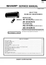
Figure L-3. Electronic Control Circuit Diagram for

OUTDOOR UNIT

Summary of Contents for AE-X10CR

Page 1: ...S 3 WIRING DIAGRAMS 5 ELECTRICAL PARTS 6 BLOCK DIAGRAM 6 MICROCOMPUTER CONTROL SYSTEM 8 FUNCTIONS 12 FUNCTION AND OPERATION OF PROTECTIVE PROCEDURES 18 BREAKDOWN DIAGNOSIS PROCEDURE 20 REFRIGERATION CYCLE 23 PERFORMANCE CURVES 24 DISASSEMBLING PROCEDURE 25 OPTION 32 REPLACEMENT PARTS LIST 33 REFRIGERANT PIPING INSTALLATION SERVICE MANUAL FOR AIR CONDITIONERS USING R 410A 39 TABLE OF CONTENTS INDOO...

Page 2: ...type Refrigerant system Condenser Corrugate Fin and Grooved tube type Control Capillary tube Refrigerant volume 770g R 410A De lce system Micro computer controled reversed systems Noise level High dB A 36 43 at cooling Med dB A 32 Low dB A 27 Fan system Drive Direct drive Air flow quantity High m3 min 9 8 27 7 at cooling Med m3 min 8 2 Low m3 min 6 1 Fan Cross flow fan Propeller fan Connections Re...

Page 3: ...E X10CR N EXTERNAL DIMENSIONS Figure E 1 INDOOR UNIT Figure E 2 OUTDOOR UNIT Length unit mm 815 278 198 1100 Remote controller 58 18 5 22 140 INVERTER AIR CONDITIONER 269 179 5 182 5 136 81 780 70 540 310 335 540 12 37 5 4 5 58 158 16 ...

Page 4: ...L THERMAL FUSE RECEIVER BOARD UNIT R P M SIGNAL FAN MOTOR CAPACITOR 430V 2 0µF FAN MOTOR LOUVER UPPER 1 3 TH1 5 CN1 BCN1 BCN3 BCN2 CN2 CN3 TH2 YELLOW ORANGE CN6 CN7 DISPLAY BOARD UNIT CN101 CN102 ROOM TEMP THERMISTOR PIPE TEMP THERMISTOR GREEN YELLOW TRANS1 SSR1 1 3 4 2 RED BLUE BLACK C1 LED INDICATION FOR SELF DIAGNOSIS 5 2 3 1 14 17 18 19 Short circuit of the outdoor thermistor Overheat of the c...

Page 5: ... 6sec 0 6sec 1 0sec 0 6sec 0 6sec CB565 1 2 3 4 10 NO LED indication pattern Mulfunction part or abnormal condition Normal Abnormal signal line Overheat of the compressor DC overcurrent of the power module QM101 Short circuit of the thermistor 7 8 6 NO LED indication pattern Mulfunction part or abnormal condition Open circuit of the thermistor AC overcurrent AC abnormal current BK 1 2 3 4 5 6 NR1 ...

Page 6: ...l louver motor lower Wireless remote control operation Audible operation confirmation Room temp thermistor Heat exchanger pipe thermistor Blower temperature fan speed model select Outdoor ratings Wireless preheat Indoor outdoor control signal I O Outdoor unit power supply on off control LED display Test run forced operation Auxiliary mode button ON OFF Self diagnostics fault diagnosis Unit unit wi...

Page 7: ...Power supply circuit CPU oscillator circuit DC overvoltage detection circuit Outdoor fan relay drive circuit 4 way valve relay drive circuit Power transistor module drive circuit Serial I O circuit CPU reset circuit Position detection circuit DC overcurrent detection circuit AC overcurrent detection circuit Compressor thermo circuit Heat exchanger pipe thermo circuit Outdoor temp thermo circuit Wi...

Page 8: ... R28 C20 R27 C19 R26 C18 JP34 2 8 9 15 C31 RY1 IC3 WPE1 3A 250V BLACK C4 C30 ZD1 JP99 R32 JP9 C8 JP28 D5 IC3 C6 R1 JP11 TRANS1 Q1 R3 R2 C3 CN8 1 1 2 3 3 8 IC7 C33 JP10 CN9 JP30 C13 R21 JP25 R38 2 3 3 D7 R63 C28 R57 3 4 1 2 JP14 TERMINAL BOARD TERMINAL BOARD JP13 BROWN IN OUT S RED N BLUE L1 SSR1 1 CN1 FAN M 5 JP12 CNR1 FAN M CN6 R23 R 6 6 R 6 7 R 6 2 R 6 1 R 6 0 R 5 9 D9 D8 1 D2 D4 D1 D3 C1 3 L GN...

Page 9: ...JP8 JP7 JP6 R30 380 R29 680 C19 C18 10µ 16V 16V 10µ 10K F R27 10K F R26 R21 R20 R19 C13 C12 C11 IC7 IC8 OSC1 F R O N T 1 2W R9 R8 C9 C10 1000p 50V 25V 0 1µ R5 RY1 R4 BZ1 BUSY 1 12V 2 5V 3 4 CLOCK 5 SERIAL OE 6 7 RESET GND 8 HOT KEEP PREHEAT WIRELESS 2 7K 50V 1000p 1000p 50V P37 P44 P46 P47 4 3 2 1 7 6 5 8 1 1K FUSE THERMAL SSR1 470 1 8K 16 9 10K 3 1 POWER SUPPLY SINGLE PHASE 2 1 JP10 33K R2 TRANS1...

Page 10: ...20 4 7K R115 FO 18 19 WP UN VWFB VWFS VPI VVFS 9 C107 100 µ F C103 13 12 10 8 WN VN VPC VNC VNI 20 21 7 1 2 7 PC922 PC922 PC101 C106 0 1 µ F C109 0 1μF D101 1 2 68 R111 C112 e 330 µ F C104 R57 0 01 µ F C40 IC4 D10 0 1 µ F C79 C78 330µF KIA7805API IC7 7805 R91 750 IC5 12 R81 10K C80 35V C75 100 µ F D7 10 11 KIA7815API 7815 IC8 50V 0 1 µ F HZ24 2 PC817 x 3 1 5K R60 PC817 x 3 PC3 390 R59 10K R58 0 01...

Page 11: ...T FROM FAN MOTOR FROM 4 WAY VALVE FROM IPM PWB U V W TO ACTIVE FILTER MODULE ACT FROM ELECTLYTIC CAPACITOR C8 FROM T6 TO MRY1 IN FROM CONTROL BOX FROM TERMINAL BOARD 1 TO IPM PWB CN101 OPTION FROM WINTER KIT FROM THERMISTOR COMP TEMP HEAT EXCHANGR TEMP OUTDOOR TEMP FROM HEAT SINK THERMISTOR FROM TERMINAL BOARD 2 FROM TERMINAL BOARD N ...

Page 12: ...s in the c zone when operation begins proportional integral control is not performed and the machine runs at frequency code 9 power until the i zone is reached When the h zone is reached the frequency changes to the frequency code determined by fuzzy calculation and after that integral control is performed 3 Dry After operation begins 2 minutes running at the h zone of the room temperature is stor...

Page 13: ...uency cord Fan speed Automatic 12 A B C A B C D E F G H HEATING 12 11 10 9 8 7 6 5 4 3 2 1 0 1 2 3 4 5 f e d Full power only j i h1 h2 g Dry Operating frequency code Fan speed Heating 24 C Heating 23 C Cooling 24 C Cooling 24 C Room temperature 2 C Cooling 25 C Cooling 26 C Dry Room temperature C When the cooling operation only can use winter kit 21 29 0 10 18 28 34 Outdoor temperature C Cooling 2...

Page 14: ...ssor to make heating start more quickly Operates when the indoor temperature sensor and external air sensor detect that the room temperature and outdoor temperature are low below 18 C and 5 C respectively Stops when the During Heating 1 11 Power ON start If a jumper wire is inserted into the place indicated JP99 on the indoor control board and the power plug is inserted cooling or heating will be ...

Page 15: ...ed Therefore for one hour since the operation is stopped the indoor temperature immediately before the operation is stopped is displayed After over one hour since it is stopped the unit displays the actual room temperature at that point 1 15 Error diagnostic display a Indoor unit 1 When an error is detected all relays are turned off At the same time the details of the error are displayed by flashi...

Page 16: ...will be stopped 4 Control for prevention of discharge overheating If the discharge temperature exceeds approximately 105 C during compressor operation the operating frequency is lowered by approximately 5 Hz After that the frequency is lowered by approximately 5 Hz once every 60 seconds When the discharge temperature goes below approximately 104 C the frequency is raised by approximately 5 Hz once...

Page 17: ...temperature of the heat sink decreases to 80 C 170 seconds after operation is stopped another try will be made Three retries are allowed On the fourth retry a complete stop request signal is sent to the indoor unit and the outdoor unit will remain stopped until reset is performed At this time the 3 minutes delay for control of the outdoor unit will not function therefore do not cancel by removing ...

Page 18: ... 58 C Stops the compressor if a current of approximately 23A or more flows in the power transistor module Lowers the operating frequency if the compressor AC current exceeds set value Show 2 2 1 AC peak control Stops the compressor if the current exceeds at 40Hz or less set value Lowers the operating frequency if the temperature of the compressor chamber thermistor TH1 rises above 105 C Stops the ...

Page 19: ... unit does not receive a serial signal from the indoor unit for 30 seconds When power factor module error input is detected When abnormalities occur to a position detected signal Stops the compressor if the circuit of the heat sink thermistor Stops the compressor if the temperature of the power module is IPM is exceeds 90 C Also stops the compressor if the heat sink thermistor shorts During compre...

Page 20: ...n errot of the compressor 1 Has not if escaped from the compressor CN6 2 Is the power supplied of 15V and 6V supplied to the IPM PWB 1 Replace the heatsink thermistor Open circuit of the heatsink thermistor 1 Are the connectors of the heatsink thermistor in outdoor unit well attached 2 Measure the resistance of thermistor TH6 on the heatsink See Figure 3 Overheat of the comp ressor error protector...

Page 21: ...agnosis Solution Condition of indoor and outdoor unit Serial short Serial open 1 Check the wiring between units 1 Check the wiring between units 1 Check the wiring between units 2 Check the fuse in the outdoor unit 3 Indoor control board 4 Outdoor control board 1 Rewire 1 Rewire Indoor fan out of order 1 Is the fan motor locked 2 Is the wiring connector firmly fitted 3 Is the rotation pulse signal...

Page 22: ...Orange No 5 to 6 Green Microcomputer terminal Input signal To Outdoor control board Adaptor R22 GND R16 Pin No 27 Pin No 28 0 1 0 Low input 1 High input K Heat exchange thermistor TH2 orange 25 C resistance 15 K Room temperature thermistor TH1 yellow 25 C resistance 10 K 25 C resistance 45 K Resistance Resistance 0 C resistance 14 5 K 25 C resistance 4 431 K Figure 2 Temperature properties of heat...

Page 23: ...l Indoor side Standard conditions Dry bulb Temp C Relative Humidity 20 Heating Outdoor side Dry bulb Temp C Relative Humidity 7 87 27 Cooling 47 35 40 Temperature at each part and pressure in 3 way valve Operation mode Cool Max Heat Max Cool Heat 1 2 3 4 3 way valve pressure MPaG 0 85 2 43 1 10 2 00 82 C 45 C 11 C 8 C 80 78 C 1 C 38 C 6 C more than 80 65 C 40 C 15 C 12 C 40 settle 59 C 2 C 32 C 4 ...

Page 24: ...ir temp Cooling 27 C Heating 20 C Figure P 1 At Cooling Figure P 2 At Heating 25 30 35 40 2 4 2 6 2 8 3 0 3 2 12 14 16 700 800 900 1000 Running frequency 63Hz Cooling capacity kW Outside air temp C Input W Outlet air temp C 5 0 5 7 10 2 5 3 0 3 5 4 0 30 35 40 45 800 900 1000 1100 Running frequency 79Hz Heating capacity kW Outside air temp C Input W Outlet air temp C ...

Page 25: ...w fixing the cord clamp Note During reassembly install the holder after installing the front panel This will make it easier to assemble the front panel 4 Close the open panel Pushing the nail of the front panel 5 Pull the front panel up 6 Remove the unit to unit wiring from the terminal board 7 Remove a screw fixing the control box cover and remove it 8 Remove a screw fixing the ground wire Note D...

Page 26: ...connectors 11 Remove the thermistor holder from the evaporator 12 Remove the display from the drain pan 13 Remove the screw fixing the pipe holder 14 Remove 3 screws fixing the control box and remove the control box 15 Remove a screw fixing the drain pan 16 Pull drain pan toward you CN1 CN6 CN3 CN2 ...

Page 27: ...rom the cabinet 20 Remove 2 screws fixing the motor cover and pull up the fan 21 Loose a screw fixing fan Cautionary points for assembling the fan a When inserting the motor shaft into the metal fan boss take care to prevent injuring the inner surface of the metal fan boss b Before fastening the motor shaft and fan insert the motor shaft into contact with the bottom of the metal fan boss Fan motor...

Page 28: ...nt panel along the guide from the center of the front panel 2 After the left half is inseted completely press the display cover and snap in the 3 hooks on the right How to remove the control box 2 Remove the screw fixing the terminal board 1 2 1 Remove the photo detector unit Press and spread the upper hook and the photo detector unit will be ready for removal 3 Remove a screw fixing the cord hold...

Page 29: ... pan During installation turn the drain hose to the state of the engagement position After reinstallation verify that it is securely fastened How to remove the horizontal louver Slightly pull down the hinge area defelect thge louver and unhook it from the hinge Remove the shaft from each of the left and right sides Drain pan Drain Hose Groove Projection To disconned To reconnect ...

Page 30: ...e side cover Right side view Left side view Right side view Left side view Front view 2 Loose the unit to unit cord 3 Loose a screw fixing the cord clamp 4 Loose 4 screws fixing the top panel 5 Loose 6 screws fixing the front panel 6 Cut 4 nylon bands 7 Disconnect following connectors and each wire Choke coil two terminal Fan motor Thermistor Reverse valve ...

Page 31: ...the terminal cover of compressor 9 Remove 3 terminals of compressor 10 Loose 4 screws fixing the control box 11 Take out the control box DISASSEMBLING PROCEDURE OF THE FAN 1 Loose the fan nut and fan can take out 2 Fan motor is secured by 4 screws Loose ...

Page 32: ... air filter up slightly to unhook them 2 CHECK THE AIR PURIFYING FILTERS 1 Take of the old air purifying filters from the air filters Snap out in the arrow marked direction 2 Set the new air purifying filters with filter stopperts located on the air filters 3 REINSTALL THE AIR FILTERS 1 Reinstall the air filters in the original positions 2 Close the front panel 3 Push the center part of the panel ...

Page 33: ...Z Drain cover 1 AG 1 33 TLABCB612JBRZ Wiring diagram 1 AE 1 34 QW VZD893JBZZ Lead wire Lower 1 AG 1 35 LHLD A303JBFA Tube cover 1 AD 1 36 PSEL C125JBEZ Panel insulator 1 AF 1 37 HDEC B134JBEZ Display panel 1 AP 1 38 PFPFPB967JBEZ Sidecover insulator 1 AC 1 39 PSEL C055JBEZ Evaporator seal 1 AC 1 40 PSHE A126JBE0 Evaporator seal 1 AG 1 41 LSPR A007JBE0 Seet spring 2 AD 1 42 PSEL C136JBEZ Insulator ...

Page 34: ...1 AL 3 4 PVLV 0341JBE0 Flare union 1 4 1 AG 3 5 PVLV 0342JBE0 Flare union 3 8 1 AH 3 6 DEVA A128JBKZ Evaporator sub assembly 1 BT ACCESSORY PARTS 4 1 CRMC A528JBEZ Remote control 1 BB 4 2 UBATUA027JBE0 Battery pack 1 AE 4 3 LHLD A477JBFA Cord holder for covering the terminal board of indoor unit 1 AE 4 4 XTTSD40P16000 Tapping screw for fixing the cord holder 1 AA 4 5 LX NZA207JBEZ Special nut for ...

Page 35: ...1 41 1 18 1 5 1 4 1 29 1 3 1 26 4 7 2 11 1 22 1 1 1 12 1 32 1 2 2 1 3 1 2 4 2 5 3 2 3 5 3 3 3 4 2 1 5 1 1 7 2 13 2 2 2 18 2 14 1 21 4 3 4 4 2 6 2 7 1 16 1 30 1 19 1 19 1 13 1 20 1 14 1 13 1 11 1 17 1 10 1 6 1 27 6 1 6 2 1 24 1 25 1 31 1 37 1 28 1 33 1 36 1 25 2 3 2 19 2 12 2 10 4 9 4 11 4 8 4 12 4 5 4 10 4 43 2 9 1 15 1 34 1 8 1 8 2 8 1 9 1 9 INDOOR UNIT ...

Page 36: ...LEAD 1 AE 1 34 QW VZD959JBZZ Lead wire DB1 AFIN 1 AG 1 35 QW VZE194JBZZ Lead wire AFOUT C8 1 AG 1 36 QW VZE195JBZZ Lead wire AFOUT C8 1 AG 1 37 QW VZE196JBZZ Lead wire C8 IPM PWB 1 AL 1 38 QW VZE190JBZZ Lead wire MRY1 T6 1 AE 1 39 QW VZE191JBZZ Lead wire T5 DB1 AC2 1 AF 1 40 QW VZE192JBZZ Lead wire MRY1 DB1AC1 1 AF 1 41 QW VZE199JBZZ Lead wire ACT CN13 1 AF 1 42 QW IZA035JBZZ Lead wire Compressor ...

Page 37: ...JBEZ Compressor cover 1 AQ 3 13 PSPF A841JBEZ Compressor cover 1 AF 3 14 PSPF A850JBEZ Compressor cover 1 AG 3 15 PSPF A851JBEZ Compressor cover 1 AK 3 16 PSPF A852JBEZ Bulkhead cover 1 AG 3 17 PSEN A044JBKZ Flare nut ass y 1 AG 3 18 PSEN A045JBKZ Flare nut ass y 1 AK 3 19 PGUM A135JBEZ Compressor sheet 1 AG 3 20 PSPF A839JBEZ Compressor cover 1 AG 3 21 PMUF A060JBEZ Muffler 1 AP 3 21 PMUF A061JBE...

Page 38: ... 18 3 6 3 5 3 4 3 7 3 17 3 11 1 3 4 12 1 20 2 29 4 1 4 6 1 8 1 49 1 21 4 6 1 16 1 4 4 16 1 23 1 12 4 1 4 1 4 9 4 9 1 10 1 9 4 9 1 19 4 7 1 11 1 51 1 50 4 11 3 12 2 11 2 12 4 13 4 1 4 1 4 2 4 2 2 7 4 1 4 1 4 13 4 1 4 5 1 14 3 2 3 1 3 2 2 16 4 1 1 15 4 14 2 28 4 1 4 1 4 4 2 2 1 1 2 18 4 10 2 1 4 13 2 5 4 1 2 8 2 32 2 21 2 22 1 14 4 3 2 37 4 14 2 15 2 35 2 34 2 24 2 26 2 27 4 13 4 13 4 16 4 8 1 53 1 ...

Page 39: ...42 2 3 Storage of Piping Materials 44 3 Installation Removal and Services 44 3 1 Tools for R410A 44 3 2 New Installation Work When Using New Refrigerant Piping 46 3 3 Removal When Using New Refrigerant Piping 48 3 4 Replacing the UNit Never Use the Existing Refrigerant Piping 48 3 5 Retrofitting 48 3 6 Refrigerant Recharging at Servicing 49 TABLE OF CONTENTS Refrigerant Piping Installation Servici...

Page 40: ... 50 R22 100 72 6 86 5 51 4 40 8 1 56 0 94 64 0 44 4 Nonflammable Nonflammable 0 0 055 1730 1700 Molecular weight Boiling point C Vapor pressure 25 C MPa Saturated vapor density 25 C kg m2 Inflammability Ozone depletion potential ODP Global warming potential GWP Source List of Thermophysical Properties complied by the Japan Sociery of Refrigeration and Air Conditioning NIST REFPROP V5 10 etc b Comp...

Page 41: ... space heater etc a poisonous gas may occur 5 When an air conditioning system charged with a large volume of refrigerant e g multi type air conditioner is installed in a small room it is necessary to exercise care so that even when refrigerant leaks its concentration does not exceed the marginal level If teh refrigerant gas leakage occurs and its concentration exceeds the marginal level an oxygen ...

Page 42: ...r a flare tool for R410A or conventional flare tool Flare processing dimensions differ according to the type of flare tool Be careful When using a conventional flare tool be sure to secure dimension A by using a gage for size adjustment Table 4 Dimensions related to Flare Processing for R410A Norminal diameter Norminal diameter mm A mm Conventional flare tool Clutch type Wing nut type 1 5 2 0 1 5 ...

Page 43: ...a torque wrench The tightening torque for R410A is same as that for conventional R22 Incidentally when the torque is wekd the gas leakage may occur When it is strong the flare nut may crack and may be made nonremovable When choosing the tightening torque comply with values designated by manufacturers Table 9 shows reference values Note When applying oil to the flare surface be sure to use oil desi...

Page 44: ...eat it with exceeding care and adopt a means for identification to prevent improper usage by making it easily discriminable from other piping materials 3 Precautions before Installation Observe the following precautions when performing the piping connection at the site a Keep any open ends of pipes be sealed with a cap etc until connected with the equipment b Exercise great care when performing pi...

Page 45: ...ports one for R22 7 16 UNF 20 threads per inch and the other for R410A 1 2 UNF 20 threads per inch it can also be used for charging the conventional refrigerant Two types of electronic balance for refrigerant charging are available one for 10 kg cylinder and the other for 20 kg cylinder Electronic balance for 10 kg cylinder precision 2g Electronic balance for 20 kg cylinder precision 5g Refrigeran...

Page 46: ...del Gauge manifold Tools for R410A Applicable to R22 model Charge hose Electronic balance for refrigerant charging Torque wrench norminal diameter 1 2 5 8 Flare tool clutch type Gauge for projection adjustment Vacuum pump adapter Refrigerant cylinder Charge port and packing for refrigerant cylinder Gas leakage detector Used when conventional flare tool clutch type is used Note For inquiry contact ...

Page 47: ...rigerant 2 5 e When the designated amount of refrigrant could not be charged make additional charging bit by bit by cooling operation for the amount of each addition follow the instruction manual prepared by the equipment manufacturer If the first additional charging was not enough make the second additional charging after about one miunte in the same manner as the first additional charging CAUTIO...

Page 48: ...nitÅfs control valves and service port with the specified torque Tighten the capped flare nuts at the indoor outdoor units connecting part with the specified torque Remove the indoor outdoor units CAUTION When storing the indoor unit piping in its original position be careful not to break the piping 2 Installing the Unit a Proceed with the installation following the steps described in 3 2 New Inst...

Page 49: ... At this time keep the control valves in the fully opened position 3 Place the handle Lo in the fully opened position and turn ON the vacuum pumpÅfs power source For the evacuating time refer to the equipment manufacturer s manual 4 When the compound gauge s pointer has indicated 0 1 MPa 76 cmHg place the handle Lo in the fully closed position and turn OFF the vacuum pump s power source Keep this ...

Page 50: ...50 AY X10CR AE X10CR AY X10CR N AE X10CR N ...

Page 51: ...51 AY X10CR AE X10CR AY X10CR N AE X10CR N ...

Page 52: ...52 AY X10CR AE X10CR AY X10CR N AE X10CR N 02 SHARP CORP 8U0 10E Printed in Germany ...

Reviews: