background image

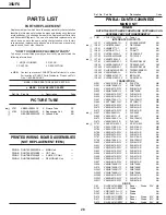
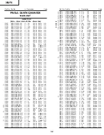
PRINTED WIRING BOARD ASSEMBLIES

PARTS LIST

PARTS REPLACEMENT

Replacement parts which have these special safety characteristics
identified in this manual; electrical components having such features
are identified by 

å

 and shaded areas in the Replacement Parts Lists

and Schematic Diagrams. The use of a substitute replacement part
which dose no have the same safety characteristic as the factory
recommended replacement parts shown in this service manual may
create shock, fire or other hazards.

"HOW TO ORDER REPLACEMENT PARTS"

To have your order filled promptly and correctly, please furnish the
following informations.

1. MODEL NUMBER

2. REF. NO.

3. PART NO.

4. DESCRIPTION

in USA:

Contact your nearest SHARP Parts Distributor to order.
For location of SHARP Parts Distributor, Please call Toll-
Free; 1-800-BE-SHARP

«

  MARK:  SPARE PARTS-DELIVERY SECTION

p


MARK:   X-RAY RELATED PARTS

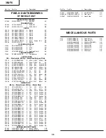
PICTURE TUBE

(NOT REPLACEMENT ITEM)

MAIN UNIT

PWB-A: DUNTKC290WED5

TUNER

NOTE:THE PARTS HERE SHOWN ARE SUPPLIED AS AN

ASSEMBLY BUT NOT INDEPENDETLY

Ref. No. Part No. 

«

 Description Code

p

 V101 VB81E X Picture Tube CY

L703

RCILGA048WJZZ

X

Degaussing Coil

AR

 QEARCA009WJZZ X Ground-Part AD

PWB-A DUNTKC290WED5 — MAIN Unit —
PWB-B DUNTKA527WEE2 — CRT Unit —
PWB-C DUNTKB573WEV0 — 3-LINE Y/C Unit —
PWB-H DUNTKB569WEV0 — DF MODULE Unit —

INTEGRATED CIRCUITS

Ref. No. Part No. 

«

 Description Code

TU51

VTUVT1T5UF202

X

Tuner

AS

IC101

VHIPQ050ES1-1+

X

AD

p

IC201

VHITB1253AN-1

X

AS

IC361

VHIAN5277//-1

X

AK

IC501

VHI-1

X

AG

IC701

VHITEA1533A-1

X

AG

IC702

RH-FXA003WJZZ

X

AC

p

IC703

VH+-F

X

AF

IC751

VHIPQ09RDA1-1

X

AF

IC900

VHICXA2089Q-2Y

X

AM

IC1403

VHIPQ05RDA1-1

X

AF

IC2001

RH-IXA418WJZZQ

X

AQ

IC2040

VHIKIA7045A-1+

X

AC

IC2101

VHIBR24L16F-1Y

X

AE

IC3001

VHICXA2194Q-1Y

X

AR

Q201

VS2SC2735//1EY

X

AB

Q361

VS2SB709AR/-1Y

X

AA

Q401

VS2SD601AR/-1Y

X

AA

Q402

VS2SB709AR/-1Y

X

AA

Q403

VS2SD601AR/-1Y

X

AA

Q404

VS2SD601AR/-1Y

X

AA

Q451

VS2SA1266-Y-1+

X

AB

Q460

VSRT1N441C/-1Y

X

AB

Q471

VS2SD601AR/-1Y

X

AA

Q472

VS2SD601AR/-1Y

X

AA

Q473

VS2SD601AR/-1Y

X

AA

p

Q601

VS2SC2482//-1+

X

AC

Q602

VS+-F

X

AK

Q672

VS2SA1266-Y-1+

X

AB

Q673

VS2SD1830//1E

X

AF

p

Q701

VSSPA11N603-1

X

AM

Q751

VS2SC3198-G-1+

X

AB

Q754

VS2SC3198-G-1+

X

AB

Q755

VS2SD601AR/-1Y

X

AA

Q756 VS2SD601AR/-1Y X AA
Q757

VS2SC3198-G-1+

X

AB

Q758

VS2SA1266-Y-1+

X

AB

Q802

VS2SD601AR/-1Y

X

AA

Q901

VS2SD601AR/-1Y

X

AA

Q902

VS2SD601AR/-1Y

X

AA

Q903

VS2SD601AR/-1Y

X

AA

Q904

VS2SD601AR/-1Y

X

AA

Q905

VS2SD601AR/-1Y

X

AA

Q906

VS2SD601AR/-1Y

X

AA

Q907

VS2SD601AR/-1Y

X

AA

Q908

VS2SB709AR/-1Y

X

AA

Q910

VS2SB709AR/-1Y

X

AA

Q2041

VS2SB709AR/-1Y

X

AA

Q2042

VS2SB709AR/-1Y

X

AA

Q2060

VS2SD601AR/-1Y

X

AA

Q2201

VS2SD601AR/-1Y

X

AA

Q2211

VS2SD601AR/-1Y

X

AA

D52

RH-EX0676GEZZY

X

Zener

Diode

32V

AB

D103

RH-DX0441CEZZY

X

Diode

AA

D361

VH+-1Y

X

Diode

AA

D362

VH+-1Y

X

Diode

AA

D410

RH-EX0611GEZZY

X

Zener

Diode

5.1V

AB

D411

RH-EX0611GEZZY

X

Zener

Diode

5.1V

AB

D412

RH-EX0614GEZZY

X

Zener

Diode

5.6V

AB

PQ050ES1MXP
TB1253AN
AN5277
TDA8177
TEA1533AP
PC123Y82
I.C.
PQ090RDA1SZ
CXA2089Q-6T
PQ050RDA1SZ
TMP88CS38BFG
KIA7045AP
BR24L16F
CXA2194Q

2SC2735
2SB709AR
2SD601AR
2SB709AR
2SD601AR
2SD601AR
2SA1266(Y)
RT1N441C
2SD601AR
2SD601AR
2SD601AR
2SC2482
2SC5931
2SA1266(Y)
2SD1830
SPA11N603
2SC3198-G
2SC3198-G
2SD601AR
2SD601AR
2SC3198-G
2SA1266(Y)
2SD601AR
2SD601AR
2SD601AR
2SD601AR
2SD601AR
2SD601AR
2SD601AR
2SD601AR
2SB709AR
2SB709AR
2SB709AR
2SB709AR
2SD601AR
2SD601AR
2SD601AR

TRANSISTORS

DIODE

35UF6

28

Summary of Contents for 35UF6

Page 1: ...MS 15 PRINTED WIRING BOARD ASSEMBLIES 24 REPLACEMENT PARTS LIST 28 PACKING OF THE SET 38 SPEAKER SIZE 12 x 6 cm oval 2 pcs VOICE COIL IMPEDANCE 8 ohm at 400 Hz ANTENNA INPUT IMPEDANCE VHF UHF 75 ohm Unbalanced TUNING RANGES VHF Channels 2 thru 13 UHF Channels 14 thru 69 CATV Channels 1 thru 125 EIA Channel Plan U S A POWER INPUT 120V AC 60 Hz POWER RATING 170W PICTURE SIZE 3 794 cm2 588 07sq inch ...

Page 2: ...tage with a meter to be certain that the high voltage does not exceed the specified value and that it is regulating correctly 5 Do not use a picture tube other than that specified or make unrecommended circuit modifications to the high voltage circuitry 6 When trouble shooting and taking test measurements on a receiver with excessive high voltage avoid being unnecessarily close to the receiver Do ...

Page 3: ...vers or shields isolation resistor capacity networks mechanical insulators etc 3 To be sure that no shock hazard exists check for leakage current in the following manner Plug the AC cord directly into a 120 volt AC outlet Do not use an isolation transformer for this test Using two clip leads connect a 1 5k ohm 10 watt resistor paralleled by a 0 15µF capacitor in series with all exposed metal cabin...

Page 4: ...by using these buttons VOLUME UP DOWN Increases sound Decreases sound In menu mode changes or selects the TV adjustments MENU Press Accesses MAIN MENU Press again Exits MAIN MENU CATV DVD TV VCR MODE SELECT SWITCH In TV VCR position sends power and channel select commands Channel up down and Random Access buttons to the TV and VCR control In CATV DVD position sends power and channel select command...

Page 5: ...orizontal oscillator does not stop in step 5 the circuit must be repaired before the set is returned to the customer HIGH VOLTAGE CHECK High voltage is not adjustable but must be checked to verify that the receiver is operating within safe and efficient design limitations as specified checks should be as follows 1 Connect an accurate high voltage meter between ground and anode of picture tube 2 Op...

Page 6: ...e video adjustment menu to ensure customer controls are in their proper reset position 2 Service number selection Once in the service mode press the Ch up or Ch down button on the remote controller or at the set The service adjustment number will vary in increments of one from V01 to P08 Select the item you wish to adjust 3 Data number selection Press the Vol up or Vol down button to adjust the da...

Page 7: ...6 R CUT OFF COMPONENT 64 255 00h FFh 64 40h Component Input V47 G CUT OFF COMPONENT 64 255 00h FFh 64 40h Component Input V48 B CUT OFF COMPONENT 64 255 00h FFh 64 40h Component Input V49 G R DRIVE COMPONENT 0 127 00h 7Fh 64 40h Component Input V50 B DRIVE COMPONENT 0 127 00h 7Fh 64 40h Component Input V51 SHARP COMPONENT 0 63 00h 3Fh 44 2Ch Component Input 2C V52 TINT S 0 127 00h 7Fh 62 3Eh Compo...

Page 8: ...ol 0A OP1 OPTION1 0 255 00h FFh 245 F5h B5 OP2 OPTION2 0 255 00h FFh 188 BCh 3C OP3 OPTION3 0 255 00h FFh 15 0Fh 8F M01 INPUT LEVEL 0 15 00h 0Fh 7 07h M02 MTS VCO 0 63 00h 3Fh 38 26h 24 M03 FILTER 0 63 00h 3Fh 36 24h 22 M04 WIDEBAND 0 63 00h 3Fh 28 1Ch M05 SPECTRAL 0 63 00h 3Fh 23 17h SERVICE NUMBER DATA ADJUSTMENT ITEM INITIAL VALUE NOTES FIXED VALUE HEX RANGE B SPECIAL SETTING SERVICE NUMBER DAT...

Page 9: ... local channel 2 Enter the service mode and select the service adjustment V03 and set to 00 minimum color Record original data code under adjustment V03 before changing V03 does not have to be adjusted if you selected a B W picture or monoscope pattern 3 Alternately adjust the service adjustment data of V09 and V10 until a good grey scale with normal whites is obtained RF Input 4 For component inp...

Page 10: ...EXT BOX A B A B 2 SPEC INSPECTION A B 2 5mm B AMP Base waveform in step TP47B LEVEL Note Aging for 10 min before adjustment After the adjustment of V center and V size re adjustment for this V line Vertical Phase Adjustment SCREEN FORMAT 4 3 1 Enter the service mode and input data of 00h on D01 2 Adjust D18 data value so that picture is centered 3 Input data of 00h on D20 4 Input data of D34 same ...

Page 11: ...lter Adjustment 1 Feed the following stereo pilot signal to pin 14 of IC3001 at C3005 open Stereo pilot signal 9 4kHz 600mVrms 2 Enter the service mode and select the service adjustment M03 3 Adjust the data until OK appears in position on the screen Make sure the OK is displayed almost at the center of the data range Separation Adjustment 1 Input SIGNAL 1 and vary the M04 bus data to get the mini...

Page 12: ...12 6 5 4 3 2 1 A B C D E F G H CHASSIS LAYOUT 35UF6 ...

Page 13: ...13 6 5 4 3 2 1 A B C D E F G H BLOCK DIAGRAM 35UF6 ...

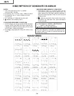
Page 14: ...picture unless otherwise indicated 2 All voltages measured with 1000µ V B W or Color signal WAVEFORM MEASUREMENT CONDITIONS 1 Photographs taken on a standard gated color bar signal the tint setting adjusted for proper color The wave shapes at the red green and blue cathodes of the picture tube depend on the tint color level and picture control 2 indicates waveform check points See chart waveforms ...

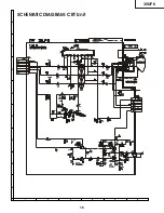
Page 15: ...6 5 4 3 2 1 A B C D E F G H SCHEMATIC DIAGRAM CRT Unit QEARCA009WJZZ QEARCA009WJZZ VB89AJZ90X 1E VB89AJZ90X 1E DUNTKA527WEE2 DUNTKA527WEE2 708 708 7001GEFWY 7001GEFWY 35UF6 15 ...

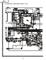
Page 16: ...14 R714 3 3K 3 3K 3 3K D706 D706 D706 1SS133 1SS133 1SS133 D710 D710 D710 EX0650GE EX0650GE EX0650GE C782 C782 C782 1000P 1000P 1000P A B C D E F G H 10 9 8 7 6 5 4 3 2 1 SCHEMATIC DIAGRAM MAIN 1 Unit 35UF6 16 ...

Page 17: ...17 16 19 18 15 14 13 12 11 10 ISS119 ISS119 ISS119 ISS119 ISS119 ISS119 35UF6 17 ...

Page 18: ...A B C D E F G H 10 9 8 7 6 5 4 3 2 1 SCHEMATIC DIAGRAM MAIN 2 Unit 35UF6 18 ...

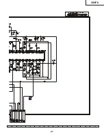
Page 19: ...17 16 19 18 15 14 13 12 11 10 35UF6 19 ...

Page 20: ...A B C D E F G H 10 9 8 7 6 5 4 3 2 1 SCHEMATIC DIAGRAM 3 LINE Y C Unit 35UF6 20 ...

Page 21: ...17 16 19 18 15 14 13 12 11 10 35UF6 21 ...

Page 22: ...A B C D E F G H 10 9 8 7 6 5 4 3 2 1 SCHEMATIC DIAGRAM MODULE D F Unit 35UF6 22 ...

Page 23: ...ZA023WJZZ ZA023WJZZ ZA023WJZZ ZA022WJZZ ZA022WJZZ ZA022WJZZ 17 16 19 18 15 14 13 12 11 10 35UF6 23 ...

Page 24: ...24 6 5 4 3 2 1 A B C D E F G H PWB A MAIN Unit Components Side PRINTED WIRING BOARD ASSEMBLIES 35UF6 ...

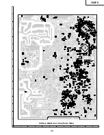
Page 25: ...25 6 5 4 3 2 1 A B C D E F G H PWB A MAIN Unit Chip Parts Side 35UF6 ...

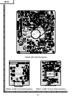
Page 26: ...26 6 5 4 3 2 1 A B C D E F G H PWB C 3 LINE Y C Unit Wiring Side PWB B CRT Unit Wiring Side PWB C 3 LINE Y C Unit Chip Parts Side 35UF6 ...

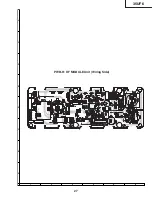
Page 27: ...27 6 5 4 3 2 1 A B C D E F G H PWB H DF MODULE Unit Wiring Side 35UF6 ...

Page 28: ...89Q 2Y X AM IC1403 VHIPQ05RDA1 1 X AF IC2001 RH IXA418WJZZQ X AQ IC2040 VHIKIA7045A 1 X AC IC2101 VHIBR24L16F 1Y X AE IC3001 VHICXA2194Q 1Y X AR Q201 VS2SC2735 1EY X AB Q361 VS2SB709AR 1Y X AA Q401 VS2SD601AR 1Y X AA Q402 VS2SB709AR 1Y X AA Q403 VS2SD601AR 1Y X AA Q404 VS2SD601AR 1Y X AA Q451 VS2SA1266 Y 1 X AB Q460 VSRT1N441C 1Y X AB Q471 VS2SD601AR 1Y X AA Q472 VS2SD601AR 1Y X AA Q473 VS2SD601AR...

Page 29: ...RS AND COILS Ref No Part No Description Code L231 VP XF680K0000Y X Peaking 68mH AA L301 VP XF8R2K0000Y X Peaking 8 2mH AA L401 VP XF100K0000Y X Peaking 10mH AA L671 RCILZ1005CEZZ X LZ1005CE AE L701 RCILF0345CEZZ X Coil AE L702 RCILF0345CEZZ X Coil AE L705 RCILP0179CEZZ X Coil AB L728 RCILP0179CEZZ X Coil AB L729 RCILP0179CEZZ X Coil AB L801 VP XF100K0000Y X Peaking 10mH AA L802 VP XF100K0000Y X Pe...

Page 30: ...EL AE C731 RC EZ0385CEZZ X 1000 16V EL AC Ref No Part No Description Code C732 VCKYPA2HB102K X 1000p 500V Ceramic AA C733 VCKYPA2HB102K X 1000p 500V Ceramic AA C734 VCKYPA2HB471K X 470p 500V Ceramic AA C735 VCKYPA2HB471K X 470p 500V Ceramic AA C736 VCKYCY1HF103ZY X 0 01uF 50V Ceramic AA C737 VCEA0A1HW226M X 22 50V EL AA C738 VCFPVC3CA102H X 1000p 1250V M Poly AC C739 RC EZ0385CEZZ X 1000 16V EL AC...

Page 31: ... RJ14 VRS CY1JF000JY X 00 1 16W M Ox AA RJ15 VRS CY1JF000JY X 00 1 16W M Ox AA RJ16 VRS CY1JF000JY X 00 1 16W M Ox AA RJ19 VRS CY1JF000JY X 00 1 16W M Ox AA RJ20 VRS CY1JF000JY X 00 1 16W M Ox AA RJ21 VRS CY1JF000JY X 00 1 16W M Ox AA RJ22 VRS CY1JF000JY X 00 1 16W M Ox AA RJ23 VRS CY1JF000JY X 00 1 16W M Ox AA RJ24 VRS CY1JF000JY X 00 1 16W M Ox AA RJ25 VRS CY1JF000JY X 00 1 16W M Ox AA RJ30 VRS ...

Page 32: ... Code U R621 VRN RL3AB3R3J X 3 3 1W M Film AB U R622 VRN RL3ABR47J X 0 47 1W M Film AB U R623 VRN RL3AB4R7J X 4 7 1W M Film AB U R624 VRS RG3DB332J X 3 3k 2W M Ox AB U R627 VRN RL3ABR47J X 0 47 1W M Film AB U R628 VRN RL3ABR47J X 0 47 1W M Film AB p U R651 VRS RG2HC270J X 27 1 2W M Ox AB p U R652 VRD RA2EE103GY X 10k 1 4W Carbon AA p U R653 VRD RA2EE562GY X 5 6k 1 4W Carbon AA p U R654 VRD RA2BE56...

Page 33: ...33JY X 33k 1 16W M Ox AA R982 VRS CY1JF750JY X 75 1 16W M Ox AA R983 VRS CY1JF473JY X 47k 1 16W M Ox AA R984 VRS CY1JF473JY X 47k 1 16W M Ox AA U R1420 VRN RL3LB2R7J X 2 7 3 0W M Film AC R2001 VRS CY1JF102JY X 1k 1 16W M Ox AA R2004 VRS CY1JF101JY X 100 1 16W M Ox AA R2008 VRS CY1JF102JY X 1k 1 16W M Ox AA R2010 VRS CY1JF102JY X 1k 1 16W M Ox AA R2013 VRS CY1JF682JY X 6 8k 1 16W M Ox AA R2021 VRS ...

Page 34: ...Carbon AA R873 VRD RM2HD224JY X 220k 1 2W Carbon AA R874 VRD RM2HD104JY X 100k 1 2W Carbon AA Ref No Part No Description Code R2606 VRS CY1JF000JY X 00 1 16W M Ox AA R3001 VRS CY1JF221JY X 220 1 16W M Ox AA R3002 VRS CY1JF221JY X 220 1 16W M Ox AA R3003 VRS CY1JF105JY X 1M 1 16W M Ox AA R3004 VRS CY1JF104JY X 100k 1 16W M Ox AA R3005 VRS CY1JF623JY X 62k 1 16W M Ox AA R3007 VRS CY1JF332JY X 3 3k 1...

Page 35: ...H120JY X 12pF 50V Ceramic AA C1423 VCCCCY1HH3R0CY X 3p 50V Ceramic AA C1424 VCCCCY1HH270JY X 27p 50V Ceramic AA C1425 VCCCCY1HH100DY X 10p 50V Ceramic AA C1428 VCKYCY1HF103ZY X 0 01uF 50V Ceramic AA C1435 VCKYCY1HF103ZY X 0 01uF 50V Ceramic AA C1436 VCKYCY1CF104ZY X 0 1 16V Ceramic AA C1439 VCE9GA1CW106M X 10 16V EL AB C1440 VCEA0A1HW106M X 10 50V EL AA C1441 VCKYCY1HF103ZY X 0 01uF 50V Ceramic AA...

Page 36: ...KT3LB122J X 1 2k 3W M Ox AD R1656 VRD RA2BE394JY X 390k 1 8W Carbon AA R1657 VRD RA2BE683JY X 68k 1 8W Carbon AA R1658 VRD RA2BE183JY X 18k 1 8W Carbon AA R1659 VRD RA2BE102JY X 1k 1 8W Carbon AA R1680 VRS KT3LB154J X 150k 3W M Ox AD R1681 VRS KT3LB104J X 100k 3W M Ox AD R1682 VRC MA2HG333KY X 33k 1 2W Solid AB R1683 VRD RA2BE332JY X 3 3k 1 8W Carbon AA R1684 VRD RA2BE681JY X 1 5k 1 8W Carbon AA R...

Page 37: ...f No Part No Description Code 1 CCABAA003WEH7 X BQ 1 1 Not Available 1 2 HBDGB3141CESA X AF 1 3 HDECQA010WJSA X AE 1 4 HDECQ0104GJKA X AH 1 5 JBTN A004WJKA X AK 1 6 JBTN A005WJKA X AK 1 7 HINDPA433WJSA X AB 1 8 GDORFA001WJKD X AF 2 GCABBA002WJKB X BH Door SHARP Badge Speaker Decoretion RC Cover Indication Plate Button Power Button Vol up down CH up down FrontCabinet assy FrontCabinet Rear Cabinet ...

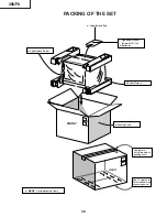
Page 38: ... Not replacement items FRONT Buffer Material Polyethylene Sheet Polyethylene Bag Operation Manual Infrared R C Unit Batteries REAR Use tape to fix the top side of packing case Use 12 staples to fix the bottom side of packing case 35UF6 38 ...

Page 39: ...s electronic mechanical photocopying recording or otherwise without prior written permission of the publisher SHARP ELECTRONICA MEXICO S A DE C V Quality Reliability Control Center Blvd SHARP No 3510 Parque Industrial Rosarito Playas de Rosarito México B C 22710 QRC0023 U June 2004 J B Design and Production Information Design base JAPAN Production SEMEX Modify SEMEX 35UF6 ...

Reviews: