17
32SF670
Sub-picture and Sub-Bright Adjustments
1. Receive the window pattern signal.
•
RF INPUT (TU1101)
2. Get into service adjustment data "V01" and "V04"
and set the luminance as shown in figure "A" and
"B" as below respectively.
•
COMPONENT INPUT
3. Get in service adjustment data "V11" and "V14" and
set the luminance as shown in figure "A" and "B" as
below respectively.
LUMINESCENCE CONFIRMATION
A: 95±10cd/m
2
B: 1.5±0.5cd/m
2
•
DIGITAL RF INPUT (TU1101)
4. Get in service adjustment data "V21", "V24".
4-1 Input data of “V21” = “V01” + 05 STEPS.
4-2 Input data of “V24” = “V04” + 40 STEPS.
Sub-Tint Adjustment
1. Receive the half color bar signal.
•
RF INPUT (TU1101)
2. Get into Y-Mute by R/C, or by setting the "V95" bus
data to "01".
3. Vary the "V02" bus data until the waveform becomes
as stated below.
4. Reset "V95" bus data to "00".
•
Component Input
5. Get into Y-Mute by R/C, or by setting the "V95" bus
data to "01".
6. Vary the "V12" bus data until the waveform becomes
as stated below.
7. Reset "V95" bus data to "00".
•
Digital RF Input (TU1101)
8. Input data of "V22" = "V02" + 13 steps.
9. Reset "V95" bus data to "00".
A
B
Sub-Color Adjustment
1. Receive a good local channel.
2. Make sure the customer color control is set to center
position .
•
RF INPUT (TU1101)
3. Enter the service mode and select service adjustment
"V03".
4. Adjust "V03" data value to obtain a normal color level.
•
Component Input
5. Enter the service mode and select service adjustment
“V13”.
6. Adjust “V13” data value to obtain a normal color level.
•
Digital RF Input (TU1101).
7. Input data of “V23” = “V03” + 50 steps.
Focus Adjustment
1. Receive a good local channel.
2. Adjust the FOCUS VR of the flyback transformer to
make the image as fine as possible.
C. C Display Position Adjustment
1. Receive the lion head pattern signal.
2. Select "V113" to display the text box.
3. Adjust the "V113" bus data to let the text box displayed
in the center.
Vertical-Size, Linearity and VS-Correct
Adjustments
1. Receive a good local channel.
(SCREEN FORMAT 4:3)
2. Enter the service mode and select the service
adjustment "D04" for V-size.
3. Adjust the "D04" bus data to get the proper V-size.
4. For V-linearity adjustment, select data bus "D07" and
adjust to get the proper vertical linearity.
5. For VS-Correct adjustment, select data bus "D06"
and adjust to get the proper VS-Correction.
(SCREEN FORMAT 16:9)
6. Input data of "D14" to minus 33 steps from "D04” data.
(V-SIZE)
7. Input data of "D17" to minus 3 steps from "D07” data.
(V-LIN)
8. Input data of "D16" is plus 14 steps of data "D06".
(VS-CORRECT)
Note:
Aging for 10 min before adjustment. After the
adjustment of V-center and V-size, re-
adjustment for this V-line.
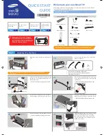
DISPLAY OF TEXT BOX
TEXT BOX
A
B
| A-B | / 2
SPEC INSPECTION:| A-B | / 2 <
= 5mm
B-AMP Base waveform in step
(TP47B)
LEVEL
Summary of Contents for 32SF670
Page 19: ...19 32SF670 M E M O ...
Page 20: ...20 32SF670 CHASSIS LAYOUT ...
Page 21: ...21 32SF670 BLOCK DIAGRAM ...
Page 23: ...23 8 7 10 9 6 5 4 3 2 1 A B C D E F G H 32SF670 SCHEMATIC DIAGRAM CRT Unit ...
Page 24: ...24 8 7 10 9 6 5 4 3 2 1 A B C D E F G H 32SF670 SCHEMATIC DIAGRAM MAIN 1 Unit ...
Page 25: ...25 17 16 19 18 15 14 13 12 11 10 32SF670 ...
Page 26: ...26 8 7 10 9 6 5 4 3 2 1 A B C D E F G H 32SF670 SCHEMATIC DIAGRAM MAIN 2 Unit ...
Page 27: ...27 17 16 19 18 15 14 13 12 11 10 32SF670 ...
Page 28: ...28 8 7 10 9 6 5 4 3 2 1 A B C D E F G H 32SF670 SCHEMATIC DIAGRAM 2 LINE Y C Unit ...
Page 29: ...29 17 16 19 18 15 14 13 12 11 10 32SF670 ...
Page 30: ...30 8 7 10 9 6 5 4 3 2 1 A B C D E F G H 32SF670 SCHEMATIC DIAGRAM CONTROL Unit ...
Page 31: ...31 17 16 19 18 15 14 13 12 11 10 32SF670 ...
Page 33: ...33 17 16 19 18 15 14 13 12 11 10 32SF670 ...
Page 34: ...34 8 7 10 9 6 5 4 3 2 1 A B C D E F G H 32SF670 PWB A MAIN Unit Components side ...
Page 35: ...35 17 16 19 18 15 14 13 12 11 10 32SF670 ...
Page 37: ...37 8 7 10 9 6 5 4 3 2 1 A B C D E F G H 32SF670 PWB F CONTROL Unit Wiring Side ...