background image

32K-S400, CK32S40
36K-S400, CK36S40

32K-S400, CK32S40
36K-S400, CK36S40

H

G

F

E

D

C

B

A

1

2

3

4

5

6

7

8

9

10

11

12

15

16

H

G

F

E

D

C

B

A

1

2

3

4

5

6

DESCRIPTION OF SCHEMATIC DIAGRAM

NOTES:
1. The unit of resistance "ohm"  is omitted.
  (K=k

=1000

,  M=M

)

2. All resistors are 1/8  watt, unless  otherwise noted.
3. All capacitors are µ F, unless otherwise noted.

(P=pF=µµF)

4. (G)  indicates ±2% tolerance may be used.
5.

 indicates line isolated ground.

6.

 indicates hot  ground.

VOLTAGE MEASUREMENT CONDITIONS:
1. All DC voltages are measured with DVM connected

between points indicated and chassis ground, line
voltage set at 120V AC and all controls set  for  normal
picture unless otherwise indicated.

2. All voltages measured with 1000µ V B & W or Color

signal.

WAVEFORM MEASUREMENT  CONDITIONS:
1. Photographs taken on a standard gated color bar

signal, the tint  setting adjusted for proper color. The
wave shapes at the red, green and blue  cathodes of
the picture tube depend on the tint, color level and
picture control.

2.         indicates waveform check points (See chart,

waveforms are measured  from  point indicated to
chassis ground.)

å


AND SHADED (

   )  COMPONENTS

= SAFETY RELATED PARTS.

'

MARK= X-RAY RELATED PARTS.

DRGANNES MARQUES 

å

 ET HACHRES (            ):

PIECES RELATIVES A LA SECURITE.
MARQUE 

'

 : PIECS RELATIVE AUX RAYONS X.

This circuit diagram is a standard one, printed circuits
may be subject to change for product improvement
without prior notice.

WAVE FORMS

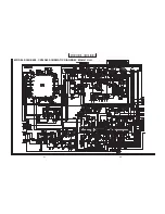
SCHEMATIC DIAGRAM: CRT Unit

MODELS 32K-S400, CK32S40

MODELS 36K-S400, CK36S40

Summary of Contents for 32K-S400

Page 1: ...ASSEMBLIES 27 REPLACEMENT PARTS LIST 33 PACKING OF THE SET 46 Page CONTENTS Specifications are subject to change without prior notice AUDIO POWER OUTPUT RATING 2 5W 2 5W at 10 distortion and Dual CH Operate SPEAKER SIZE 12 cm x 6 cm 2pcs VOICE COIL IMPEDANCE 8 ohm at 400 Hz ANTENNA INPUT IMPEDANCE VHF UHF 75 ohm Unbalanced TUNING RANGES VHF Channels 2 thru 13 UHF Channels 14 thru 69 CATV Channels ...

Page 2: ...oltage with a meter to be certain that the high voltage does not exceed the specified value and that it is regulating correctly 5 Do not use a picture tube other than that specified or make unrecommended circuit modifications to the high voltage circuitry 6 When trouble shooting and taking test measurements on a receiver with excessive high voltage avoid being unnecessarily close to the receiver D...

Page 3: ...t and compartment covers or shields isolation resistor capacity networks mechanical insulators etc 3 To be sure that no shock hazard exists check for leakage current in the following manner Plug the AC cord directly into a 120 volt AC outlet Do not use an isolation transformer for this test Using two clip leads connect a 1 5k ohm 10 watt resistor paralleled by a 0 15µF capacitor in series with all...

Page 4: ...anipuler le tube image qu en porant des lunettes incassables et qu après avoir déchargé totalement la haute tension LIMITES DES RADIATIONS X ET DE LA HAUTE TENSION 1 Tout le personnel réparateur doit être instruit des instructions et procédés relatifs aux radiations X Le tube image seule source de rayons X dons les téleviseurs transistorisés n émet pourtant pas de rayons mesurables si la haute ten...

Page 5: ...les isolateurs mécaniques etc 3 S assurer qu il n y ait pas de danger d électrocution en vérifiant la fuite de courant de la facon suivante Brancher le cordon d alimentation directem ent à une prise de courant de 120V Ne pas utiliser de transformateur d isolation pour cet essai A l aide de deux fils à pinces brancher une résistance de 1 5 kΩ 10 watts en parallèle avec un condensateur de 0 15µF en ...

Page 6: ...6 32K S400 CK32S40 36K S400 CK36S40 LOCATION OF USER S CONTROL ...

Page 7: ...n the screen 7 If the operation of the horizontal oscillator does not stop in step 5 the circuit must be repaired before the set is returned to the customer HIGH VOLTAGE CHECK High voltage is not adjustable but must be checked to verify that the receiver is operating within safe and efficient design limitations as specified checks should be as follows 1 Connect an accurate high voltage meter betwe...

Page 8: ... in the normal mode Use the reset function in the video adjustment menu to ensure customer controls are in their proper reset position 2 Service number selection Once in the service mode press the Ch up or Ch down button on the remote controller or at the set The service adjustment number will vary in increments of one from S01 to P07 Select the item you wish to adjust 3 Data number selection Pres...

Page 9: ...03 COLOR 32 00 7F S04 BRIGHTNESS 40 00 7F S05 SHARPNESS 24 00 3F Must be set to 24 S06 VERTICAL PHASE 00 00 07 Must be set to 00 S07 HORIZONTAL PHASE 12 00 1F S08 RF AGC 23 00 3F S09 VERTICAL AMP 20 00 3F S10 VCO 2C 00 7F S11 R CUT OFF 00 00 FF S12 G CUT OFF 00 00 FF S13 B CUT OFF 00 00 FF S14 G GAIN 7F 00 FF S15 B GAIN 7F 00 FF S16 TRAP 3 58MHz 00 00 or 01 Must be set to 01 S17 BALANCE 20 00 3F M...

Page 10: ...en 6 Adjust the service adjustments S11 red S12 green and S13 blue to obtain a good grey scale with normal whites at low brightness level 7 Select the service adjustment S19 and reset data to 00 Select the service adjustment S03 and reset data to obtain normal color level 8 Reset the master screen control to obtain normal brightness range White Balance Adjustment 1 Receive a good local channel 2 E...

Page 11: ...mode and select the service adjustment S18 3 A black text box appears on the screen see Figure B below 4 Adjust S18 data value so that text box is positioned in the center of the screen 3 58MHz Trap Adjustment 1 Receive a good local channel 2 Enter the service mode and select the service adjustment S16 3 This is a two position adjustment 00 is ON 01 is OFF 4 Adjust data value to 01 for normal view...

Page 12: ...ading of the RMS voltmeter is minimum 5 Receive the following composite stereo signal 2 Stereo signal 30 modulation left channel only noise reduction on 3kHz 6 Enter the service mode and select the service adjustment M05 7 Adjust the data until the AC voltage reading of the RMS voltmeter is minimum 8 Take the above steps 1 thru 8 again for fine adjustment P IN P Y LEVEL Adjustment 1 Receive a good...

Page 13: ...13 32K S400 CK32S40 36K S400 CK36S40 H G F E D C B A 1 2 3 4 5 6 CHASSIS LAYOUT PWB R PWB F PWB B PWB A ...

Page 14: ...14 32K S400 CK32S40 36K S400 CK36S40 H G F E D C B A 1 2 3 4 5 6 BLOCK DIAGRAM ...

Page 15: ...picture unless otherwise indicated 2 All voltages measured with 1000µ V B W or Color signal WAVEFORM MEASUREMENT CONDITIONS 1 Photographs taken on a standard gated color bar signal the tint setting adjusted for proper color The wave shapes at the red green and blue cathodes of the picture tube depend on the tint color level and picture control 2 indicates waveform check points See chart waveforms ...

Page 16: ...32K S400 CK32S40 36K S400 CK36S40 H G F E D C B A 1 2 3 4 5 6 7 8 9 10 11 12 32K S400 CK32S40 36K S400 CK36S40 17 18 MODELS 32K S400 CK32S40 SCHEMATIC DIAGRAM MAIN 1 Unit ...

Page 17: ...32K S400 CK32S40 36K S400 CK36S40 32K S400 CK32S40 36K S400 CK36S40 H G F E D C B A 1 2 3 4 5 6 7 8 9 10 11 12 19 20 MODELS 32K S400 CK32S40 SCHEMATIC DIAGRAM MAIN 2 Unit ...

Page 18: ...32K S400 CK32S40 36K S400 CK36S40 H G F E D C B A 1 2 3 4 5 6 7 8 9 10 11 12 32K S400 CK32S40 36K S400 CK36S40 MODELS 36K S400 CK36S40 SCHEMATIC DIAGRAM MAIN 1 Unit 21 22 ...

Page 19: ...32K S400 CK32S40 36K S400 CK36S40 32K S400 CK32S40 36K S400 CK36S40 H G F E D C B A 1 2 3 4 5 6 7 8 9 10 11 12 23 24 MODELS 36K S400 CK36S40 SCHEMATIC DIAGRAM MAIN 2 Unit ...

Page 20: ...32K S400 CK32S40 36K S400 CK36S40 H G F E D C B A 1 2 3 4 5 6 7 8 9 10 11 12 32K S400 CK32S40 36K S400 CK36S40 SCHEMATIC DIAGRAM P IN P CONTROL Unit 25 26 ...

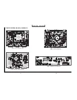
Page 21: ...32K S400 CK32S40 36K S400 CK36S40 H G F E D C B A 1 2 3 4 5 6 7 8 9 10 11 12 PRINTED WIRING BOARD ASSEMBLIES 27 28 PWB R P IN P Unit Wiring Side PWB R P IN P Unit Chip Parts Side PWB F CONTROL Unit Wiring Side PWB B CRT Unit Wiring Side ...

Page 22: ...32K S400 CK32S40 36K S400 CK36S40 H G F E D C B A 1 2 3 4 5 6 7 8 9 10 11 12 32K S400 CK32S40 36K S400 CK36S40 29 30 PWB A MAIN Unit Wiring Side ...

Page 23: ...32K S400 CK32S40 36K S400 CK36S40 32K S400 CK32S40 36K S400 CK36S40 H G F E D C B A 1 2 3 4 5 6 7 8 9 10 11 12 31 32 PWB A MAIN Unit Chip Parts Side ...

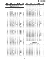
Page 24: ...NOTE THE PARTS HERES SHOWN ARE SUPPLIED AS AN ASSEMBLY NOT INDEPENEDENTLY å TU51 VTU115B8025AM M Tuner INTEGRATED CIRCUITS IC101 VHiKA78S05P 1 J KIA78S05P AD çå IC201 RH iX2933CEZZ J TA1268N AX å IC361 RH iX1135CEZZ J LA4261 AH IC470 VHiM52055FP 1 J M52055FP AH å IC501 VHiTA8427K 1 J TA8427K AL or RH iX1224CEZZ AH IC671 VHiUPC358C 1 J UPC358C AD çå IC701 VHiSTRF65161E J STR F6516 å IC702 RH FX0002...

Page 25: ...601 RTRNZ0057PEZZ R H driver AK çå T602 RTRNF0021MEZZ J H out 32K S400 CK32S40 çå T602 RTRNF0022MEZZ J H out 36K S400 CK36S40 å T701 RTRNP0518CEZZ J Power AN å T702 RTRNZ0006MEZZ J Transformer CONTROLS R502 RVR M4334CEZZ J 10k B V line AC R676 RVR M4334CEZZ J 10k B H line AC R678 RVR M4336CEZZ J 22k B H size AC CAPACITORS EL Electrolytic M Poly Metalized Polypro Film C51 VCEA0A1CW476M J 47 16V EL ...

Page 26: ...472K J 4700p 50V Ceramic AA C608 RC KZ0033CEZZ J 150p 2kV Ceramic 32K S400 CK32S40 C608 VCKYPH3DB271K J 270p 2kV Ceramic AC 36K S400 CK36S40 çå C609 VCFPPD3CA912H J 9100p 1 6kV M Poly 32K S400 CK32S40 çå C609 VCFPPD3CA822H J 8200p 1 6kV M Poly AE 36K S400 CK36S40 çå C610 VCFPPD3CA912H J 9100p 1600V M Poly AE C615 VCKYPA2HB272K J 2700p 500V Ceramic AA C622 VCKYPA2HB102K J 1000p 500V Ceramic AA C623...

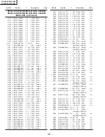
Page 27: ...1HH101J J 100p 50V Ceramic AA C2062 VCEA0A1AW107M J 100 10V EL AB C2063 VCKYCY1HF103Z J 0 01 50V Ceramic AA C2201 VCKYCY1HB472K J 4700p 50V Ceramic AA C2202 VCCCCY1HH390J J 39p 50V Ceramic AA C3001 VCE9GA1HW475M J 4 7 50V EL N P AB C3002 VCKYCY1HB562K J 5600p 50V Ceramic AA C3003 RC QZA123TAYK J 0 012 50V Mylar AB C3004 VCEA0A1HW105M J 1 50V EL AB C3005 VCEA0A1HW475M J 4 7 50V EL AB C3006 VCEA0A1H...

Page 28: ...rbon AA R411 VRD RA2BE682J J 6 8k 1 8W Carbon AA R412 VRD RA2EE561J J 560 1 4W Carbon AA R413 VRS CY1JF101J J 100 1 16W M Ox AA R414 VRS CY1JF101J J 100 1 16W M Ox AA R415 VRS CY1JF101J J 100 1 16W M Ox AA R419 VRS CY1JF225J J 2 2M 1 16W M Ox AA R420 VRS CY1JF332J J 3 3k 1 16W M Ox AA R421 VRS CY1JF152J J 1 5k 1 16W M Ox AA R424 VRS CY1JF102J J 1k 1 16W M Ox AA R426 VRS CY1JF182J J 1 8k 1 16W M Ox...

Page 29: ...2 2k 1 16W M Ox AA R680 VRS CY1JF822J J 8 2k 1 16W M Ox AA R681 VRS CY1JF123J J 12k 1 16W M Ox AA R682 VRS CY1JF102J J 1k 1 16W M Ox AA R683 VRD RA2BE102J J 1k 1 8W Carbon AA R684 VRS CY1JF472J J 4 7k 1 16W M Ox AA R685 VRD RA2BE562J J 5 6k 1 8W Carbon AA R686 VRD RA2EE222J J 2 2k 1 4W Carbon AA R687 VRS CY1JF103J J 10k 1 16W M Ox AA å R688 VRN RL3DB3R3J M 3 3 2W M Film R689 VRS CY1JF274J J 270k 1...

Page 30: ...1k 1 8W Carbon AA R2004 VRD RA2BE473J J 47k 1 8W Carbon AA R2006 VRS CY1JF102J J 1k 1 16W M Ox AA R2008 VRD RA2BE102J J 1k 1 8W Carbon AA R2009 VRD RA2BE102J J 1k 1 8W Carbon AA R2010 VRS CY1JF102J J 1k 1 16W M Ox AA R2011 VRD RA2BE821J J 820 1 8W Carbon AA R2012 VRS CY1JF471J J 470 1 16W M Ox AA R2020 VRD RM2HD223J J 22k 1 2W Carbon AA R2022 VRS CY1JF103J J 10k 1 16W M Ox AA R2024 VRD RA2BE682J J...

Page 31: ... DUNTK9513WEK0 32K S400 CK32S40 PWB A DUNTK9513WEK1 36K S400 CK36S40 MAIN UNIT Continued PWB B DUNTK9303WEK3 32K S400 CK32S40 PWB B DUNTK9303WEK4 36K S400 CK36S40 CRT UNIT TRANSISTORS Q850 VS2SC4544LB2E J 2SC4544 AD Q851 VS2SC4544LB2E J 2SC4544 AD Q852 VS2SC4544LB2E J 2SC4544 AD Q853 VS2SC3198 Y 1 J 2SC3198 Y AA Q854 VS2SC3198 Y 1 J 2SC3198 Y AA Q855 VS2SC3198 Y 1 J 2SC3198 Y AA Q894 VS2SA1266 Y 1...

Page 32: ...ANEOUS PARTS P860 QPLGN0461CEZZ J Plug 4 pin YBN AB P880 QPLGN0561CEZZ J Plug 5 pin GBN AB SC801 QSOCV0937CEZZ J Socket 32K S400 CK32S40 AF or QSOCV0938CEZZ SC801 QSOCV1011CEZZ J Socket 36K S400 CK36S40 PWB B DUNTK9303WEK3 32K S400 CK32S40 PWB B DUNTK9303WEK4 36K S400 CK36S40 CRT UNIT Continued CAPACITOR EL Electrolytic C4001 VCEA0A1HW475M J 4 7 50V EL AB RESISTORS R4001 VRD RA2BE103J J 10k 1 8W C...

Page 33: ... 33 16V EL AB C1811 VCKYCY1HF103Z J 0 01 50V Ceramic AA C1812 VCEA0A1HW106M J 10 50V EL AB C1821 VCKYCY1HF103Z J 0 01 50V Ceramic AA C1822 VCEA0A1HW106M J 10 50V EL AB C1841 VCEA0A1HW106M J 10 50V EL AB C1842 VCKYCY1HF103Z J 0 01 50V Ceramic AA C1843 VCCCCY1HH680J J 68p 50V Ceramic AA C1845 VCKYCY1HB103K J 0 01 50V Ceramic AA C1846 VCCCCY1HH151J J 150p 50V Ceramic AA C1847 VCKYCY1HB103K J 0 01 50V...

Page 34: ... VRS CY1JF272J J 2 7k 1 16W M Ox AA R1834 VRS CY1JF222J J 2 2k 1 16W M Ox AA R1841 VRS CY1JF153J J 15k 1 16W M Ox AA R1842 VRS CY1JF471J J 470 1 16W M Ox AA R1843 VRS CY1JF391J J 390 1 16W M Ox AA R1861 VRS CY1JF153J J 15k 1 16W M Ox AA R1862 VRS CY1JF102J J 1k 1 16W M Ox AA R1863 VRS CY1JF102J J 1k 1 16W M Ox AA R1864 VRS CY1JF331J J 330 1 16W M Ox AA R1865 VRS CY1JF474J J 470k 1 16W M Ox AA R186...

Page 35: ...1 Not Available Front Cabinet 1 2 GCOVA1039MEKA M Cover for R C 1 3 HBDGB1009MESA M Badge SHARP AD 1 4 JBTN 1105MEKA M Button Power Vol up down AE CH up down 2 GCABB1134MEKA M Rear Cabinet 36K S400 CK36S40 1 CCABA1301MES0 M Front Cabinet Ass y 1 1 Not Available Front Cabinet 1 2 GCOVA1039MEKA M Cover for R C 1 3 HBDGB1010MESA M Badge SHARP 1 4 JBTN 1105MEKA M Button Power Vol up down AE CH up down...

Page 36: ...S40 36K S400 CK36S40 REAR Use 22 staples fix the packing case Bar Code Label Packing Case Serial Number Label MARK Not replacement items Number Card FRONT Buffer Material Polystyrene Mat Polystyrene Bag Infrared R C unit Operation Manual Guarantee Card Batteries PACKING OF THE SET ...

Page 37: ...Ref No Part No Description Code Ref No Part No Description Code 47 32K S400 CK32S40 36K S400 CK36S40 Memo ...

Page 38: ... part of this publication may be reproduced stored in a retrleval system or transmitted in any form or by any means electronic mechanical photocopying recording or otherwise without prior written permission of the publisher TQ0440 S Mar 1998 Printed in Japan YO KG SHARP CORPORATION AV Systems Group Quality Reliability Control Center Yaita Tochigi 329 21 Japan ...

Reviews: