background image

- 17 -

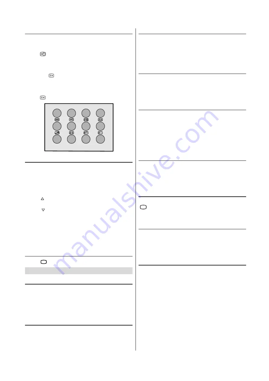
To Select a Subcode Page

Subcode pages are subsections of long Teletext pages that
can only be displayed on the screen one section at a time.
• Select the required Teletext page.

• Press “

“ button.

• Select the required subcode page number by pressing four

digit buttons (e.g. 0001).

•  If  the  selected  subcode  page  is  not  displayed  in  a  short

time, press “

“ button. TV programme will be displayed on

the screen.

•  Teletext  page  number  will  be  displayed  on  the  upper  left

corner of the screen when the selected page is found.

• Press “

“button to display the selected Teletext page.

Fastext

Teletext mode will be selected according to transmission au-
tomatically.

Your  TV  supports  the  7  page  Teletext  system.  When  the
page number of any of the 7 pages in memory is entered, the
system will not search for the requested page; instead it will
display the page automatically.

• Press “

” button  to move the Teletext screen forward one

page at a time.

•  Press  “

”  button    to  move  the Teletext  screen  backward

one page at a time.

For Fastext

The subject-heading for the information may have a particular
colour or can be in a form located in a coloured box.

• Press an appropriate 

RED, GREEN, YELLOW 

or

 BLUE

 but-

ton in order to reach the relevant page quickly.

To exit Teletext

• Press “

79

” button. The screen will switch to TV mode.

Connecting  external  equipment

Via the Euro connector

Your TV set has two euro connector sockets. If you wish to
connect  external  equipment  (e.g.  video  recorder,  decoder,
etc.) which have Euro connectors, to your TV, use


the 

EXT.1

(EXT-1) 

or

 EXT.2 (EXT-2) 

terminals.

If an external device is connected via Euro connector sockets
the TV will be switched to AV mode automatically.

RGB mode

If a piece of equipment outputs 

RGB

 signals use the 

EXT-1

Euro connector as this is 

RGB

 ready.

EXT-2S Mode

If the equipment connected to your TV set supports S-Video
(Y/C) output from Euroconnector, you can have a better pic-
ture quality by selecting 

EXT-2S

 mode and connecting your

equipment to the 

EXT.2 (EXT-2S)

 terminal of TV. See your

equipment's  booklet  to  check  if  your  equipment  has  such
feature.

Via the RCA jacks

If you have an equipment (such as a Camcorder) which has
the  RCA  jacks,  connect  it  to  the 

Front AV


(F-AV)

  terminal

with the video and audio cables.

• If the equipment has the mono audio jack, connect it to the

AUDIO-L

 jack.

Via the ANT (aerial) socket

If your equipment does not have an Euroconnector or RCA
jacks, connect it to the TV with an aerial cable. For details,
see the manual provided with the equipment.

•  To  store  the  test  signal  that  comes  from  the  equipment,

see “

INSTALL. Menu

” on 

page 13 

and store it to the pro-

gramme number 0. You can watch images from that equip-
ment to select the programme number which you stored the
test signal.

TV and Video Recoder (VCR)

•  Connect  the  Video  Recorder  to  the  ANT  (antenna  input)

socket of the TV with the aerial cable.

• Connect the Video Recorder to the 

EXT.1 

or 

EXT.2

 terminal

with the SCART cable, or connect it to the 

Front AV


(F-AV)

terminal with the audio and video cables.

NTSC Playback

Connect  a  NTSC  video  recorder  to  a  terminal.  Then  press

“

(;7

” button to select the corresponding AV mode.

NTSC  3.58/4.43

  system  is  detected  automatically  in  AV

mode.

Copy Facility

You can output the video and audio signals which inputs from

TV 

or 

EXT.1


(EXT-1)

 terminal to the video recorder connected

to the 

EXT.2 (EXT-2)

 terminal.

• To select the output source, see “

Setting External Source

Output

” on 

page 13

.

Connecting Headphones

Use  the  stereo  headphone  socket  of  your  TV,  to  connect
headphones.

Downloaded from: 

http://www.usersmanualguide.com/

Summary of Contents for 28LW-92H

Page 1: ...R Please read this operation manual carefully before using the colour television 28LW 92H 32LW 92H COLOUR TELEVISION OPERATION MANUAL Downloaded from http www usersmanualguide com ...

Page 2: ...inued 22 Typical Connections Continued 23 21 pin Euro SCART and 21 pin Audio Video 24 Troubleshooting 25 Specifications 26 Important Instructions 27 Dear SHARP Customer 2 Safety Precautions 3 Supplied Accessories 5 Remote Control Buttons 6 Control Panel Buttons 7 Antenna Connections 7 Preparation 8 Features 8 Before Switching on your TV 8 Power connection 8 Aerial Connections 8 How to connect exte...

Page 3: ...s guarantee does not apply to equipment used in the course of a business trade or profession 3 This guarantee does not cover any faults or defects caused by accident misuse fair wear and tear neglect tampering with the equipment or any attempt at adjustment or repair other than by an approved Service Facility 4 In the unlikely event of that your equipment should require repair please contact the d...

Page 4: ...abinet Television equipment and cart combination should be moved with care Quick stops excessive force and uneven surfaces may cause the equipment and cart combination to overturn To prevent electrical shock do not subject the AC power cord to damage by bending or twisting it or by placing heavy items on top of it and do not place the AC power cord under the TV set If the AC power cord becomes dam...

Page 5: ...ng kit approved by the manufacturer Do place the TV set onto an even stand table or track which size is bigger than the TV set If the TV set is put onto a smaller size or uneven stand table or track may cause the TV cabinet distort Do not put or in sert anything between TV set and the stand table or track The tube of your TV has a special coating Do not knock or rub on the tube face with sharp or ...

Page 6: ... 4XLFN 6WDUW XLGH 2SHUDWLRQ 0DQXDO 7 SH 5 U DWWHULHV 7 SLFDO RQQHFWLRQV 3OHDVH UHDG WKLV RSHUD WLR Q PDQX DO F DUHIXOO E HIRUH XVLQ J WKH FR OR XU WHOH YLVLR Q 2 285 7 9 6 21 23 5 7 21 0 18 2 285 7 9 6 21 48 67 57 8 RU HDV LQVWDOODWLRQ 8VLQJ WKLV LQVWDOODWLRQ JXLGH VKRXOG HQDEOH RX WR VHW XS RXU 79 LQ OHVV WKDQ PLQXWHV 5HIHU WR RXU RSHUDWLRQ PDQXDO IRU PRUH WLSV DQG DGYLFH I SUREOHPV SHUVLVW FRQWD...

Page 7: ...alert the user to the presence of important operating and maintenance servicing instructions in the literature accompanying the appliance Stand By Cursor Up Cursor Right OK OK Info Program Menu 0 9 Direct Program Double Digit Wide mode button P CH Program Volume TV Quit Menu 7 EXT button EXT 1 RGB EXT 2 EXT 2S F AV Yellow Feature Menu Blue Installation Menu Hold Update Index Page Reveal Expand Mix...

Page 8: ... PANEL REAR PANEL Speakers left right Power On Off Volume P CH Program MENU Menu AUDIO L Audio left AUDIO R Audio right VIDEO VCR Headphone 3 6 mm Ø ANT Antenna 75 W EXT 1 Scart Socket 1 with RGB EXT 2 Scart Socket 2 with SVHS Power Cable Downloaded from http www usersmanualguide com ...

Page 9: ...ndicated by the arrow to remove the battery cover 2 Insert two batteries 1 5 V R03 AAA size Be sure to match the battery terminals with the marks inside the compartment 9 5 3 Replace the battery cover Notes Remove batteries if weak or if the unit is not in use for long periods Do not mix old and new batteries Incorrect installation of the batteries may damage the re mote control Switching the TV O...

Page 10: ...layed on the screen Programme Selecting Press P CH button to select next programme or P CH button to select the previous programme Entering Main Menu Press MENU button to enter main menu In the main menu select submenu using P CH or P CH button and enter the submenu using or button To learn the usage of the menus refer to Menu System on page 9 Operating with Remote Control The remote control hands...

Page 11: ...phone menu To do this select headphone using or button then enter headphone menu pressing or button 92 80 1 6281 02 6855281 3 21 9 48 5 0212 2 21 Setting Headphone Volume As you enter the Headphone sound menu Volume will be the first selected option Press button to increase the headphone volume Press button to decrease the headphone volume 92 80 6281 02 6725 0212 Setting Headphone Sound Mode Using...

Page 12: ... picture mode is selected Using or button select Brightness Press button to increase Brightness Press button to decrease Brightness 5 71 66 21 75 67 2 285 6 5 31 66 3 785 02 2 285 7 03 02 0 18 125 0 872 Setting Contrast You can change the Contrast setting only when manual pic ture mode is selected Using or button select Contrast Press button to increase Contrast level Press button to decrease Cont...

Page 13: ...ode and receives the VPS sig nal it changes the size automatically as indicated below When the TV is receiving VPS code 16 9 the TV selects CINEMA automatically When the TV is receiving VPS code 14 9 the TV selects ZOOM 14 9 automatically When the TV is receiving VPS code 4 3 the TV selects NORMAL automatically When the TV does NOT receive VPS code the TV selects FULL automatically External source...

Page 14: ... control panel buttons except the POW ER button with this item Press or button to change the setting to On or Off af ter selecting this item When you set this item to On the TV can be operated only by using the remote control handset 6 3 7 0 5 2 1 8 7 28 7387 8 52 81 2 2 1 6 79 21 Language Menu Language can be selected by pressing or but ton on Language item 6 3 7 0 5 2 1 8 7 28 7387 8 52 81 2 2 1...

Page 15: ...TORE then press or button to store it 781 1 02 1 11 2 285 6 67 0 1 781 1 6 5 6725 11 6 3 8 When you select Frequency Search the display of the Tuning menu will be as below 352 5 00 781 1 02 2 285 6 67 0 5 48 1 6 5 6725 3 5 48 1 3 As Frequency Search is selected TV will search ac cording to the channel frequencies With the or button select Search Search can be made either forward pressing button or...

Page 16: ...E 1 Choose the channel you want to delete 2 Press the YELLOW button to enter the DELETE mode 3 Press the YELLOW button to delete it To cancel this DELETE mode press the BLUE button To change the programme number of a channel INSERT 1 Choose the channel you want to change the programme number 2 Press the GREEN button to enter the INSERT mode 3 Press button to choose new programme number 4 Press the...

Page 17: ...tents index is displayed on the screen To select a page of Teletext Press the appropriate digit buttons for the required Teletext page number The selected page number is displayed at the top left corner of the screen The Teletext page counter searches until the selected page number is located so that the desired page is displayed on the screen Press button to move the Teletext screen forward one p...

Page 18: ...ece of equipment outputs RGB signals use the EXT 1 Euro connector as this is RGB ready EXT 2S Mode If the equipment connected to your TV set supports S Video Y C output from Euroconnector you can have a better pic ture quality by selecting EXT 2S mode and connecting your equipment to the EXT 2 EXT 2S terminal of TV See your equipment s booklet to check if your equipment has such feature Via the RC...

Page 19: ...R inputs and RGB inputs are available TV broadcast outputs Video and Audio L R are available EXT 2 EXT 2 terminal Euroconnector 21 pin SCART Video input S VIDEO Y C input and Audio L R inputs are available Video and Audio L R outputs are available see Setting External Source Output on page 13 Front AV F AV terminal RCA connectors x 3 Video input and Audio L R inputs are available 7 7 QWHQQD 7 7 5 ...

Page 20: ...Q 79 VHW RQO HULDO 1 2 79 HULDO 1RW VXSSOLHG HULDO HDG 1RW VXSSOLHG 21752 17 7 7 HULDO RQQHFWLRQV 79 DQG 9 5 HULDO 1RW VXSSOLHG HULDO HDG 1RW VXSSOLHG 21752 17 7 7 HULDO HDG 1RW VXSSOLHG 6FDUW HDG 1RW VXSSOLHG 2 79 HULDO 1 2 9 5 XGLR 9LGHR 5 287 9 7 50 1 9 HULDO 1 Downloaded from http www usersmanualguide com ...

Page 21: ...ODER and VCR RQQHFWLRQV 79 9 3OD HU 2 5 DQG 9 5 9LGHRUHFRUGHU 9 7 50 1 9 2 79 9 3 5 2 5 6FDUW HDG 1RW VXSSOLHG 6FDUW HDG 1RW VXSSOLHG 9 7 50 1 9 HULDO 1 6FDUW HDG 1RW VXSSOLHG HULDO HDG 1RW VXSSOLHG HULDO 1RW VXSSOLHG HULDO HDG 1RW VXSSOLHG HULDO 1 XGLR 9LGHR 2 9 5 5 287 Downloaded from http www usersmanualguide com ...

Page 22: ... Top Box RQQHFWLRQV 79 9 3OD HU DQG LJLWDO 6HW 7RS R 2 79 17 7 7 9 3 5 6FDUW HDG 1RW VXSSOLHG 9 7 50 1 9 HULDO 1 HULDO 1RW VXSSOLHG 6DWHOOLWH GLVK 1RW VXSSOLHG LVK HDG 1RW VXSSOLHG HULDO HDG 1RW VXSSOLHG 6FDUW HDG 1RW VXSSOLHG HULDO HDG 1RW VXSSOLHG 7 6 7 723 2 5 287 5 1 79 6 57 6 1 Downloaded from http www usersmanualguide com ...

Page 23: ... LJLWDO 6HW 7RS R 2 79 17 7 7 9 3 5 6FDUW HDG 1RW VXSSOLHG HULDO 1 9 7 50 1 9 HULDO 1RW VXSSOLHG 6DWHOOLWH GLVK 1RW VXSSOLHG LVK HDG 1RW VXSSOLHG HULDO HDG 1RW VXSSOLHG 6FDUW HDG 1RW VXSSOLHG 7 6 7 723 2 2 9 5 HULDO HDG 1RW VXSSOLHG 6FDUW HDG 1RW VXSSOLHG 5 287 HULDO 1 XGLR 9LGHR HULDO HDG 1RW VXSSOLHG 5 287 5 1 79 6 57 6 1 Downloaded from http www usersmanualguide com ...

Page 24: ...nual of your Video Camera 2 79 RQQHFWLRQ 79 SRZHU FDEOH WR D a 9 V VWHP 0DLQV 6RFNHW 2XWOHW a 9 5 5217 79 XGLR 9LGHR OHDG 1RW VXSSOLHG XGLR QSXW 7 HUPLQDO OHIW 9LGHR QSXW 7 HUPLQDO XGLR QSXW 7 HUPLQDO ULJKW URQW FRQQHFWLRQV 79 DQG 9LGHR FDPHUD Downloaded from http www usersmanualguide com ...

Page 25: ...1 Green input 18 Earth for Red Green Blue control 5 Earth for blue 12 Not used 19 Video output 6 Audio left input 13 Earth for red 20 Video input PAL SECAM NTSC 7 Blue input 14 Not used 21 Plug shield 21 pin Audio Video AV 2 with S Video Input EXT 2 1 Audio right output 8 Audio video control 15 Chroma S Video input 2 Audio right input 9 Earth 16 Not used 3 Audio left output 10 Not used 17 Earth fo...

Page 26: ...ILQH WXQLQJ WR FRUUHFW HULDO QRW FRQQHFWHG WR WHUPLQDO DW WKH EDFN RI WKH 79 VHW 1R FRORXU 3LFWXUH ZHDN 7U D QHZ FKDQQHO WR FKHFN IRU SRVVLEOH VWDWLRQ WURXEOH HULDO QRW FRQQHFWHG WR WHUPLQDO DW WKH EDFN RI WKH 79 VHW I RXWVLGH DHULDO LV XVHG FKHFN IRU EURNHQ ZLUHV KHFN IRU ORFDO LQWHUIHUHQFH 3RRU UHFHSWLRQ RQ VRPH FKDQQHOV 7U D QHZ FKDQQHO WR FKHFN IRU SRVVLEOH VWDWLRQ WURXEOH HULDO QRW FRQQHFWHG ...

Page 27: ...lanced OPERATING VOLTAGE 220 240V AC 50 Hz POWER CONSUMPTION W 28LW 92H 85 Watt POWER CONSUMPTION W 32LW 92H 110 Watt Power Consumption at Stand by 4 Watts Audio Output RMS 2x10 W AUDIO OUTPUT Nicam Stereo PICTURE TUBE 28 16 9 32 16 9 Safety CE MARK EMC CE MARK DIMENSIONS DxLxH mm 28LW 92H HLJKW NJ 0 16 216 DIMENSIONS DxLxH mm 32LW 92H HLJKW NJ 0 16 216 Downloaded from http www usersmanualguide co...

Page 28: ...cordance with the following code IMPORTANT As the colours of the wires in the mains lead of this appliance may not correspond with the coloured markings identifying the terminals in your plug proceed as follows The wire which is coloured blue must be connected to the terminal which is marked with the letter N or coloured black The wire which is coloured brown must be connected to the terminal whic...

Page 29: ...SHARP ELECTRONICS U K LTD Sharp House Thorp Road Newton Heath Manchester M40 5BE R SHARP CORPORATION 50044952 11 03 50044952 Downloaded from http www usersmanualguide com ...

Page 30: ...Downloaded from http www usersmanualguide com ...

Page 31: ... and VCR Aerial Not supplied Aerial Lead Not supplied ANT EXT 2 EXT 1 Aerial Lead Not supplied Scart Lead Not supplied BACK OF TV Aerial IN BACK OF VCR Audio Video RF OUT AV TERMINAL AV 1 Aerial IN Typical Connections 28 32LW 92H Note For further details please refer to operation manual of your VCR 1 Downloaded from http www usersmanualguide com ...

Page 32: ...Aerial IN Aerial Not supplied Satellite dish Not supplied Dish Lead Not supplied Aerial Lead Not supplied Scart Lead Not supplied Aerial Lead Not supplied DIGITAL SET TOP BOX RF OUT AERIAL IN TV SCART DISH IN Note For further details please refer to operation manuals of your DVD Player and Digital Set Top Box 2 Downloaded from http www usersmanualguide com ...

Page 33: ...R FRONT TV Audio Video lead Not supplied Audio Input Terminal left Video Input Terminal Audio Input Terminal right Note For further details please refer to operation manual of your Video Camera 3 Downloaded from http www usersmanualguide com ...

Page 34: ...tings The message will be displayed when you turn on your TV for the first time PLEASE CHECK ANTENNA CABLE AUTO PROGRAMMING SYSTEM 1 LANGUAGE 2 COUNTRY 3 4 START A P S A P S A P S A P S IS RUNNING PLEASE WAIT A P S PROGRAM A P S Select with or button then press the or button to select a menu language Select with or button then press the or button to select the country you are now located Press the...

Page 35: ...cture setting mode might be all the way to the minus side Try a new channel to check for possible station trouble Check for local interference Increase the volume Check Audio levels Picture OK poor sound Try a new channel to check for possible station trouble TV not plugged in Outlet power OFF Main power button of TV not ON Aerial not connected to terminal at the back of the TV set If outside aeri...

Page 36: ...SHARP ELECTRONICS U K LTD Sharp House Thorp Road Newton Heath Manchester M40 5BE R SHARP CORPORATION 50046867 11 03 50046867 Downloaded from http www usersmanualguide com ...

Page 37: ... tv dvd and othes Manual users user manuals user guide manual owners manual instruction manual manual owner manual owner s manual guide manual operation operating manual user s manual operating instructions manual operators manual operator manual product documentation manual user maintenance brochure user reference pdf manual Downloaded from http www usersmanualguide com ...

Reviews: