


21K-FD5RU
2 – 1
TV
21K-FD5RU
Service Manual
21K-FD5RU
Market
E
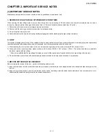
CHAPTER 2.
IMPORTANT SERVICE NOTES
[1] IMPORTANT SERVICE NOTES
Maintenance and repair of this receiver should be done by qualified service personnel only.
1. SERVICE OF HIGH VOLTAGE SYSTEM AND PICTURE TUBE
When servicing the high voltage system, remove static charge from it by connecting a 10K ohm resistor in series with an insulated wire ( such as a
test probe ) between picture tube dag and 2nd anode lead. ( AC line cord should be disconnected from AC outlet. )
1) Picture tube in this receiver employs integral implosion protection.
2) Replace with the same type number of picture tube for continued safety.
3) Do not lift picture tube by the neck.
4) Handle the picture tube only when wearing shatterproof goggles and after discharging the high voltage completrly.
2. X-RAY
This receiver is designed so that any X-Ray radiation is kept to an absolute minimum. Since certainmalfunctions or servicing may produce potentially
hazardous radiation with prolonged exposure at close range, the following precautions should be observed :
1) When repairing the circuit, please make sure do not increase the high voltage of the set to more that 30.0kV ( at beam 0
µ
A ).
2) To keep the set in a normal operation, please make sure it’s function at 26.2kV
±
1.0kV ( at beam 1150
µ
A ). The set has been factory - adjusted to
the above -mentioned high voltage.
* If there is a possibility that the hig voltage fluctuates as a result of the repairs,never forget to checkfor such high voltage after the work.
3) Do not substitute a picture tube with unauthorized types and/or brands which may cause excessive X-ray radiation.
3. BEFORE RETURNING THE RECEIVER
Before returning the receiver to the user , perform the following safety checks.
1) Inspect all lead dress to make certain that leads are not pinched or that hardware is not lodged between the chassis and other metal parts in the
receiver.
2) Inspect all protective devices such as non-mental control knobs, insulating materials,cabinet backs,adjustment and compartment cover or
shields,isolation resistor-capacity networks,mechanical insulators etc.
Summary of Contents for 21K-FD5RU
Page 21: ...21K FD5RU 3 18 2 ADJUSTMENT 1 PIF ADJUSTMENT CHECKING 2 PURITY ADJUSMENT ...
Page 22: ...21K FD5RU 3 19 3 CONVERGENCE ADJUSTMENT 4 H VCO VIF VCO S TRAP for ADJUSTMENT ...
Page 27: ...21K FD5RU 3 24 15 FUNCTION OPERATION CHECKING 2 VIDEO AUDIO CONTINUED ...
Page 59: ...21K FD5RU 5 2 TROUBLE SHOOTING Continued pin 11 pin 13 of SC304 ...
Page 60: ...21K FD5RU 5 3 TROUBLE SHOOTING Continued I I I I ...
Page 62: ...21K FD5RU 7 1 CHAPTER 7 CHASSIS LAYOUT 1 CHASSIS LAYOUT A C B D E F G H 1 2 3 4 5 6 7 8 9 10 ...
Page 64: ...21K FD5RU 8 2 10 11 12 13 14 15 16 17 18 19 ...
Page 66: ...21K FD5RU 8 4 4 BLOCK DIAGRAM NICAM UNIT A C B D 1 2 3 4 5 6 7 8 9 10 ...
Page 70: ...21K FD5RU 11 2 3 SCHEMATIC DIAGRAM NICAM UNIT A C B D 1 2 3 4 5 6 7 8 9 10 ...
Page 71: ...21K FD5RU 11 3 4 SCHEMATIC DIAGRAM MAIN UNIT A C B D E F G H 1 2 3 4 5 6 7 8 9 10 ...
Page 72: ...21K FD5RU 11 4 10 11 12 13 14 15 16 17 18 19 ...
Page 74: ...21K FD5RU 12 2 10 11 12 13 14 15 16 17 18 19 ...
Page 75: ...21K FD5RU 12 3 2 MAIN UNIT Chip Parts Side A C B D E F G H 1 2 3 4 5 6 7 8 9 10 ...
Page 76: ...21K FD5RU 12 4 10 11 12 13 14 15 16 17 18 19 ...
Page 96: ...www s manuals com ...


