background image

4

20SL43

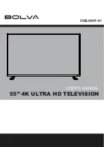
LOCATION OF USER'S CONTROL

TV

Infrared Transmitter Window

INPUT
Press

 Switch to external video input

mode.
Press again 

 Switch to TV mode.

Press 

 Switch to external video

INPUT 1 mode.
Press 2 times 

 Switch to external

video INPUT 2 mode.

CHANNEL UP/DOWN
(

'

) Selects next higher channel.

(

"   

) Selects next lower channel.

• Moves the “

” mark of the MENU

screen.

MENU
Press

 Accesses MAIN MENU.

Press again 

 Exits MAIN MENU.

DISPLAY
Press

 Displays receiving channel for

4 seconds.
Press again

 Removes display.

• Temporarily displays receiving

channel when in Closed Caption
mode.

Front Panel

CHANNEL UP/DOWN
(

'

) Selects next higher channel.

(

"

) Selects next lower channel.

VOLUME UP/DOWN
(+) Increases sound.
(–) Decreases sound.

Basic Remote Control Functions

POWER
Press

 On.

Press again 

 Off.

REMOTE KEYPAD
Accesses any channel from keypad.

FLASHBACK
Returns to previous channel.

VOLUME UP/DOWN
(+) Increases sound.
(–) Decreases sound.
• In menu mode, changes or selects

the TV adjustments.

MUTE
Press

 Mutes sound.

Press again 

 Restores sound.

•  CLOSED CAPTION appears when

sound is muted.

MENU
Press ; Accesses MAIN MENU.

Press again ; Exits MAIN MENU.

VIDEO/AUDIO  

IN

  TERMINALS

(VIDEO/AUDIO terminals are also 
provided on the rear.)

ON TIMER indicator.

SENSOR AREA FOR
REMOTE CONTROL

POWER
Press

 On.

Press again 

 Off.

www.DataSheet.net/

Datasheet pdf - http://www.DataSheet4U.co.kr/

Summary of Contents for 20SL43

Page 1: ...9 Page CONTENTS SERVICE MANUAL MODELS POWER INPUT 110 220 V AC 50 60 Hz POWER RATING 72 W PICTURE SIZE 1 194 cm2 185sq inch CONVERGENCE Magnetic SWEEP DEFLECTION Magnetic FOCUS QPF Electrostatic INTERMEDIATE FREQUENCIES Picture IF Carrier Frequency 45 75 MHz Sound IF Carrier Frequency 41 25 MHz Color Sub Carrier Frequency 42 17 MHz Nominal AUDIO POWER OUTPUT RATING 1 5 1 5 W at 10 distortion ELECT...

Page 2: ...alue and that it is regulating correctly 5 Do not use a picture tube other than that specified or make unrecommended circuit modifications to the high voltage circuitry 6 When trouble shooting and taking test measurements on a receiver with excessive high voltage avoid being unnecessarily close to the receiver Do not operate the receiver longer than is necessary to locate the cause of excessive vo...

Page 3: ... etc 3 To be sure that no shock hazard exists check for leakage current in the following manner Plug the AC cord directly into a 110 220 volt AC outlet Do not use an isolation transformer for this test Using two clip leads connect a 1 5k ohm 10 watt resistor paralleled by a 0 15µF capacitor in series with all exposed metal cabinet parts and a known earth ground such as electrical conduit or electr...

Page 4: ...on mode Front Panel CHANNEL UP DOWN Selects next higher channel Selects next lower channel VOLUME UP DOWN Increases sound Decreases sound Basic Remote Control Functions POWER Press On Press again Off REMOTE KEYPAD Accesses any channel from keypad FLASHBACK Returns to previous channel VOLUME UP DOWN Increases sound Decreases sound In menu mode changes or selects the TV adjustments MUTE Press Mutes ...

Page 5: ...1 5 V 5 Apply external 27 9V DC at TP653 by using an external DC supply TV must be shut off 6 To reset the protector unplug the AC cord and make a short circuit between TP651 and TP652 Now make sure that normal picture appears on the screen 7 If the operation of the horizontal oscillator does not stop in step 5 the circuit must be repaired before the set is returned to the customer HIGH VOLTAGE CH...

Page 6: ...rols are in their proper reset position 2 Service item selection Once in the service mode press the Ch up or Ch down button on the remote controller or at the set The service adjustment item will vary in increments of one Select the item you wish to adjust 3 Data number selection Press the Vol up or down button to adjust the data number To enter the service mode and exit serv ice mode Short JA137 ...

Page 7: ...E W P RED OFFSET HIGH OFFSET BLUE TONE DRI R HI W P GREEN OFFSET HIGH OFFSET BLUE TONE DRI G HI W P BLUE OFFSET HIGH OFFSET BLUE TONE DRI B HI W P RED MH STD DRI R MH W P GREEN MH STD DRI G MH W P BLUE MH STD DRI B MH W P RED OFFSET ML OFFSET RED TONE DRI R ML W P GREEN OFFSET ML OFFSET RED TONE DRI G ML W P BLUE OFFSET ML OFFSET RED TONE DRI B ML W P RED OFFSET LOW DRI R LO W P GREEN OFFSET LOW D...

Page 8: ...UR LIMIT ACL FORCED COLOUR ON FCO VIDEO MUTE AT IDENT LOSS VMI VIDEO MUTE AT PROGRAM SOURCE CHANGE VMC HOTEL MODE HTL GAIN FM DEMODULATOR BTSC CHARGE PUMP CP FM WINDOW SELECTION FMWS SOUND MUTE BIT 0 SM0 SOUND MUTE BIT 1 SM1 IF AGC SPEED BIT 0 AGC0 IF AGC SPEED BIT 1 AGC1 PHI 1 TIME CONSTANT FOR FE FOA FE PHI 1 TIME CONSTANT FOR FE FOB FE PHI 1 TIME CONSTANT FOR AV FOA AV PHI 1 TIME CONSTANT FOR A...

Page 9: ...OL MAX HOTEL VOLUME 0 63 32 FIX HTL PRG HOTEL PROGRAM NO 0 125 or 125 for none 255 FIX BB CON BLUE BACK CONTRAST 0 15 10 FIX must be 5 RGB OSD GRB REFERENCE 0 15 15 FIX must be 5 CUT R BLACK LEVEL OFFSET R 0 63 32 ADJ CUT G BLACK LEVEL OFFSET G 0 63 32 ADJ CDL CATHODE DRIVE LEVEL 0 15 0 FIX must be 6 DL TV Y D TIME TV YD 0 15 12 FIX must be 2 DL AV Y D TIME AV YD 0 15 12 FIX must be 8 INIT INITIAL...

Page 10: ...1 enable 0 FIX FAO FIXED AUDIO OUT 0 disable or1 enable 0 FIX VIEW TM VIEW TIMER 0 disable or1 enable 1 FIX must be 1 FRENCH FRENCH LANGUAGE 0 disable or1 enable 0 FIX EZ SETUP EZ SETUP AUTOPRESET 0 AUTOPRESET or 1 FIX 1 EZ SETUP W TEMP WHITE TEMP OR FAVORITE COLOR 0 FC or 1 WT 0 FIX AV AV ENABLED OR DISABLED 0 without ext source or 0 FIX 1 with external source AV2 AV2 ENABLED OR DISABLED 0 1 inpu...

Page 11: ...d 1 Call the V AMP mode 2 Increase or decrease V AMP by Volume key to set overscan of 10 0 typical Adjustment Spec 10 0 range 1 FIXED DATA NO NEED TO ADJUST 1 Call the H CENT mode 2 Increase or decrease H CENT by Volume key to center the picture horizontal 1 2 3 4 5 Focus adjustment 1 Receive the Monoscope Pattern signal 2 Press R C to set Picture NORMAL condition 3 Adjust the focus control to get...

Page 12: ...nally line 5 will be the brighter than line 4 2 1 2 3 are in same black level WHITE BAL ANCE SERV ICE MODE ADJ I2C BUS CONTROL 3 11 600 K X 0 273 Y 0 280 MINOLTA COLOUR ANALYZER CA 100 NOTE Above DATA can be UP DOWN by volume key LOW HIGH 20 1 8cd m2 115cd m2 11 600 K DRI GW DRI GS DATA 5 DRI BW DRI BS DATA 5 1 Receive the Monoscope Pattern signal 2 Press R C to set Picture NORMAL condition 3 Conn...

Page 13: ...13 6 5 4 3 2 1 A B C D E F G H 20SL43 MODEL 20SL43 CHASSIS LAYOUT www DataSheet net Datasheet pdf http www DataSheet4U co kr ...

Page 14: ...14 6 5 4 3 2 1 A B C D E F G H 20SL43 BLOCK DIAGRAM 1 www DataSheet net Datasheet pdf http www DataSheet4U co kr ...

Page 15: ...16 20SL43 15 12 11 10 9 8 7 6 5 4 3 2 1 A B C D E F G H MODEL 20SL43 BLOCK DIAGRAM 2 www DataSheet net Datasheet pdf http www DataSheet4U co kr ...

Page 16: ...e tint setting adjusted for proper color The wave shapes at the red green and blue cathodes of the picture tube depend on the tint color level and picture control 2 indicates waveform check points See chart waveforms are measured from point indicated to chassis ground å AND SHADED COMPONENTS SAFETY RELATED PARTS MARK X RAY RELATED PARTS This circuit diagram is a standard one printed circuits may b...

Page 17: ...12 11 10 9 8 7 6 5 4 3 2 1 A B C D E F G H MODEL 20SL43 BLOCK DIAGRAM 2 20SL43 18 19 www DataSheet net Datasheet pdf http www DataSheet4U co kr ...

Page 18: ...20 6 5 4 3 2 1 A B C D E F G H 20SL43 SCHEMATIC DIAGRAM CRT Unit www DataSheet net Datasheet pdf http www DataSheet4U co kr ...

Page 19: ...21 6 5 4 3 2 1 A B C D E G H 20SL43 PWB A MAIN Unit Wiring Side PRINTED WIRING BOARD ASSEMBLIES www DataSheet net Datasheet pdf http www DataSheet4U co kr ...

Page 20: ...22 6 5 4 3 2 1 A B C D E F G H 20SL43 PWB A MAIN Unit Chip Parts Side www DataSheet net Datasheet pdf http www DataSheet4U co kr ...

Page 21: ...23 6 5 4 3 2 1 A B C D E F G H 20SL43 PWB B CRT Unit Wiring Side PWB B CRT Unit Chip Parts Side www DataSheet net Datasheet pdf http www DataSheet4U co kr ...

Page 22: ... 2SC2735 AB Q253 VS2SD601AR 1Y X 2SD601AR AB Q254 VS2SD601AR 1Y X 2SD601AR AB Q321 VS2SD601AR 1Y X 2SD601AR AB Q601 VS2SC3207 1 X 2SC3207 AT AB Q602 VS2SD2586 1E X 2SD2586 AF Q603 VS2SC3198 G 1 X 2SC3198 G AB Q751 VS2SC3198 G 1 X 2SC3198 G AB Q752 VS2SC3198 G 1 X 2SC3198 G AB Q801 VS2SB709AR 1Y X 2SB709AR AB Q802 VS2SB709AR 1Y X 2SB709AR AB D201 RH EX0676GEZZY X Zener Diode 32V AB U D331 RH DX0302...

Page 23: ...EW106M X 10 250V EL AB C605 VCKYPA2HB102K X 1000p 500V Ceramic AB C606 VCFPVC2DB474J X 0 47 200V M Poly AB C607 VCFPVC3ZA772H X 7700p 1 5kV M Poly AB C608 VCKYPA2HB102K X 1000p 500V Ceramic AB C610 VCEA0A1CW108M X 1000 16V EL AB C611 VCEA0A1EW476M X 47 25V EL AB C612 VCEA0A1CW477M X 470 16V EL AB C620 VCKYPA2HB102K X 1000p 500V Ceramic AB C640 VCFYSB2EB823J X 0 082 250V M Poly AB C651 VCQYTA1HM222...

Page 24: ... AA R311 VRS CY1JF473JY X 47k 1 16W M Ox AA R313 VRS CY1JF102JY X 1k 1 16W M Ox AA R314 VRS CY1JF103JY X 10k 1 16W M Ox AA R315 VRS CY1JF822JY X 8 2k 1 16W M Ox AA R322 VRS CY1JF272JY X 2 7k 1 16W M Ox AA R323 VRD RA2BE274JY X 270k 1 8W Carbon AA R333 VRS CY1JF101JY X 100 1 16W M Ox AA R334 VRS CY1JF332JY X 3 3k 1 16W M Ox AA R335 VRS CY1JF564JY X 560k 1 16W M Ox AA R364 VRS CY1JF000JY X 00 1 16W ...

Page 25: ... X Switch AB S1004 QSW KA003WJZZ X Switch AB S1005 QSW KA003WJZZ X Switch AB S1006 QSW K0114CEZZ X Switch AC PWB A DUNTKA541WEC6 MAIN UNIT RESISTORS M Ox Metal Oxide M Film Metal Film SWITCHES Ref No Part No Description Code U F701 QFS C3229CEZZ X Fuse T3 14AL AB FB601 RBLN 0091GEZZY X Ferrite Bead AB FH701 QFSHD1013CEZZ X FUSE CLIP AB FH702 QFSHD1014CEZZ X FUSE CLIP AB J402 QJAKE0210CE04 X Jack V...

Page 26: ... AB LHLDZ0063PEZZ X HOLDER Insulator Ring AB LX TZ3004CEFD X SCREW AA QCNW 2562PEZZ X WIRE SPEAKER AC TLABM0005GJZZ X Model Label AB TLABN0101GJZZ X Remark label chassis ID AB TLABZ0204GJZZ X Case Label AB TINS 7668GJZZ X Operation Manual AD RRMCG1339CESB X Infrared R C Unit AH TCAUH0102GJZZ X Caution Card AA TCAUS3000GJZZ X CAUTION LABEL AA MISCELLANEOUS PARTS SUPPLIED ACCESORRIES Ref No Part No ...

Page 27: ... the packing case Use tape to fix top side of pack case Packing Case FRONT Buffer Material Wrapping Paper Polyethylene Bag Operation Manual Infrared R C Unit Batteries MARK Not Replacement Items www DataSheet net Datasheet pdf http www DataSheet4U co kr ...

Page 28: ... any form or by any means electronic mechanical photocopying recording or otherwise without prior written permission of the publisher SHARP ELECTRONICA MEXICO S A DE C V Blvd SHARPNo 3510ParqueIndustrial Rosarito Playas de Rosarito B C 22710 D SEM P SEMEX TQ0000 S June 2002 Printed in Japan MI KG www DataSheet net Datasheet pdf http www DataSheet4U co kr ...

Reviews: