


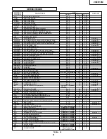


PWB-A: DUNTKD167WEA0
MAIN UNIT
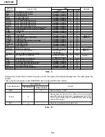
CAPACITORS
[EL.··· Electrolytic, M-Poly.··· Metalized Polypro Film]
DIODES
PACKAGED CIRCUITS
FILTERS AND COILS
TRANSFORMERS
Ref. No. Part No.
«
Description Code
D1023 RH-EX0263TAZZY X EX0263TA AB
U
VA701 RH-VX0073CEZZ X Varistor AC
PR702 RMPTP0026CEZZ X Packaged Circuit AD
X1001 RCRSB0300CEZZ X Crystal AD
CF253 RFILC0446CEZZ X Filter,FiLC0446CE AC
L202 VP-DF270K0000Y X Peaking,27mH AA
L203 VP-DF270K0000Y X Peaking,27mH AA
L204 VP-XF1R2K0000Y X Peaking,1.2mH AA
L253 VP-XF120K0000Y X Peaking,12mH AA
L701 RCILF0078PEZZ X Coil Line Filter AE
L751 RCILP0225CEZZ X Coil, AC
L802 VP-DF100K0000Y X Peaking,10mH AA
L803 VP-DF100K0000Y X Peaking,10mH AA
L1030 VP-DF100K0000Y X Peaking,10mH AA
L1050 VP-DF100K0000Y X Peaking,10mH AA
L1051 VP-DF100K0000Y X Peaking,10mH AA
SF201 RFILC0405CEZZ X Filter,(4.5MHZ) AF
T601 RTRNZ0144PEZZ X Transformer AD
T602 RTRNF0229PEZZ X H-Volt Transformer AS
T701 RTRNW0015PEZZ X Transformer AG
C201
VCEA0A
X
47
16V
EL.
AA
C202
VCEA0A
X
1000
10V
EL.
AB
C205
VCKYCY1HF103ZY
X
0.01
50V
Ceramic AA
C206
VCEA0A
X
1
50V
EL.
AA
C207
VCKYCY1HB103KY
X
0.01
50V
Ceramic AA
C208
VCKYCY1HB103KY
X
0.01
50V
Ceramic AA
C209
VCKYCY1HB103KY
X
0.01
50V
Ceramic AA
C210
VCKYCY1HF103ZY
X
0.01
50V
Ceramic AA
C211
VCKYCY1HF103ZY
X
0.01
50V
Ceramic AA
C231
VCKYCY1HF223ZY
X
0.022
50V
Ceramic AA
C232
VCKYCY1HB821KY
X
820p
50V
Ceramic AA
C233
VCKYCY1HB472KY
X
100
35V
EL.
AA
C234
VCKYCY1EF104ZY
X
0.1
25V
Ceramic AA
C251
VCKYCY1HF223ZY
X
0.022
50V
Ceramic AA
C252
VCEA0A
X
100
16V
EL.
AA
C301
VCEA0A
X
470
16V
EL.
AB
C304
VCEA0A
X
10
50V
EL.
AA
C310
VCEA0A
X
2.2
50V
EL.
AA
C312
VCEA0A
X
2.2
50V
EL.
AA
C313
VCKYCY1HB472KY
X
100
35V
EL.
AA
C332
VCQYTA
X
0.01
50V
Mylar
AA
C333
VCEA0A
X
1000
16V
EL.
AC
C356
VCKYCY1HB472KY
X
100
35V
EL.
AA
C359
VCEA0A
X
10
16V
EL.
AA
C360
VCE9GA
X
1
50V
EL.
AB
C409
VCKYCY1EF104ZY
X
0.1
25V
Ceramic AA
C410
VCKYCY1EF104ZY
X
0.1
25V
Ceramic AA
C411
VCKYCY1HB102KY
X
1000p 50V
Ceramic AA
C504
VCKYCY1HB103KY
X
0.01
50V
Ceramic AA
C505
VCEA0A
X
100
50V
EL.
AB
C507
VCKYCY1HB103KY
X
0.01
50V
Ceramic AA
C508
VCFYSA
X
0.22
63V
Mylar
AC
C509
VCEA0A
X
470
16V
EL.
AB
C510
VCKYPA
X
1000p 500V
Ceramic AA
C514
VCFYSA
X
0.047
63V
Mylar
AB
C531
VCKYCY1HB102KY
X
1000p 50V
Ceramic AA
C532
VCKYCY1HB102KY
X
1000p 50V
Ceramic AA
Ref. No. Part No.
«
Description Code
C533
VCQYTA
X
0.1
50V
Mylar
AB
C601
VCQYTA
X
0.056
50V
Mylar
AA
C602
VCEA0A
X
4.7
50V
EL.
AA
C603
VCEA0A
X
1
50V
EL.
AA
C604
VCEA0A
X
10
250V
EL.
AC
C605
VCKYPA
X
1000p 500V
Ceramic AA
C606
VCFPVC2DB474J
X
0.47
200V
M-Poly.
AC
C607
VCFPVC3ZA772H
X
7700p 1.5kV
M-Poly.
AC
C608
VCKYPA
X
1000p 500V
Ceramic AA
C610
VCEA0A
X
1000
16V
EL.
AC
C611
VCEA0A
X
47
25V
EL.
AA
C612
VCEA0A
X
470
16V
EL.
AB
C620
VCKYPA
X
1000p 500V
Ceramic AA
C621
VCKYD41HB104KY
X
0.1
50V
Ceramic
C640
VCFYSB2EB823J
X
0.082
250V
M.Poly.. AB
C651
VCQYTA
X
2200p 50V
Mylar
AA
C652
VCQYTA
X
4700p 50V
Mylar
AA
C653
VCEA0A
X
1
50V
EL.
AA
C654
VCKYCY1HF223ZY
X
0.022
50V
Ceramic AA
C655
VCEA0A
X
10
50V
EL.
AA
C656
VCEA0A
X
0.22
50V
EL.
AA
C657
VCKYCY1EF104ZY
X
0.1
25V
Ceramic AA
C658
VCKYCY1EF104ZY
X
0.1
25V
Ceramic AA
C701
RC-FZA018WJZZ
X
0.1
AC275V M.Poly.
AB
C702
RC-KZ0
X
0.01
AC250V Ceramic AB
C703 RC-KZ0 X 0.01 AC250V Ceramic AB
C705
RC-EZ0718CEZZ
X
470
200V
EL.
AG
C709
RC-KZ0039CEZZ
X
680
2kV
Ceramic AB
C710
VCEA0A
X
47
50V
EL.
AB
C711
VCKYPA
X
1000p 50V
Ceramic AA
C712
VCKYPA
X
470p
50V
Ceramic AA
C751
RC-KZ0106GEZZ
X
3300p AC250V Ceramic AC
C752
VCKYPH3DB561K
X
560p
2kV
Ceramic AB
C753
RC-EZ0724CEZZ
X
100
160V
EL.
AD
C754
RC-EZ0724CEZZ
X
100
160V
EL.
AD
C755
VCEA0A
X
1000
16V
EL.
AC
C756
VCQYTA
X
0.01
50V
Mylar
AA
C759
VCEA0A
X
470
10V
EL.
AB
C760
VCEA0A
X
2200
6.3V
EL.
AC
C801
VCEA0A
X
1
50V
EL.
AA
C803
VCEA0A
X
100
16V
EL.
AA
C804
VCKYCY1HB222KY
X
2200p 50V
Ceramic AA
C805
VCKYCY1HB102KY
X
1000p 50V
Ceramic AA
C806
VCKYCY1HB102KY
X
1000p 50V
Ceramic AA
C807
VCKYCY1HB102KY
X
1000p 50V
Ceramic AA
C808
VCEA0A
X
100
16V
EL.
AA
C809
VCKYCY1CF474ZY
X
0.47
16V
Ceramic AA
C810
VCKYCY1CF474ZY
X
0.47
16V
Ceramic AA
C811
VCEA0A
X
100
16V
EL.
AA
C812
VCFYFA
X
0.22
50V
Mylar
AB
C813
VCFYFA
X
0.22
50V
Mylar
AB
C814
VCKYCY1HB471KY
X
470p
50V
Ceramic AA
C816
VCKYCY1HB471KY
X
470p
50V
Ceramic AA
C1001 VCEA0A
X
100
6.3V
EL.
AA
C1002 VCEA0A
X
100
6.3V
EL.
AA
C1003 VCEA0A
X
10
16V
EL.
AA
C1004 VCKYCY1CF474ZY
X
0.47
16V
Ceramic AA
C1005 VCKYCY1CF474ZY
X
0.47
16V
Ceramic AA
C1006 VCEA0A
X
10
16V
EL.
AA
C1008 VCCCCY1HH330JY
X
33p
50V
Ceramic AA
C1009 VCCCCY1HH330JY
X
33p
50V
Ceramic AA
C1010 VCEA0A
X
100
6.3V
EL.
AA
C1011 VCKYCY1CF474ZY
X
0.47
16V
Ceramic AA
C1012 VCKYCY1CF474ZY
X
0.47
16V
Ceramic AA
C1013 VCEA0A
X
100
6.3V
EL.
AA
C1016 VCQYTA
X
0.1
50V
Mylar
AB
C1018 VCKYCY1HB221KY
X
220p
50V
Ceramic AA
C1024 VCQYTA
X
0.1
50V
Mylar
AB
C1026 VCEA0A
X
100
6.3V
EL.
AA
20MR10M
17


