8
13VT-N100
13VT-N150
13VT-CN10
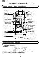
Location Of Control’s Buttons (Remote Control)
LOCATION OF USER'S CONTROL
(Continued)
INPUT
TV/VIDEO Select
POWER ON/OFF
CHANNEL SELECT
FLASHBACK
Returns to previously viewed
channel.
COUNTER RESET
• Used to reset the tape counter.
TAPE SPEED
• Used to select the recording
tape speed.
PLAY
• Used for tape playback.
• Used to cancel the PAUSE/STILL
mode and return to normal
playback operation.
REW
• Used to rewind the tape or to
conduct Reverse Video Search
during playback mode.
REC
• Used to record a program.
–, +
TIMER ON/OFF
CONFIRM
• Used to confirm the program
setting.
RETURN
SET
1
2
3
4
5
6
7
8
9
0
100
POWER
INPUT
DISPLAY
MUTE
VOL
TAPE
SPEED
REC
REW
FF
PLAY
STOP
PAUSE/STILL
COUNTER
RESET
DPSS
FLASHBACK
TAMPER
PROOF
TV • VCR COMBINATION
+
SET
PROG
MENU
TIMER
ON/OFF
CONFIRM
–
—
TR
•
•
•
•
RETURN
CH
•
Infrared Transmitter Window
DISPLAY
• Used to change the On Screen
Display.
MUTE
Press
Mutes sound.
Press again
Restores sound
to previous level.
Press the MUTE button to enter
the CLOSED CAPTION mode
automatically if the signal contains
CC information.
VOLUME UP/DOWN
CHANNEL UP/DOWN
(TRACKING )
• Used to select the CHANNEL.
• Used to adjust the TRACKING
while playing the tape.
TAMPER PROOF
• Used to block changes to current
operating mode.
FF
• Used to fast forward the tape or
to conduct Forward Video Search
during playback mode.
STOP
• Used to stop the tape.
PAUSE/STILL
• Used to temporarily stop the tape
during recording mode.
• Used to display a still picture
during playback mode.
DPSS (
)
• Press the (
—
/
±
—
/
±
—
/
±
) button to search
for the index signal and begin
playback automatically.
PROGRAM
• Press the button to enter the Timer
Recording mode.
MENU
• Used to select the menu screen.
±
—
±
Remote Control Battery Installation
Ë
Before using the television, prepare the Remote Control
To use the remote control, insert batteries first.
Insert the batteries
Battery
Cover
Pull up
• With your thumb nail, pull up the slit as indicated by the arrow to remove the back cover. Insert two batteries (size “AA”).
Be sure to match the battery
±
/
—
terminals with the
±
/
—
marks inside the compartment.
Summary of Contents for 13VT-CN10
Page 69: ...83 6 5 4 3 2 1 A B C D E F G H 13VT N100 13VT N150 13VT CN10 PWB C POWER Unit Wiring Side ...
Page 70: ...84 6 5 4 3 2 1 A B C D E F G H 13VT N100 13VT N150 13VT CN10 PWB A MAIN Unit Wiring Side ...
Page 71: ...85 6 5 4 3 2 1 A B C D E F G H 13VT N100 13VT N150 13VT CN10 PWB A MAIN Unit Chip Parts Side ...


