Tarea
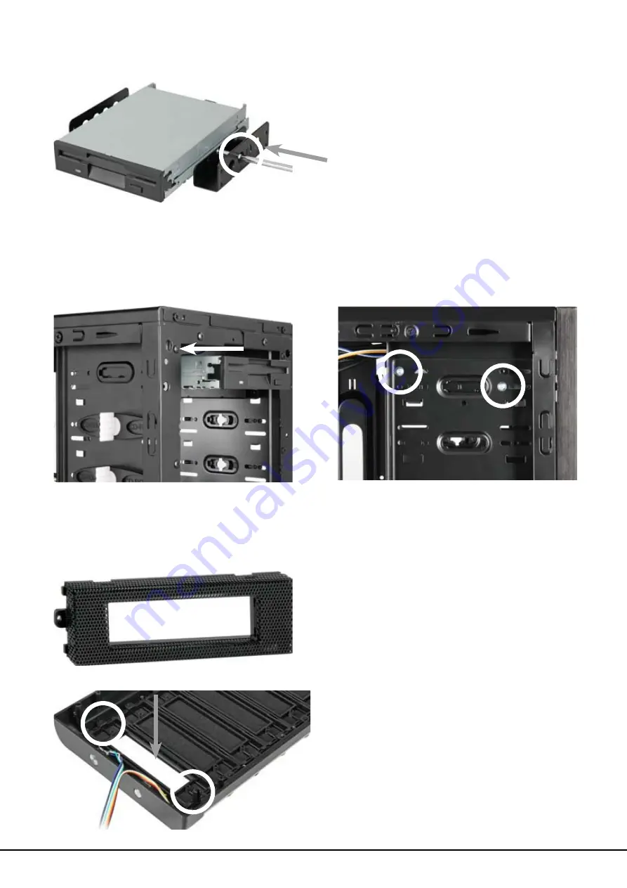
3. Screw the mounting angles to the 3.5" device from both sides (fig. 16).
fig. 16
4. Slide the 3.5" device with attached mounting rails into the case’s drive bay (fig. 17) and
screw it to the drive bay from both sides (fig. 18).
fig. 17 fig. 18
5. Connect the 3.5" device to the power supply and the mainboard.
6. Screw the 5.25" bezel with 3.5" opening into the front panel (fig. 19) and place it back onto
the case.
5.25" bezel with 3.5" opening
fig. 19


