Shark SC-2412A Operator'S Manual Download Page 20

SHARK SC-2412  •  97-6267  •  REV. 3/04

A

U

T

OMA

TIC P

A

R

TS  

W

ASHER    Maintenance  Guide

20

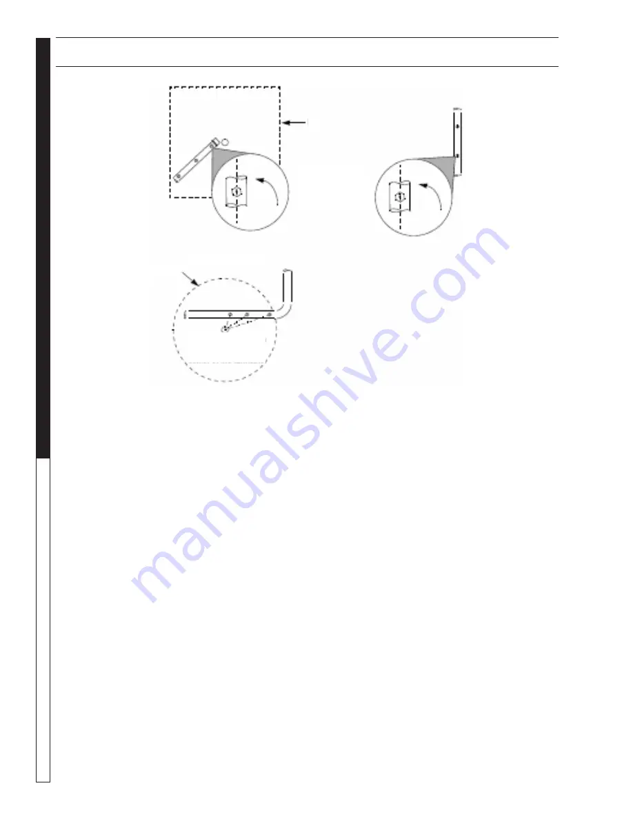
Cleaning and Aligning the Spray Nozzles

To ensure optimum cleaning performance, it is impor-
tant that you examine the spray nozzles periodically and
clean and align them if necessary.

To clean a plugged nozzle, remove it from the spray
pipe and use a small wire brush to free the nozzle of
any obstructions. When you replace the nozzle on the
spray pipe, make sure you align it according to Figure
Above to maintain a proper spray pattern.

Note: The spray nozzles are sized and positioned to
optimize the distribution of cleaning solution in the wash
chamber. If you remove the nozzles make sure you re-
place them in the correct position on the appropriate
pipe. Spray nozzle specifications are stamped on the
face of each nozzle, as shown above.

Cleaning out the Sump

Step 1:

Remove oil from the cleaning solution using the DOS
System (See 

Using the DOS System).

Step 2:

Remove the debris screen.

Step 3:

Drain the wash solution from the sump chamber. To drain
the solution either use the sump drain or a small sub-
mersible pump.

Section 5: Maintenance and Repair

TOP NOZZLES

SIDE NOZZLES

Align the notch in

each spray nozzle

with the center of the

turntable

Rotate each nozzle

approximately 3°

from the centerline of

the pipe

BOTTOM NOZZLES

Turntable

SIDE NOZZLES

Note:  Manufacturer recommends that you reuse the
wash solution. To do so, transfer it to a suitable holding
container (such as a 55-gallon drum) while you clean
out the sump chamber.

Step 4:

Remove sand and other debris from the bottom of the
sump chamber. To remove the debris either flush it out
through the sump drain, or vacuum it out using a wet/
dry vac. Dispose of the debris in accordance with appli-
cable local, state, and federal regulations.

Note: Take special care to ensure that the heating ele-
ment and the low-water float are free of debris. A build
up of debris around the heating element will decrease
heating performance and may cause the element to
overheat and fail. A build up of debris around the float
may cause the low water shut-off system to malfunc-
tion (See 

Low Water Shutoff System)

Step 5:

Transfer the wash solution back to the sump chamber,
and add fresh water if necessary.

Step 6:

Replace the debris screen.

Step 7:

Heat the wash water to operating temperature, then add
appropriate amount of factory detergent.

Step 8:

Run the machine through a 15-minute wash cycle.

Lid

Summary of Contents for SC-2412A

Page 1: ...SC AUTOMATIC PARTS WASHER For technical assistance or the SHARK dealer nearest you call 1 800 771 1881 or visit our website at www shark pw com SC 2412A SC 2412D 97 6267...

Page 2: ......

Page 3: ...the Machine with Water and Add Detergent 9 SECTION 3 Operation Main Operating Components 10 Control Panel 10 Thermostat 11 24 hour 7 day Heater Timer 11 Lid Safety Switch 11 Turntable Assembly 11 Deb...

Page 4: ...12 97 6267 REV 3 04 Washing Parts 19 Shutting Down the Machine 19 SECTION 4 Troubleshooting Overview 20 Troubleshooting the Electrical System 20 Testing Individual Components 20 SECTION 5 Maintenance...

Page 5: ...only operate on the type of elec trical power indicated on the electrical specifications tag Operating the machine on any other power sup ply will permanently damage the motors WARNING READ OPERATOR...

Page 6: ...ATION FRONT REAR Sump Drain Control Panel Lid Handle Optional Power Brush Optional Automatic Water Fill Assembly Power Cord Optional Detail Brush Pump Optional Air Flow Valve w Flow Regulator DOS Syst...

Page 7: ...12 97 6267 REV 3 04 7 AUTOMATIC PARTS WASHER OPERATOR S MANUAL COMPONENT IDENTIFICATION Spray Pipes and Nozzles Turntable Drive Arm Turntable Assembly w Optional Removable Containment Ring Optional De...

Page 8: ...s skip the following procedure Note To ensure proper operation and to minimize the possibility of premature component failure make sure the compressed air is supplied at 75 to 90 psi We also recommend...

Page 9: ...ater will reach operating temperature 160 180 F in approximately four hours To avoid having to wait for the wash solution to heat up before you use the machine each day install an op tional 24 hour 7...

Page 10: ...at See Ther mostat Note The machines contain an internal power relay that automatically disconnects power to the heater when the pump turns on the heater and pump cannot run simul taneously 120V only...

Page 11: ...either replace it or re install it See Previous Figure Debris Screen The debris screen is located below the turntable inside of the wash chamber See Figure Below The debris screen continuously filters...

Page 12: ...llowing Figure The detail brush uses a continuous flow of hot cleaning so lution through its nylon bristles to help you clean deli cate or lightly soiled parts The flow regulator controls the flow of...

Page 13: ...Fill The automatic water fill system automatically maintains a proper water level in the sump It is available as on option on these machines The automatic water fill system uses the low water shut of...

Page 14: ...n when loading and unloading the machine Step 1 Load large heavy parts directly onto the turntable Load small light parts in the optional small parts basket if available Make sure none of the parts ex...

Page 15: ...s e o d p m u p N O I T U L O S H S A W G N I T A E H T O N e s u f n w o l B o t r e f e R m e t s y S l a c i r t c e l E e h t g n i t o o h s e l b u o r T p m u s n i l e v e l r e t a w w o L f...

Page 16: ...t s u r h t n r o W y r a s s e c e n f i e c a l p e r g n i r a e b t s u r h t e h t t c e p s n I t e s y l r e p o r p m i r e t i m i l e u q r o T f i t s u j d a r e t i m i l e u q r o t e h...

Page 17: ...is connected Disconnect power to machine before removing fuses or other electrical components WARNING KEEP WATER SPRAY AWAY FROM ELECTRICALWIRING Troubleshooting the Electrical Panel None Power ON Pow...

Page 18: ...e the timer Heating Element Step 1 Disconnect power to the machine Step 2 Remove the rear panel from the machine ten screws use a 5 16 wrench or socket See Figure Below Step 3 Detach the power leads f...

Page 19: ...utes It is best to remove oil before you begin to use the machine each week To remove oil from the cleaning solution perform the following procedure Step 1 Check the water level indicator to ensure th...

Page 20: ...tenance and Repair TOP NOZZLES SIDE NOZZLES Align the notch in each spray nozzle with the center of the turntable Rotate each nozzle approximately 3 from the centerline of the pipe BOTTOM NOZZLES Turn...

Page 21: ...aling tape or compound on the threads to deter corrosion and be sure to install the rubber gasket to prevent leak Step 6 Install the new heating element Installation is the re verse of removal Thermos...

Page 22: ...dure Step 1 Raise the lid Section 5 Maintenance and Repair Low Water Indicator Heater and Turntable Switches Wash Cycle Timer Step 2 Loosen the torque limiter set screw use a 1 8 allen wrench See Figu...

Page 23: ...ow Step 4 Raise the lid Step 5 Loosen the retaining screw to remove the torque arm assembly from the drive shaft use a 1 8 allen wrench See Figure Below Step 6 Remove the three turntable mounting scre...

Page 24: ......

Page 25: ...Damage to components from fluctuations in electrical or water supply 5 Normal maintenance service including adjustments fuel system cleaning and clearing of obstructions 6 Transportation to service ce...

Page 26: ...Form 97 6267 Revised 3 04 Printed in U S A...

Reviews: