


8
WATER HEATER SERIES
OPERATOR’S MANUAL
97-6149 • 97-6162 • 97-6133 • Rev. 3/04
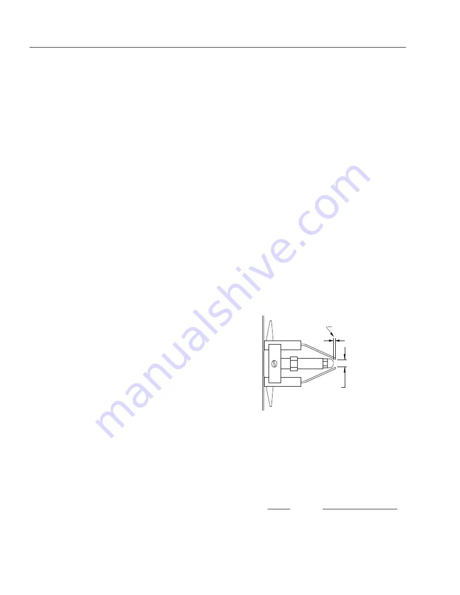
Gap
1/8"
3/16"
Side View
MAINTENANCE AND SERVICE
Winterizing Procedure:
Damage due to freezing is not covered by warranty. Ad-
here to the following cold weather procedures whenever
the washer must be stored or operated outdoors under
freezing conditions.
During winter months, when temperatures drop below
32°F, protecting your machine against freezing is nec-
essary. Store the machine in a heated room. If this is not
possible use compressed air on the short hose end. By
injecting compressed air, all water will be blown out of
the system. Run anti-freeze through the system.
Rupture Disk:
For safety, each machine is equipped with a rupture disk.
In the event the pressure of the water should exceed
8000 PSI, the rupture disk will release pressure and wa-
ter on to the ground.
When the disk ruptures, it will need to be replaced.
NOTE: Turn burner switch off. Then open spray gun to
cool heating coil or rupture disk will burst over time.
Adjustable Thermostat:
The adjustable thermostat can be set between 100°F to
225°F
(37.8° to 108°C). The temperature is dependent
on water flow and ambient water temperature.
Cleaning of Coils:
In alkaline water areas, lime deposits can accumulate
rapidly inside the coil pipes. This growth is increased by
the extreme heat build up in the coil. The best prevention
for liming conditions is to use high quality cleaning de-
tergents. In areas where alkaline water is an extreme
problem, periodic use of Deliming Powder will remove
lime and other deposits before coil becomes plugged.
Deliming Coils With A Pressure Washer:
Periodic flushing of coils or optional float tank is recom-
mended.
Step 1 Fill a 5 gallon bucket with 4 gallons of water,
then add 1 lb. of deliming powder. Mix thoroughly.
Step 2 Remove the high pressure nozzle from the pres-
sure wand and put the wand into the bucket.
Secure the trigger on the spray gun in the open
position.
Step 3 Attach a short section (3-5 ft.) of garden hose to
the attached pressure washer to siphon solu-
tion from the elevated bucket. Start up pressure
washer, allowing solution to be pumped through
pressure washer and into HP coils and back into
the bucket. Solution should be allowed to circu-
late 2-4 hours.
Step 4 After circulating solution flush entire system with
fresh water.
Removal of Soot In Heating Coil:
In the heating process fuel residue, in the form of soot
deposits, may develop between the heating coil pipes
and block air flow which affects burner combustion. When
soot has been detected on visual observation, the soot
on the coil must be cleaned off.
Fuel:
Use clean fuel oil that is not contaminated with water and
debris. Replace fuel filter and drain tank every 100 hours
of operation. Use Kerosene No. 1 or No. 2 Heating Fuel
(ASTM D306) or diesel only. NEVER use gasoline in your
burner tank. Gasoline is more combustible than fuel oil
and could result in a serious explosion. NEVER use crank-
case or waste oil in your burner. Fuel machine malfunc-
tion could result from contamination.
Ignition Circuit:
Periodically inspect wires, spring contact and electrodes
for condition, security and proper spacing. (CAUTION:
10,000 VOLTS)
Electrode Setting:
(See illustration below)
Electrodes Check : Periodically check wiring connections.
If necessary to adjust electrodes, use diagram.
Burner Nozzle:
Keep the tip free of surface deposits by wiping it with a
clean, solvent-saturated cloth, being careful not to plug
or enlarge the nozzle. For maximum efficiency, replace
the nozzle each season. Select nozzle size based on
the pressure washer you will be using:
Nozzle
Pressure Washer GPM
1.50
2 - 3
1.75
3 - 4
2.00 - 2.25
4 - 5
All nozzles should be 45° W


