background image

CALIBRATION

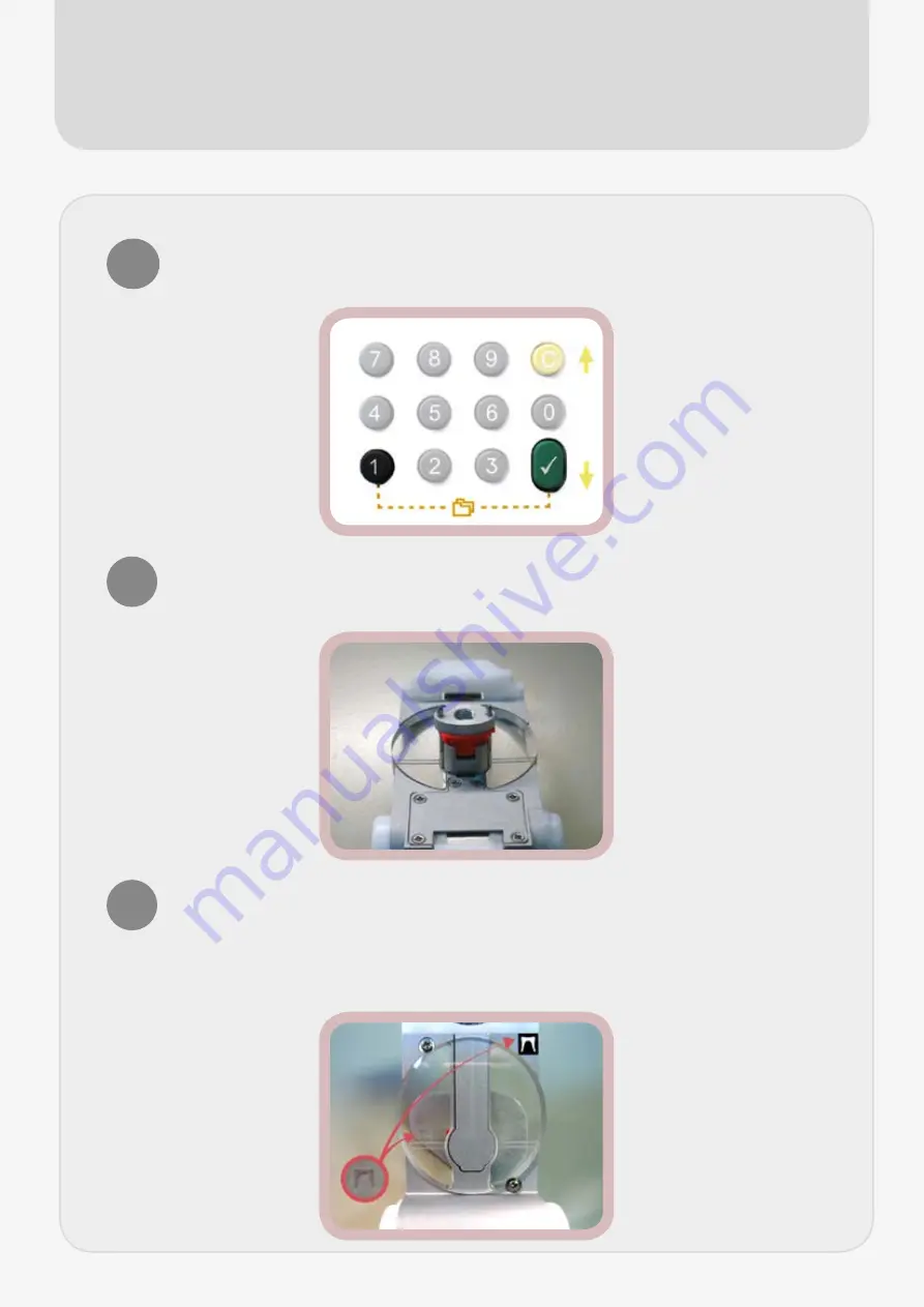
Press and hold the green ‘tick’ button in combination with the number 1. 

This will launch the menu. Press button 1 for calibration followed by the 

‘tick’ to confirm.

1

You will then be asked to load the first jig (G00001) which should be 

assembled by first placing the red plastic insert into the underside so 

that the pin falls into the hole on the insert.

2

Place the metal ‘eye’ pattern onto the pegs of the plastic insert so 

that the when viewing the jig from above the tiny engraved nose on 

the pattern can be seen and matches the orientation of the black nose 

sticker on the jig. Screw the metal thumb screw onto the bottom of the 

‘eye’ pattern plate. The jig should now be secure.

3

Summary of Contents for Star

Page 1: ...Quick Start User Guide ...

Page 2: ...SUPPLIED PARTS 1 x Right eye pattern plate 1 x Frame jig 1 x Rght eye pattern holding jig 2 x Narrow frame inserts 1 x Thumb screw 1 x Red plastic insert ...

Page 3: ... the plate outwards away from the side that is seated in the machine 2 Plug the RS232 cable into the middle of the three serial sockets on the back labeled RS232 The other end should be attached to your PC either directly or through the use of the supplied RS232 USB cable adaptor 3 Plug in the power cable and switch it on wait for the machine to boot before performing a full calibration See calibr...

Page 4: ...ith the vertical line at the back of the jaws Don t overdo the pressure or the frame may distort Frames with a narrow vertical measurement may benefit from the use of the small frame inserts 2 For a full rim ensure that the frame symbol is highlighted for both eyes D R G L The setting can be cycled by pressing the button repeatedly Press the big green go button to start tracing 3 FULL RIM ...

Page 5: ... and press down until it clicks into place 2 Press the frame symbol until right eye only is illuminated D R Note you must only use the right eye when uploading supras with our system Press the big green go button to start tracing 3 When a supra job has finished tracing the machine waits for you to enter the DBL before the shape is transferred to the computer Enter the number followed by the green ...

Page 6: ...assembled by first placing the red plastic insert into the underside so that the pin falls into the hole on the insert 2 Place the metal eye pattern onto the pegs of the plastic insert so that the when viewing the jig from above the tiny engraved nose on the pattern can be seen and matches the orientation of the black nose sticker on the jig Screw the metal thumb screw onto the bottom of the eye p...

Page 7: ...our tracer and numbered as such eg if it says on the screen M12485 your jig will have this number printed on it Insert the jig into the jaws and press the green tick to confirm that you ve done it followed by the big green go button to start tracing 5 After the second jig has finished tracing the machine will take a moment to calculate the data This normally takes a few minutes after which time th...

Page 8: ... go button This will set the trace going When finished the machine will either display Check OK or if the check fails Check KO 2 If the check is ok then you can begin tracing else a full calibration will be required 3 It may not always be necessary to perform a full calibration Usually a simple check will suffice and if it passes the calibration can optionally be skipped Note that it is still a go...

Reviews: