9
10
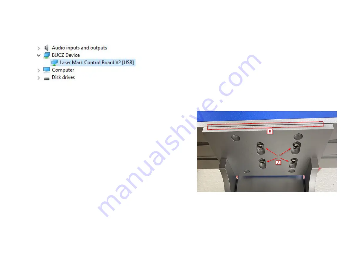
Once the driver is installed the Device Manager view will be updated
to show the Laser Control Board recognized by the system (Figure 5).
Figure 5
Software Setup (Ezcad)
“Installation” is not required to run Ezcad, it is a standalone program.
The best method is to copy the contents of the USB Thumb Drive
into a new folder on your desktop, and then create a shortcut to the
Ezcad executable. You can do this by locating the Ezcad executable,
right click and drag it onto the desktop. When you let go of the mouse
button a menu will appear, select “Create shortcut here”. Alternately
you can right click on the Ezcad executable and choose “Pin to
taskbar” to place it on your taskbar or “Pin to Start” to place it in the
Windows Start menu.
NOTE:
For Ezcad to operate in the Registered Mode the PC must be connected
to the laser with it powered on (the laser controller is the “Dongle”),
if the laser is not connected and powered up Ezcad can only be run in
trial mode which does not allow you to save any files from it.
Aligning the Emitter Head
As mentioned earlier in this document, the machine was shipped with
the emitter head moved forward over the working platform to save
space and protect it during shipping. It needs to be moved towards
the rear of the working platform to center the working area of the
emitter over the working platform. The following steps will help you
accomplish this.
1.Locate the center threaded hole in the working platform and insert
one of the M6 Allen head screws into it finger tight, this serves as an
easy reference to center of the working platform.
2.With the machine still powered up from the driver installation, open
the Ezcad application.
3.Place a shape in the working field within Ezcad and keep it selected,
this will cause the red drawing laser in the emitter head to light.
You will notice that it is far forward from the center of the working
platform.
4.On the underside of the emitter head assembly there are four (4)
Allen head screws (Figure 6 “A”).
Figure 6
5.Using the included Allen wrenches loosen these slightly, only
enough that you can slide the emitter assembly backwards.
6.Slide the emitter head backwards until the dot from the red tracing
laser is aligned with the center hole in the working platform on the X
axis.
Summary of Contents for SFX-GS
Page 2: ......


