background image

4

  │ 2 AQUAPHON system

AQUAPHON system

2.1 

General information regarding the system

In order to use the system for leak detection, a microphone must 

be connected to the A 50 receiver. The microphone picks up 

noises. 
If you press the Activation key on the receiver, you can hear the 

noises through the headphones. The playback volume is adjust-

able. The noises are not saved.

2.2 

Hearing protection

The system features a hearing protection function which protects 

the user from sudden loud sound interference. This type of sound 

interference can occur if a vehicle drives past or if the touch mi-

crophone slips off the contact point.
Hearing protection is activated when the predefined hearing pro

-

tection threshold is exceeded. When the noise from the source 

of interference ceases, hearing protection switches off again au

-

tomatically.
The way in which hearing protection works depends on the set-

tings (section 4.5 on page 23).

Note:

Another way of protecting the hearing from loud noises is to set 

the volume only as high as is absolutely necessary.

Summary of Contents for AQUAPHON A 50

Page 1: ...17 07 2017 a 107489 en AQUAPHON A 50 receiver Operating instructions...

Page 2: ...eceiver Arrow keys Up key Fig 1 A 50 receiver viewed from various angles Down key Activation key Display Filter key Menu key Enter key Belt clip Headphone socket Microphone socket Charging socket Conn...

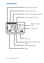
Page 3: ...ew Battery symbol for receiver Current noise level bar Current minimum noise level marker Current minimum noise level Minimum noise level last last but one Filter level Battery symbol for wireless hea...

Page 4: ...l injury Could result in injury or pose a risk to health NOTICE Risk of damage to property Note Tips and important information Numbered lists numbers letters are used for Instructions that must be fol...

Page 5: ...supply 10 2 3 3 Microphones 10 3 Using the system 13 3 1 Preparing the system 13 3 2 Switching on the system 13 3 2 1 A 50 receiver only 13 3 2 2 System with F8 wireless headphones 13 3 2 3 System wit...

Page 6: ...ve battery 30 5 4 2 2 Removing the battery from the A 50 receiver 30 6 Appendix 32 6 1 Technical data 32 6 1 1 A 50 receiver 32 6 1 2 TS 50 test rod 34 6 1 3 UM 50 universal microphone 35 6 2 Micropho...

Page 7: ...y be used when performing repairs Changes or modifications to this product may only be carried out with the approval of Hermann Sewerin GmbH Use only Hermann Sewerin GmbH accessories for the product H...

Page 8: ...urfaces e g gravel crushed rock grass Note The descriptions in these operating instructions relate to the sys tem as delivered factory settings The manufacturer reserves the right to make changes 1 3...

Page 9: ...wing safety information without fail Risk of personal injury health risk Handle the components carefully and safely both during trans port and when working Proceed with extreme caution in the vicinity...

Page 10: ...ng protection function which protects the user from sudden loud sound interference This type of sound interference can occur if a vehicle drives past or if the touch mi crophone slips off the contact...

Page 11: ...nes wired Microphones UM 50 universal microphone TS 50 test rod The microphones have to be used in conjunction with acces sories Accessories Probe tips and extensions available in various lengths M 10...

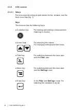
Page 12: ...ing keys Activation key For starting and ending a measurement listening to noises Arrow keys For adjusting the volume For changing settings and filter limits Filter key For switching between the main...

Page 13: ...Display rotation The orientation of the display can be adjusted to the position in which the receiver is used If the receiver is rotated through 180 about its longitudinal axis the display rotates too...

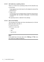
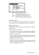
Page 14: ...ressed briefly to start the measurement The Activation key is pressed briefly again to end the meas urement The operating mode is selected in the settings 2 3 2 4 Noise level display The following noi...

Page 15: ...of a black bar Minimum noise level The minimum noise level relates to an ongoing or completed measurement Current minimum noise level The current minimum noise level is displayed in the middle of the...

Page 16: ...explode due to internal short circuit Components containing a faulty lithium ion battery must not be shipped Information about charging the rechargeable battery can be found in section 5 1 on page 27...

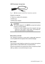
Page 17: ...ct adapter away from magnetic storage media e g hard drives credit cards and medical de vices e g pacemakers insulin pumps Microphone protector The universal microphone comes with a rubberised protect...

Page 18: ...RP 10 resonance plate optionally with M 10 tripod Safety information about handling the TS 50 Handle the test rod carefully and safely both during transport and when working Exercise particular cauti...

Page 19: ...over supplied 3 2 Switching on the system How the system is switched on depends on which headphones are used 3 2 1 A 50 receiver only The A 50 receiver switches on automatically as soon as a micro pho...

Page 20: ...K3 headphones When using the K3 headphones the system is switched on as follows 1 The K3 headphones must be used with the 3 5 mm phone jack Remove the adapter 6 3 mm from the phone jack if necessary 2...

Page 21: ...n key How the Activation key is used depends on the selected oper ating mode Information about the operating modes can be found in sec tion 2 3 2 3 on page 8 The system is ready for use The display sh...

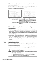
Page 22: ...ing protection threshold has been exceeded during the measurement As soon as the noise level falls below the hearing protection threshold again the symbol appears without a cross through it No measure...

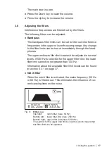
Page 23: ...wer filter limit can each be adjusted in several levels If 500 Hz is selected for the upper filter limit the lower filter limit cannot be set greater than 120 Hz Information about the available filter...

Page 24: ...nter key until the symbol in front of the filter you wish to change is inverted b For the filter limits Press the Up key to increase the value Press the Down key to lower the value For the notch filte...

Page 25: ...type of hearing protection and the hearing protection threshold can be configured individually The individual settings are saved until the next change The fac tory settings can be restored at any tim...

Page 26: ...system is ready for use The display shows the main view 1 Press the Menu key The Settings view appears 2 Keep pressing the Enter key until LIGHT is inverted 3 Change the setting Press the Down key to...

Page 27: ...2 3 on page 8 Changing the ACTIVATION setting The system is ready for use The display shows the main view 1 Press the Menu key The Settings view appears 2 Keep pressing the Enter key until ACTIVATION...

Page 28: ...ctivated Changing the DISPLAY setting The system is ready for use The display shows the main view 1 Press the Menu key The Settings view appears 2 Keep pressing the Enter key until DISPLAY is inverted...

Page 29: ...not listen to noise Changing the MUTE settings The system is ready for use The display shows the main view 1 Press the Menu key The Settings view appears 2 Keep pressing the Enter key until MUTE is in...

Page 30: ...is the volume limit above which hearing protection is activated Hearing protection threshold here level 4 The hearing protection threshold can be set to four levels Level Display Hearing protection t...

Page 31: ...n threshold to the current situation Choose as low as possible a hearing protection thresh old The system is ready for use The display shows the main view 1 Press the Menu key The Settings view appear...

Page 32: ...the factory settings can be found in section 6 3 2 on page 38 Restoring settings to factory settings Note The settings are reset immediately and with no further warning The system is ready for use Th...

Page 33: ...use The battery in the A 50 receiver can discharge self discharge even when the receiver is not in use You should charge the battery at least once every 6 months Fig 11 Display when charging Left hand...

Page 34: ...structions 5 2 Care To care for the components simply wipe them down with a damp cloth NOTICE Risk of damage The display surface of the A 50 receiver is sensitive to mechan ical and chemical stress Al...

Page 35: ...oses The transport of defective lithium ion batteries is restricted e g air freight is not permissible Where transport is permitted e g by road or rail it is subject to strict regulations Therefore a...

Page 36: ...ive3 Housing damaged or badly deformed Liquid leaking from battery Smell of gas from battery Rise in temperature with the receiver switched off more than hand hot Plastic parts melted or deformed Conn...

Page 37: ...from the power supply by unplugging the white connector on the circuit board Do not under any circumstances rip out the cable 4 The battery is fixed in place in the bottom section of the hous ing by...

Page 38: ...icate Certificate with SDR FCC CE IC MIC without SDR FCC CE Device elements Display 2 FSTN display 240 128 pixels LED backlight Processor 16 bit digital signal processor Control Membrane keypad 1 acti...

Page 39: ...0 2000 3000 4000 5000 8000 Hz Notch filter 50 60 Hz off Sampling rate 16 bit 48 kHz Indication range 0 999 digits Data transmission Transmission frequency 2 408 2 476 GHz 38 channels Radio range 2 m T...

Page 40: ...g conditions Operating temperature 20 C 70 C Storage temperature 20 C 70 C Humidity 100 r h Protection rating IP65 Permitted operating envi ronments outdoors in building Non permitted operating enviro...

Page 41: ...Operating temperature 20 C 70 C Storage temperature 20 C 70 C Protection rating IP68 Permitted operating envi ronments outdoors in building Non permitted operating environments in aggressive media in...

Page 42: ...Configuration Preliminary detection Fitting UM 50 Probe tip optional extensions TS 50 Probe tip optional extensions Magnetic UM 50 M 10 contact adapter Pinpointing leaks Paved TS 50 RP 10 Paved Unpave...

Page 43: ...lter limit upper filter limit 0 Hz 500 Hz 30 Hz 850 Hz 60 Hz 2000 Hz 120 Hz 3000 Hz 250 Hz 4000 Hz 500 Hz 5000 Hz 8000 Hz If 500 Hz is selected for the upper filter limit the lower filter limit cannot...

Page 44: ...t activated Hold mode Display rotation activated Do not listen to noise Hearing protection threshold Level 4 Bandpass lower filter limit upper filter limit 0 Hz 4000 Hz Notch filter Symbol Notch filte...

Page 45: ...mm 4000 1213 Probe tip extension M10 300 mm 4000 1216 Probe tip extension M10 600 mm 4000 1215 EM 20 contact adapter EM20 Z1000 RP 10 resonance plate EA16 Z1000 M 10 tripod 4000 0966 AC DC adapter M4...

Page 46: ...f the following Directive 2014 53 EU The complete declarations of conformity can be found online 6 6 Advice on disposal The European Waste Catalogue EWC governs the disposal of appliances and accessor...

Page 47: ...actory settings 26 38 Filter key 6 H Headphone socket 7 Hearing protection 4 23 Hearing protection threshold 24 levels 24 Hold mode 8 L LIGHT 20 Listening to noises 15 Lithium ion rechargeable battery...

Page 48: ...g protection 23 hearing protection threshold 24 operating mode 21 System components overview 5 preparing 13 switching off 15 switching on 13 with F8 wireless headphones 13 with K3 headphones 14 T Togg...

Page 49: ...w sewerin fr sewerin sewerin fr Sewerin Ltd Hertfordshire UK Phone 44 1462 634363 www sewerin co uk info sewerin co uk SEWERIN IBERIA S L Centro de Negocios Eisenhower Avenida Sur del Aeropuerto de Ba...

Reviews: