background image

4

Mechanical installation

Installation requirements

Operating Instructions – WOP11D-70-0, WOP11D-100-0 and WOP11D-150-0

22

Wiring connections

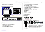
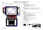
To make wiring connections to the power supply connector, follow the table with cable
and torque specifications below:

Terminal Block Con-
nector

Wire Size AWG

Torque (Lb. ln.)

X1/X100 Phoenix connect-
ors

AWG 30 – 12

5 – 7

X1/X100 Anytek connect-
ors

AWG 24 – 12

3.5

X1/X100 DECA connectors AWG 24 – 12

7

Usage

These devices are Class 2 supplied programmable controllers (industrial PCs) for the
use in industrial control equipment and are intended to be (front) panel mounted (type
12 and 4X for indoor use only).

International protection

The enclosure provides a degree of protection of at least IP20, but when installed in
an apparatus, it should meet IP65.

4.3

Installation requirements

Check that the following conditions have been met:

The information on the nameplate of the device corresponds to the line voltage.

The device is undamaged (no damage caused by transport or storage).

The ambient temperature corresponds to the specification in the operating instruc-
tions and the nameplate of the device.

26860481/EN – 03/2021

Summary of Contents for WOP11D-100-0

Page 1: ... 26860481_0321 Drive Technology Drive Automation System Integration Services Operating Instructions Web Operator Panels WOP11D 70 0 WOP11D 100 0 and WOP11D 150 0 Edition 03 2021 26860481 EN ...

Page 2: ...SEW EURODRIVE Driving the world ...

Page 3: ... 2 5 Functional safety technology 11 2 6 Transportation storage 11 2 7 Setup installation 11 2 8 Electrical connection 12 2 8 1 ESD protection measures 12 2 8 2 Electromagnetic compatibility EMC 12 2 9 Startup and operation 12 2 10 Service maintenance 12 3 Device structure 13 3 1 Basic device 13 3 1 1 Web operator panel WOP11D 70 0 13 3 1 2 Web operator panel WOP11D 100 0 14 3 1 3 Web operator pan...

Page 4: ...panels WOP11D 70 0 and WOP11D 100 0 32 5 2 2 Web operator panel WOP11D 150 0 33 5 3 Grounding 34 5 3 1 Web operator panels WOP11D 70 0 and WOP11D 100 0 34 5 3 2 Web operator panel WOP11D 150 0 34 5 4 Connecting a voltage supply 35 5 4 1 Web operator panels WOP11D 70 0 and WOP11D 100 0 36 5 4 2 Web operator panel WOP11D 150 0 36 5 4 3 Using the 24 V supply connector with AC DC power supply unit 37 ...

Page 5: ... 8 Approvals 45 10 2 Pin assignment 46 10 2 1 Web operator panels WOP11D 70 0 and WOP11D 100 0 46 10 2 2 Web operator panel WOP11D 150 0 47 10 3 Dimension drawings 50 10 3 1 Web operator panel WOP11D 70 0 50 10 3 2 Web operator panel WOP11D 100 0 51 10 3 3 Web operator panel WOP11D 150 0 52 Index 54 26860481 EN 03 2021 ...

Page 6: ...erstood it If you are unclear about any of the information in this documentation or if you require further information contact SEW EURODRIVE 1 2 Other applicable documentation Observe the corresponding documentation for all additional components 1 3 Structure of the safety notes 1 3 1 Meaning of signal words The following table shows the grading and meaning of the signal words for safety notes Sig...

Page 7: ...3 Structure of embedded safety notes Embedded safety notes are directly integrated into the instructions just before the de scription of the dangerous action This is the formal structure of an embedded safety note SIGNAL WORD Type and source of hazard Possible consequence s if disregar ded Measure s to prevent the hazard 1 4 Decimal separator in numerical values In this document a period is used t...

Page 8: ...WOP11D 70 0 WOP11D 100 0 and WOP11D 150 0 8 1 7 Copyright notice 2021 SEW EURODRIVE All rights reserved Unauthorized reproduction modifica tion distribution or any other use of the whole or any part of this documentation is strictly prohibited 26860481 EN 03 2021 ...

Page 9: ...ser you must ensure that all of the work listed in the following may be carried out only by qualified specialists Setup and installation Installation and connection Startup Maintenance and repairs Shutdown Disassembly Ensure that the persons who work on the product pay attention to the following regula tions conditions documentation and information National and regional safety and accident prevent...

Page 10: ... with electrical installation startup troubleshooting and main tenance of the product who possess the following qualifications Qualifications in the field of electrical engineering in accordance with the national regulations Familiarity with this documentation Additional qualific ations In addition to that these persons must be familiar with the valid safety regulations and laws as well as with th...

Page 11: ... any safety functions without a higher level safety sys tem unless explicitly allowed by the documentation 2 6 Transportation storage Inspect the shipment for damage as soon as you receive the delivery Inform the ship ping company immediately about any damage If the product is damaged it must not be assembled installed or started up If necessary use suitable sufficiently dimensioned handling equip...

Page 12: ... all persons in ESD protection areas without ESD protection clothing do not touch components or printed circuit boards Visitors must be informed of the regulations in force Printed board assemblies may only be transported using the plug in systems or trays designed for this purpose Printed circuit boards may only be dispatched in ESD pack aging material 2 8 2 Electromagnetic compatibility EMC The ...

Page 13: ...0 0 The following figure shows the front and rear of the device 4 5 6 7 8 1 2 11 3 10 9 A B 33861004811 A Front B Rear 1 Screen 2 Glass front 3 Galvanized sheet metal 4 Mounting element with screw 5 Gasket 6 Ethernet interface 2 46 7 2 USB interfaces 2 46 8 DC 24 V voltage supply 2 46 9 Grounding lug 10 Slot for micro SD memory card 11 Basic module 26860481 EN 03 2021 ...

Page 14: ... figure shows the front and rear of the device 4 5 6 7 8 1 2 10 9 11 3 A B 33956280715 A Front B Rear 1 Screen 2 Glass front 3 Galvanized sheet metal 4 Mounting element with screw 5 Gasket 6 Ethernet interface 2 46 7 2 USB interfaces 2 46 8 DC 24 V voltage supply 2 46 9 Grounding lug 10 Slot for micro SD memory card 11 Basic module 26860481 EN 03 2021 ...

Page 15: ... 1 3 Web operator panel WOP11D 150 0 The following figure shows the front and rear of the device 3 4 1 2 8 6 7 5 A B 33967307531 A Front B Rear 1 Screen 2 Glass front 3 Mounting element with screw 4 Gasket 5 Connections 2 33 6 Control panel for screen 2 39 7 PE screw 8 Basic module 26860481 EN 03 2021 ...

Page 16: ...OP11D 70 0 Type WOP Web Operator Panel Built in variant 11 Control cabinet Generation D Size 70 70 TFT LCD display with 7 inch screen diagonal 1024 600 pixels 16700000 colors 100 TFT LCD display with 10 1 inch screen diagonal 1280 800 pixels 16700000 colors 150 TFT LCD display with 15 6 inch screen diagonal 1920 1080 pixels 16200000 colors Design 0 Standard INFORMATION For further information on w...

Page 17: ...al interface 3 3 3 Processor board The processor board is designed as a single board and contains all interfaces avail able on the operator panel Standard features include eMMC memory a serial NOR flash for fast booting and a DDR4 DRAM internal memory All components are hard soldered to ensure high reli ability 3 3 4 Micro SD memory card INFORMATION The slot for the micro SD memory card is only av...

Page 18: ...ernet connection RJ45 socket No LED Behavior Meaning 1 2 1 10 100 1000 Mbit Off 10 Mbit Lights up green 100 Mbit Lights up orange 1000 Mbit 2 Activity Link Off There is no Ethernet connection Lights up yellow There is an Ethernet connection to an other Ethernet station Flashes yellow Data is currently being exchanged via Ethernet 3 3 7 USB interfaces The USB interface version depends on the device...

Page 19: ...ing elements 12 screws M4 TX20 24 V supply connector 3 5 Accessories INFORMATION The delivery does not include accessories such as 24 V voltage supply and connec tion cables If you are not sure which accessories you need employees at SEW EURODRIVE will be happy to help you make the right selection Accessories Part number Switched mode power supply with 2 5 A1 01881817 1 Only applies to operator pa...

Page 20: ... personal injury and damage to property Adhere to the notes about installation and disassembly Do not install the device alone at least 2 persons Make sure that the thickness of the mounting plate is 3 7 mm NOTICE Risk of damage due to improper installation Damage to property Use only the retaining clamps and screws M4 12 included in the delivery for installation To fasten the screws properly use ...

Page 21: ...l authority having jurisdiction at the time of installation All devices have to be supplied by a Class 2 power supply Expansion units Only UL and cUL approved expansion units are allowed to be connected to the port designated EXPANSION At the moment there are no such units evaluated or al lowed Battery Battery may explode if mistreated Do not recharge disassemble or dispose of in fire This product...

Page 22: ... programmable controllers industrial PCs for the use in industrial control equipment and are intended to be front panel mounted type 12 and 4X for indoor use only International protection The enclosure provides a degree of protection of at least IP20 but when installed in an apparatus it should meet IP65 4 3 Installation requirements Check that the following conditions have been met The informatio...

Page 23: ...the required space into account The following figures show the required space for installing the device 4 4 1 Web operator panels WOP11D 70 0 and WOP11D 100 0 100 50 50 100 100 33963632139 All dimensions are specified in mm 4 4 2 Web operator panel WOP11D 150 0 100 50 50 100 100 33882503307 All dimensions are specified in mm 26860481 EN 03 2021 ...

Page 24: ...ng while it is not being used for operational purposes unless it is otherwise protected Unpack or pack the device only at safe EOS ESD workplaces If a safe workplace cannot be guaranteed it is important that the user is electrically discharged before the equipment comes into direct contact with the body or with tools The body can be easily discharged by touching a grounded metal part e g the syste...

Page 25: ...red ü The mounting elements with screws included in the delivery are ready for use 1 Make sure that the seal of the operator panel is seated evenly and without deform ation 2 Place the operator panel from the front into the cut out of the mounting plate and push it carefully up to the stop 3 Insert the mounting elements into the T shaped cut outs provided on the back of the operator panel 4 Push t...

Page 26: ...ent on one corner of the operator panel tighten the screw clockwise with a tightening torque of 0 2 Nm until it presses on the mounting plate 33963710091 6 Repeat this procedure first for the crosswise opposite mounting element and only then for the remaining mounting elements 33963714059 ð The operator panel is now mounted 26860481 EN 03 2021 ...

Page 27: ...ng elements with screws included in the delivery are ready for use 1 Make sure that the seal of the operator panel is seated evenly and without deform ation 2 Place the operator panel from the front into the cut out of the mounting plate and push it carefully up to the stop 3 Pivot the mounting elements on the back of the operator panel so that the screws are above the mounting plate 33969355403 2...

Page 28: ...g element on one corner of the operator panel tighten the screw clockwise with a tightening torque of 0 2 Nm until it presses on the mounting plate 5 Repeat this procedure first for the crosswise opposite mounting element and only then for the remaining mounting elements 33969359755 ð The operator panel is now mounted 26860481 EN 03 2021 ...

Page 29: ... screws included in the delivery are ready for use 1 Make sure that the seal of the operator panel is seated evenly and without deform ation 2 Insert the screws into the mounting elements 33882793995 3 Place the operator panel from the front into the cut out of the mounting plate and push it carefully up to the stop 4 Place the mounting element with the screw into the housing of the operator panel...

Page 30: ... 100 0 and WOP11D 150 0 30 5 Tighten the screw clockwise with a tightening torque of 0 8 Nm 0 2 Nm until the mounting element is pressed against the housing wall 33869333387 6 Repeat the procedure for the remaining screws 33869337355 ð The operator panel is now mounted 26860481 EN 03 2021 ...

Page 31: ...onnector included in the delivery for a connection to the in put current connection of the device Check the electrical specification on the nameplate of the device NOTICE Risk of damage when disconnecting or connecting voltage carrying plug connectors Possible damage to property Switch off the line voltage Never plug or unplug plug connectors while they are energized NOTICE Risk of damage to conne...

Page 32: ...Socket for DC 24 V voltage supply 2 46 pluggable terminal socket 3 pin 2 X9 USB interface 2 USB host 2 0 type A 2 46 3 X5 Ethernet interface NET1 1 10 100 1000 Mbit 2 46 shielded RJ45 IP address 192 168 1 100 The following figures show the connection options on the side of the device Web operator panel WOP11D 70 0 2 1 33963516043 Web operator panel WOP11D 100 0 1 2 34064676875 1 X3 Card slot for m...

Page 33: ...e for PC connection 2 49 3 HDMI interface for PC connection 2 48 4 Ethernet interface LAN 2 1 10 100 1000 Mbit shielded RJ45 2 47 IP address 192 168 10 10 5 Ethernet interface LAN 1 1 10 100 1000 Mbit shielded RJ45 2 47 IP address 192 168 1 99 6 USB interface 1 USB host 3 0 type A 2 48 7 USB interface 2 USB host 2 0 type A 2 47 8 X3 Connection for DC 24 V voltage supply 2 47 9 X2 not assigned 10 X...

Page 34: ... unplugging plug connectors or connecting test devices Keep the work area free of non conductive materials such as common plastic and styrofoam assembly aids For field service use tools such as cutters screwdrivers and vacuum cleaners that are conductive Always place drives and circuit boards on the foam with the printed circuit board side down 5 3 1 Web operator panels WOP11D 70 0 and WOP11D 100 ...

Page 35: ... Possible damage to property Connect the device only to a voltage supply that provides the specified input power and meets the protective extra low voltage SELV and limited current source LPS requirements pursuant to UL IEC 60950 1 or PS2 pursuant to UL IEC 62368 1 Use the 24 V supply connector included in the delivery for connection to the input current socket of the device Check the electrical s...

Page 36: ... of the voltage supply 1 2 3 34182424715 Terminal socket No Signal Description X1 1 FE Functional earth 2 GND Reference potential 3 24V DC 24 V voltage supply 20 5 4 2 Web operator panel WOP11D 150 0 The following figure shows the connection of the voltage supply 2 1 3 33872158859 Terminal socket No Signal Description X3 1 GND Reference potential 2 FE Functional earth 3 24V DC 24 V voltage supply ...

Page 37: ... the 24 V supply connector included in the delivery to the AC DC power supply unit for example the switched mode power supply UWU52A from SEW EURODRIVE 3 Plug the 24 V supply connector into the following terminal socket ð Terminal socket X1 of the WOP11D 70 100 0 operator panel ð Terminal socket X3 of the WOP11D 150 0 operator panel 4 Connect a power supply cable to the power socket that meets reg...

Page 38: ...or panel via Ethernet The clear menu structure allows for quickly finding the numerous setting options such as network settings URL display FTP IP tables screensaver web browser settings passwords diagnostics and others A detailed description of the setting options and functions can be found in the software manual for WOP11D 70 0 WOP11D 100 0 and WOP11D 150 0 operator panels part number 26860457 6...

Page 39: ...of the operator panel 1 2 3 34084373131 No Button LED Behavior Meaning 1 Power button The button is pressed when the device is switched on The device is switched to standby mode The button is pressed when the Power LED flashes green The device is switched back on again after standby mode The button is pressed when the device is shut down The device is restarted 2 Power LED Off The device is switch...

Page 40: ...e grounding is connected correctly 8 2 Waste disposal Dispose of the product and all parts separately in accordance with their material struc ture and the national regulations Put the product through a recycling process or con tact a specialist waste disposal company If possible divide the product into the follow ing categories Iron steel or cast iron Stainless steel Magnets Aluminum Copper Electr...

Page 41: ...ispose of the product and its accessories according to the national regulations of your country For further information contact the responsible SEW EURODRIVE branch or an au thorized partner of SEW EURODRIVE Waste disposal according to the Battery Directive 2006 66 EC This product contains batteries or accumulators Dispose this product and the batter ies or accumulators separately from the municip...

Page 42: ... no liquid comes into contact with other parts of the housing NOTICE Dirt particles can scratch the surface of the screen Do not apply pressure when cleaning the screen Do not use corrosive cleaners abrasive cleaners or hard objects that may scratch the screen display Before cleaning switch off the operator panel because the screen display is safe to touch To remove dust and dirt particles clean t...

Page 43: ...250 mm Installation depth installa tion depth including clear ance 42 5 mm 142 5 mm 35 5 mm 135 5 mm 70 mm 170 mm Weight Approx 0 83 kg Approx 1 26 kg Approx 6 5 kg Cooling Passive cooling no fan Protective material of rear side Stainless steel Steel zinc plated Protective material of frame Aluminum Anodized aluminum Protective material of glass front Glass chemically tempered Degree of protection...

Page 44: ...on the configuration and the type and number of active interfaces Recommended dimension ing of the power supply unit voltage output power DC 24 V min 30 W 50 W 10 1 5 Power supply cable Power supply cable Connector type Phoenix MSTBA 2 5 3 G 24 V supply connector Phoenix FKCN 2 5 3 ST Cable length max 3 m unshielded Cable cross section min 0 5 mm2 max 1 5 mm2 Stripping length 10 mm 10 1 6 Communic...

Page 45: ... to h 3000 m Humidity 10 90 non condensing Atmosphere Free from corrosive or explosive gases 10 1 8 Approvals WOP11D 70 0 WOP11D 100 0 WOP11D 150 0 Low Voltage Directive 2014 35 EU EMC Directive 2014 30 EU EMC tests on the device EN 61000 6 2 interference immunity EN 61000 6 4 emission EN 61000 6 2 interference immunity EN 55032 emission RoHS II Directives 2011 65 EU 2011 65 EU 2015 863 EU 2017 21...

Page 46: ...nt 10 2 1 Web operator panels WOP11D 70 0 and WOP11D 100 0 X1 DC 24 V voltage supply Terminal socket 3 pin No Signal 1 2 3 1 FE 2 GND 3 24V X5 Ethernet interface RJ45 socket No Signal 1 8 1 TX0 2 TX0 3 TX1 4 TX2 5 TX2 6 TX1 7 TX3 8 TX3 X9 USB interface 2 0 type A USB socket No Signal 1 4 1 USB_VCC 2 USB_D 3 USB_D 4 GND 26860481 EN 03 2021 ...

Page 47: ...TX2 6 TX1 7 TX3 8 TX3 LEDs LEDs in the RJ45 socket indicate the status of the Ethernet connection RJ45 socket No LED Behavior Meaning 1 2 1 10 100 1000 Mbit Off 10 Mbit Lights up green 100 Mbit Lights up orange 1000 Mbit 2 Activity Link Off There is no Ethernet connec tion Lights up yellow There is an Ethernet connection to another Ethernet station Flashes yellow Data is currently being ex changed...

Page 48: ...l 1 4 9 5 1 USB_VCC 2 USB_D 3 USB_D 4 GND 5 USB_RX 6 USB_RX 7 GND 8 USB_TX 9 USB_TX HDMI interface HDMI socket No Signal 18 2 19 1 1 TMDS Data2 2 GND 3 TMDS Data2 4 TMDS Data1 5 GND 6 TMDS Data1 7 TMDS Data0 8 GND 9 TMDS Data0 10 TMDS Clock 11 GND 12 TMDS Clock 13 Reserved 14 Reserved 15 DDC_CLK 16 DDC_DATA 17 GND 18 5 V Power 19 Hot Plug Detect 26860481 EN 03 2021 ...

Page 49: ...ating Instructions WOP11D 70 0 WOP11D 100 0 and WOP11D 150 0 49 VGA interface VGA socket No Signal 9 15 1 8 1 Red 2 Green 3 Blue 4 Not assigned 5 GND 6 GND 7 GND 8 GND 9 VCC 10 GND 11 Not assigned 12 DDC Data 13 Hsync 14 Vsync 15 DDC Clock 26860481 EN 03 2021 ...

Page 50: ...11D 70 0 Device 76 6 76 6 16 2 30 7 76 6 76 6 30 7 16 2 66 66 200 1 210 5 131 9 142 3 16 163 5 188 7 5 7 5 39 7 42 4 42 78 0 5 16 33989278475 All dimensions are specified in mm Cut out for installation 189 7 121 5 34103581707 All dimensions are specified in mm Width Height Installation depth Thickness of mounting plate 189 7 mm 121 5 mm Approx 42 5 mm 3 7 mm 26860481 EN 03 2021 ...

Page 51: ... 0 Device 5 5 32 7 35 4 9 172 3 78 29 5 64 8 264 5 187 79 79 80 13 3 13 3 80 9 80 9 11 3 14 238 9 250 5 163 5 7 161 8 33989282443 All dimensions are specified in mm Cut out for installation 252 174 5 34103585675 All dimensions are specified in mm Width Height Installation depth Thickness of mounting plate 252 mm 174 5 mm Approx 35 5 mm 3 7 mm 26860481 EN 03 2021 ...

Page 52: ...Instructions WOP11D 70 0 WOP11D 100 0 and WOP11D 150 0 52 10 3 3 Web operator panel WOP11D 150 0 Device 399 411 387 399 65 29 5 105 65 29 5 105 28 67 134 63 67 63 67 85 69 1 260 13 7 6 6 6 272 198 50 6 6 34103561867 All dimensions are specified in mm 26860481 EN 03 2021 ...

Page 53: ...perating Instructions WOP11D 70 0 WOP11D 100 0 and WOP11D 150 0 53 Cut out for installation 389 250 33883737355 All dimensions are specified in mm Width Height Installation depth Thickness of mounting plate 389 mm 250 mm Approx 70 mm 3 7 mm 26860481 EN 03 2021 ...

Page 54: ...0 0 50 Device structure Web operator panel WOP11D 100 0 14 Web operator panel WOP11D 150 0 15 Web operator panel WOP11D 70 0 13 Dimension drawing of cut out Web operator panel WOP11D 100 0 51 Web operator panel WOP11D 150 0 53 Web operator panel WOP11D 70 0 50 E Electrical connection 12 Electrical installation 31 Electromagnetic compatibility 12 Embedded safety notes 7 EMC Directive 45 ESD protect...

Page 55: ... interface 48 USB interface 2 0 46 47 USB interface 3 0 48 VGA interface 49 Processor board 17 Product names 7 R Rights to claim under limited warranty 7 RoHS II Directives 45 S Safety functions 11 Safety Notes Designation in the documentation 6 Meaning of the hazard symbols 7 Operation 12 Preliminary information 9 Service maintenance 12 Startup 12 Structure of embedded 7 Structure of section rela...

Page 56: ... V supply connector 37 Web operator panel WOP11D 100 0 36 Web operator panel WOP11D 150 0 36 Web operator panel WOP11D 70 0 36 W Waste disposal 40 Web operator panel WOP11D 100 0 Connections 32 Device structure 14 Web operator panel WOP11D 150 0 15 Connections 33 Device structure 15 Web operator panel WOP11D 70 0 Connections 32 Device structure 13 26860481 EN 03 21 Operating Instructions WOP11D 70...

Page 57: ......

Page 58: ......

Page 59: ......

Page 60: ...SEW EURODRIVE Driving the world SEW EURODRIVE GmbH Co KG Ernst Blickle Str 42 76646 BRUCHSAL GERMANY Tel 49 7251 75 0 Fax 49 7251 75 1970 sew sew eurodrive com www sew eurodrive com ...

Reviews: