SEW-Eurodrive MOVI-PLC advanced Manual Download Page 21

Manual – MOVI-PLC® advanced Controller Remote Maintenance via ORA11B  

21

Configuration of ORA11B

Configuration

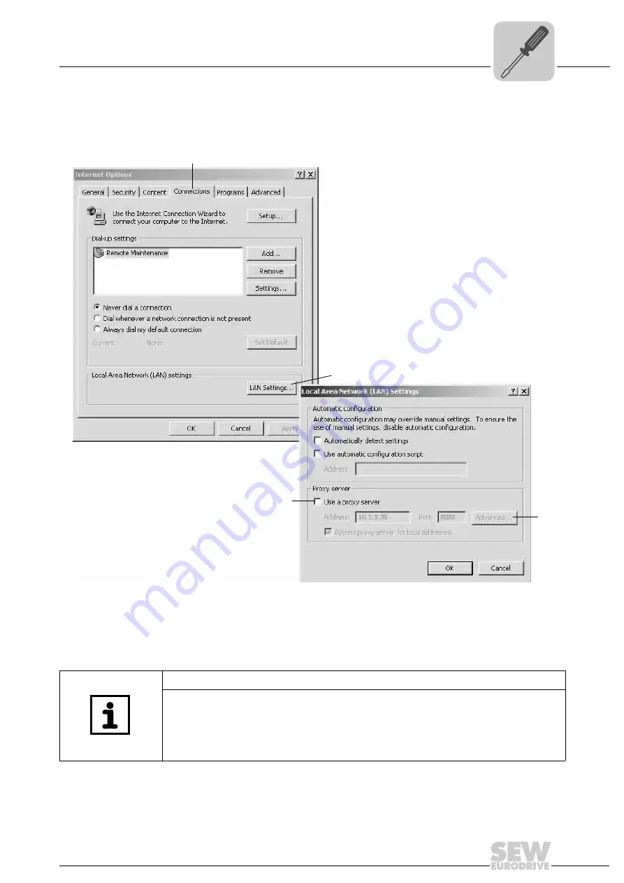
3. Select "Internet Options" from [Start] / [System Configuration]. The "Internet Proper-

ties" window is displayed (see following figure). Select the "Connections" tab [1] and
click on [LAN Settings] [2] in the "Local Area Network (LAN) Settings" field.

The "Local Area Network (LAN) Settings" window opens. If necessary, deactivate the
"Use a proxy server" [3] checkbox in the "Proxy server" group. This only needs to be
done to access the ORA11B configuration page. After successful configuration, you
can re-activate the "Use a proxy server" checkbox so that you can access other web-
sites or the configuration interface via the dial-up connection. 

63987AEN

[1]

[2]

[3]

[4]

NOTE

• The proxy server still needs to be deactivated and reactivated when a second net-

work card has been installed in the engineering PC.

• To bypass the proxy server for local addresses, click on [Advanced...] [4] to add the

IP address of ORA11B to the list of exceptions as an alternative to
deactivating/activating the proxy server.

Summary of Contents for MOVI-PLC advanced

Page 1: ...Drive Technology Drive Automation System Integration Services MOVI PLC advanced Controller Remote Maintenance via ORA11B Manual Edition 09 2008 16717228 EN ...

Page 2: ...SEW EURODRIVE Driving the world ...

Page 3: ...11B from a DIN rail 11 4 3 Connections and terminals at the front of ORA11B 13 4 3 1 Reset button 13 4 3 2 Connecting ORA11B to an analog telephone line 14 4 3 3 Connecting MOVI PLC advanced to ORA11B 16 4 3 4 Operating displays of the ORA11B option 16 4 4 Connections and terminals at the bottom of ORA11B 17 4 4 1 Voltage supply of ORA11B 17 5 Configuration 18 5 1 Used components topology 18 5 2 O...

Page 4: ...stood it Consult SEW EURODRIVE if you have any questions or if you require further information 1 2 Structure of the safety notes The safety notes in this manual are designed as follows Symbol SIGNAL WORD Nature and source of hazard Possible consequence s if disregarded Measure s to avoid the hazard Symbol Signal word Meaning Consequences if disregarded Example General hazard Specific hazard e g el...

Page 5: ... EURODRIVE to ensure safe operation and to achieve the specified product character istics and performance requirements SEW EURODRIVE assumes no liability for injury to persons or damage to equipment or property resulting from non observance of these operating instructions In such cases any liability for defects is excluded SEW EURODRIVE guarantees that the software is free from deficiencies in tit...

Page 6: ...rsons or damage to property Refer to the documentation for additional information 2 3 Target group Only qualified personnel is authorized to install startup or service the units or correct unit faults observing IEC 60364 or CENELEC HD 384 or DIN VDE 0100 and IEC 60664 or DIN VDE 0110 as well as national accident prevention guidelines Qualified electricians in the context of these basic safety note...

Page 7: ...ctrostatic energy and improper handling Prevent mechanical damage or destruction of electric components may pose health risk The following applications are prohibited unless the unit is explicitly designed for such use Use in potentially explosive areas Use in areas exposed to harmful oils acids gases vapors dust radiation etc 2 7 Other applicable documentation The following publications and docum...

Page 8: ... everywhere and ac cess via Ethernet is often not possible due to network administration requirements In this case using an analog modem connection is the best alternative ORA11B offers an analog modem a router and a 4 port switch It can be used to estab lish a connection via an analog phone line to a remote facility This enables the usual access to the MOVI PLC advanced controller and all units c...

Page 9: ...bles TAE N to RJ12 and RJ12 to RJ12 each 3 m long Optional scope of delivery Telephone adapter set for Europe suitable for Belgium France Italy Austria Switzerland part no 1811 216 1 Content of this manual This user manual describes the hardware required for remote maintenance of the MOVI PLC advanced controller and how a connection is established via the ORA11B modem NOTE For further function des...

Page 10: ...n the ORA11B with both latch hooks on the outer edge on the DIN rail accord ing to the following figure Rotate the ORA11B down towards the DIN rail until the movable latch hook clicks audibly ORA11B is now installed HAZARD Moisture and liquids can enter the interior of the ORA11B Severe or fatal injuries from electric shock ORA11B may not be used in wet or moist environments e g close to watercour...

Page 11: ...tions for removing ORA11B from a DIN rail Proceed as follows Remove all plug connectors Insert a screwdriver with blade width 4 5 mm in the movable latch hook see following figure HAZARD Open electric components Severe or fatal injuries from electric shock Switch off the power supply of the ORA11B and secure it against being switched back on inadvertently before removing the unit 64174AXX ...

Page 12: ...oving ORA11B from a DIN rail Assembly and Installation Notes Move and hold the screwdriver towards the ORA11B see following figure This draws apart the plastic spring of the movable latch hook First pull ORA11B forward and then upward and away from the DIN rail see follow ing figure 64185AXX 64181AXX 1 2 ...

Page 13: ...63AXX 1 Reset button 2 Telephone connection RJ45 plug connector 3 4 port Ethernet switch LAN 1 LAN 4 for network connection 4 Power LED 5 COM LED 6 Data LED 7 Status LED ORA11B RJ45 Line LAN 2 1 Power Reset COM Data Status LAN 4 LAN 1 LAN 3 3 4 2 1 2 3 4 5 6 7 Operation Meaning Press once briefly Resets ORA11B via software and restarts it Hold for at least 3 seconds Resets the hardware of ORA11B a...

Page 14: ...12 plug connector 2 in the RJ45 socket of the ORA11B and the TAE N plug connector 1 in the telephone jack see following figure 64202AXX ORA11B RJ45 Line LAN 2 1 Power Reset COM Data Status LAN 4 LAN 1 LAN 3 3 4 2 2 1 NOTE If the connection cables included in the scope of delivery do not fit your telephone jack you can use the telephone adapter of the optional telephone adapter set Europe part no 1...

Page 15: ... The following table shows the pin assignment of the RJ12 and TAE N plug connectors 64178AXX RJ45 TAE N Pin Description 1 E Not connected 2 a2 For connecting a downline telephone 3 a1 Incoming telephone line outside line or extension line 4 b1 5 b2 For connecting a downline telephone 6 W Not connected 1 2 3 4 5 6 6 E b2 b1 a2 a1 W 5 4 3 2 1 RJ12 TAE N ...

Page 16: ...atus of ORA11B and the re mote maintenance connection 64204AXX X35 X36 X37 2 4 6 1 3 5 X34 DHE41B 1 2 3 1 3 4 2 1 2 3 1 2 3 1 2 3 X32 X33 2 4 6 1 3 5 8 10 12 7 9 11 X31 T1 S1 L1 L2 L3 L5 X M L6 L7 L8 L9 L4 L10 ORA11B LAN 2 1 Power Reset COM Data Status LAN 4 LAN 1 LAN 3 3 4 2 RJ45 Line Designation Display Meaning 4 switch port status LEDs one LED each at LAN1 2 3 4 Yellow Green LED flashes Link wi...

Page 17: ...ions and terminals at the bottom of ORA11B Assembly and Installation Notes 4 4 Connections and terminals at the bottom of ORA11B 4 4 1 Voltage supply of ORA11B 64177AXX Terminal Designation Description 25 10 60 VDC Voltage supply 26 GND Mass 25 26 25 26 10 60 VDC GND Power Supply ...

Page 18: ...blished ORA11B Router switch IP address 192 168 10 3 Net mask 255 255 255 0 Modem Local address of the PPP connection 192 168 1 253 IP address of the remote end 192 168 1 254 MOVI PLC advanced IP address 192 168 10 4 Net mask 255 255 255 0 64005AEN ORA11B MOVI PLC advanced Ethernet cable for configuration purposes Engineering PC analog telephone line Ethernet cable LAN Data transmission NOTE Other...

Page 19: ...te dial in Yes Idle time 0 s Rings before call is answered 2 Activate NAT Activated Authentication for dial in Activated User name SEW Password ORA11B Authentication via PAP IP addresses for PPP connection WAN Own IP address 192 168 10 253 IP address of the remote end 192 168 10 254 NOTES If you reset ORA11B by performing a unit reset see chapter 4 3 1 all deviating settings e g IP address will be...

Page 20: ...address 192 168 10 3 is found on the housing of ORA11B The IP ad dress of the PC must be different from the IP address of ORA11B However the IP address of the PC must be from the same network e g 192 168 10 2 Set 255 255 255 0 as subnet mask Select the following menu items to make the settings Start Settings Network Connections Highlight the existing network connection and right click on the menu ...

Page 21: ...ver 3 checkbox in the Proxy server group This only needs to be done to access the ORA11B configuration page After successful configuration you can re activate the Use a proxy server checkbox so that you can access other web sites or the configuration interface via the dial up connection 63987AEN 1 2 3 4 NOTE The proxy server still needs to be deactivated and reactivated when a second net work card...

Page 22: ...nging default settings Once ORA11B has been connected to the PC via a patch or crossover cable you can enter the default IP address 192 168 10 3 in the browser You have to enter your user name and password to avoid unauthorized access see fol lowing figure The default settings are User name SEW Password ORA11B 12022AEN ...

Page 23: ...pens see following figure You can enter the default settings see chapter 5 3 1 under the respective menu item For more information refer to the online help under Display help text 12023AEN NOTE Do not use the browser button Update to update the content of the page To update the content of a page confirm your entries by clicking on OK in the configuration interface ...

Page 24: ...rk connection wizard see following figure To do so select Start Settings Network and Dial up Connections Make New Connection The network wizard is called 2 Select the network connection type Select the Dial up to private network radio but ton see following figure Click Next to continue 3 Select the unit you want to use for establishing the connection Tick the Modem checkbox see following figure Cl...

Page 25: ...ystem an outside line must first be selected by entering a 0 The comma after the 0 represents a pause that will last long enough to obtain the outside line The full number is then dialed Click Next to continue 5 In the Smart cards window select the Do not use my smart card radio button see following figure Click Next to continue 6 In the Connection availability window select the For all users radi...

Page 26: ...for the modem connection e g remote maintenance and tick the Add a shortcut to my desktop checkbox siehe following figure Click on the Finish button The Connect Remote Maintenance window opens 8 Before you can select anything you have to enter more settings see following figure Enter your user name and password here Click the Properties button The Remote Maintenance window opens 12037AEN 12038AEN ...

Page 27: ...onfiguration 9 Select the General tab In the Connect using selection field tick the Modem checkbox Click the Configure button 1 The Modem Configuration window is displayed see following figure If necessary deactivate the Enable modem compression 2 checkbox in the Hard ware features group Confirm your entries with OK 63997AEN 1 2 ...

Page 28: ... Internet protocol TCP IP checkbox 1 and click the Properties but ton 4 The Properties TCP connection window will open You do not have to set anything here Click the Advanced button The Advanced TCP IP settings window appears see following figure If you want to continue using an existing company intranet while the modem connec tion is active you have to deactivate the Use default gateway on remote...

Page 29: ...the menu items Start Settings System configuration System Hardware Device manager Modems Select the used modem Make a right mouse click to open the context menu and choose Properties see following figure Since dial up is to be via an outside line deactivate the checkbox Wait for dial tone before dialing 1 in the Dial control field Confirm your entry with OK 63999AEN 1 ...

Page 30: ...ting the modem connection Click the Dial button to close test the modem connection The connection is established see following figure To display the status of the modem connection highlight the shortcut on the desktop right click on it and select Status from the context menu see following figure 12038AEN 12039AEN 12040AEN ...

Page 31: ...5 Testing the modem connection Configuration The status of the modem connection is displayed see following figure Now ORA11B responds to a ping command see following figure MOVI PLC advanced also responds to a ping command see following figure 12041AEN 12042AEN 12043AEN ...

Page 32: ...d must contain the following entries under Ethernet 2 Ethernet2 IPAddress 192 168 10 4 IPAddress Netmask 255 255 255 0 Netmask Ethernet2 5 6 Establishing a connection on the engineering PC Select the entry Ethernet 1 in MOVITOOLS MotionStudio under Network communi cation connections Tick the Activate checkbox 2 then press the Edit button 3 see following figure 64000AEN 1 2 3 ...

Page 33: ... PLC Editor can be started as usual 64003AEN 1 2 NOTES To establish a stable connection you probably have to increase the timeout settings in MOVITOOLS MotionStudio and in the PLC Editor The timeout settings are avail able in the menu items MOVITOOLS MotionStudio Settings Options Communication timeout Proposal 15000 ms Network Configure communication connections Ethernet SMLP set tings Proposal 10...

Page 34: ... max current load DC 1 A AC 0 5 A Weight 300 g Dimensions width x height x depth 70 mm x 110 mm x 75 mm Temperature range 0 C 55 C Maximum permitted humidity 95 non condensing Protection class Housing IP40 Screw terminals IP20 Technical data of ORA11B modem Communication interface for incoming and out going PPP connections Analog 56k modem Transmission rate 56 kB s Supported data compression stand...

Page 35: ...Exclusion of liability 5 G General notes 4 Exclusion of liability 5 Right to claim under warranty 5 Structure of the safety notes 4 Use of the manual 4 I Introduction Content of this manual 9 M Mounting and installation notes Connections and terminals at the front of ORA11B 13 Mounting ORA11B to a DIN rail 10 Removing ORA11B from a DIN rail 11 Mounting ORA11B to a DIN rail 10 O Operating displays ...

Page 36: ...t reduces the cost and complexity of daily operations With a global presence that offers responsive and reliable solutions Anywhere With innovative technology that solves tomorrow s problems today With online information and software updates via the Internet available around the clock Drive Technology Drive Automation System Integration Services SEW EURODRIVE Driving the world www sew eurodrive co...

Reviews: