4
Installation
Gear units with solid shafts
20
Operating Instructions – Explosion-Proof VARIMOT
®
Variable Speed Gear Units and Accessories
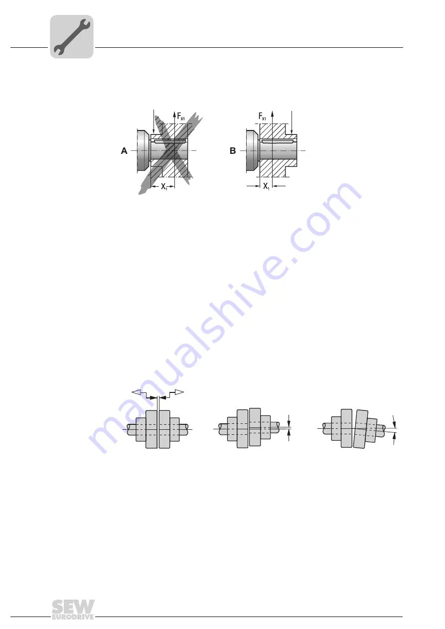
The following illustration shows the correct mounting arrangement (
B
)
of a gear wheel
or chain sprocket for avoiding impermissibly high overhung loads.
• Do not install input and output elements without a mounting device. Use the center
bore with the thread on the shaft end for positioning.
• Power transmission elements should be balanced after fitting and must not give rise
to any excessive radial or axial forces (see the "Geared Motors" catalog for permitted
values).
Mounting
couplings
Couplings must be mounted and balanced according to the information provided
by the coupling manufacturer:
a) Maximum and minimum clearance
b) Axial offset
c) Angular offset
52021AXX
Fig. 6: Correct mounting arrangement of a gear or sprocket wheel
A
Incorrect
[1]
Hub
B
Correct
[1]
[1]
03356AXX
Fig. 7: Clearance and misalignment for coupling mounting
a)
b)
c)


