


•
Accurate current limit protection is provided for both load and battery.
Automatic recovery from short circuit is provided with no current
tailing in short circuit operation.
•
Over voltage protection provides shutdown of power supply.
•
Inrush Surge limiting at turn on.
Battery LVD Operation
A low voltage disconnect (LVD) is provided to prevent deep discharge of
the battery.
When the mains has failed and the battery is supporting the load the
battery must be disconnected if its voltage falls below 10.2V
±
0.2V (20.5V
±
0.6V for BCE5) for longer than approximately 800mS.
The battery will reconnect in such a case when either;
1. The mains has recovered and the battery voltage is > 9.5V or;
2. The battery voltage has recovered to greater than 11.9V
±
0.3V
(23.5V
±
0.7V for BCE5) for longer than approximately 2 seconds.
The BATTERY output has protection incorporated against a reversed
battery connection. A reversed battery is left disconnected so that the
LOAD output can still run the load from mains power.
The quiescent current drain on the battery when the main has failed is
less than 30mA.
Indicators
A green LED (located next to the output connector) is illuminated during
normal operation. An alarm condition extinguishes the LED.
Alarm
A green LED and a pair of normally closed, floating relay are provided to
indicate alarm conditions. The LED is illuminated and the alarm relay
contacts are open during normal operation. An alarm condition
extinguishes the LED and closes the relay contacts. Alarm conditions are
defined as any one or more of the following events:
The mains fails, or drops to below nominal input.
The battery has been connected backwards.
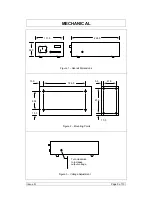
Output Voltage Adjustment
The output voltage is adjustable through the side of the power supply.
Use a flat blade pot adjuster to adjust the output voltage. Clockwise
rotation increases the output voltage.
Issue D
Page 6 of 13


