SET SET-2110 Technical Description Download Page 7

7 of 9


www.smart-e-tech.com


SET-2110 

Technical Description


Issue

 02   

24/05/2022 


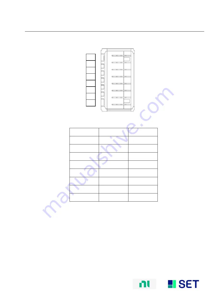
XJ3 Connector Pinout (Rear) 


Pins


Signal


Slot1/Slot2


V1+ 

Instrument 0+ 

V1- 

Instrument 0- 

V2+ 

Instrument 1+ 

V2- 

Instrument 1- 

V3+ 

Fault A 

V3- 

Fault B 

V4+ 

Fault C 

V4- 

Fault D 

XJ3 Connector Pin Assignments 


Summary of Contents for SET-2110

Page 1: ...ote Before you begin complete the software and hardware installation procedures applicable to your application Note The guidelines in this document are speci c to the SET 2110 The other components in...

Page 2: ...environment This product is intended for use in industrial locations However harmful interference may occur in some installations when the product is connected to a peripheral device or test object o...

Page 3: ...of both fault bus signal pairs can be selected dynamically for every channel The SET 2110 Fault Insertion Card also provides the ability to generate short circuits between a channels positive and neg...

Page 4: ...36 6 21 35 5 20 34 4 19 33 3 18 32 2 17 31 1 16 P3 2 P3 2 P3 1 P3 1 P3 0 P3 0 EN3 EN2 P2 2 P2 2 P2 1 P2 1 P2 0 P2 0 NC NC P1 2 P1 2 P1 1 P1 1 P1 0 P1 0 EN1 EN0 P0 2 P0 2 P0 1 P0 1 P0 0 P0 0 P3 3 P3 3...

Page 5: ...5 of 9 www smart e tech com SET 2110 Technical Description Issue 02 24 05 2022 XJ2 Connector Pinout Rear...

Page 6: ...3 P6 3 P2 3 P6 3 NC P2 2 P6 2 P2 2 P6 2 9 GND GND GND GND GND 10 P3 1 P7 1 P3 1 P7 1 NC P3 0 P7 0 P3 0 P7 0 11 P3 3 P7 3 P3 3 P7 3 NC P3 2 P7 2 P3 2 P7 2 12 NC NC NC NC NC 13 NC NC NC NC NC 14 NC NC...

Page 7: ...scription Issue 02 24 05 2022 XJ3 Connector Pinout Rear Pins Signal Slot1 Slot2 H V1 Instrument 0 G V1 Instrument 0 F V2 Instrument 1 E V2 Instrument 1 D V3 Fault A C V3 Fault B B V4 Fault C A V4 Faul...

Page 8: ...gnized by chassis and ready to communicate Amber Chassis is communicating Error Handling LED Name LED Behavior Actions PWR Off Check power supply of chassis Check external power supply if used PWR Bli...

Page 9: ...ics Property Condition Value Comment Module Dimensions Excluding ejector 144 32 mm x 30 48 mm x 302 mm H x W x D Standard SLSC card size Front Panel Connector 2x female DB 44 high density D Sub with 4...

Reviews: