


SerVision
Embedded Video Gateway System Guide
Configuring Sensor and Activator Settings
127
To configure a sensor as a CCTV display switch:
1. In the
Main Menu
, under
Sensors
, click the appropriate sensor (see above). The
Sensor
configuration screen
opens.
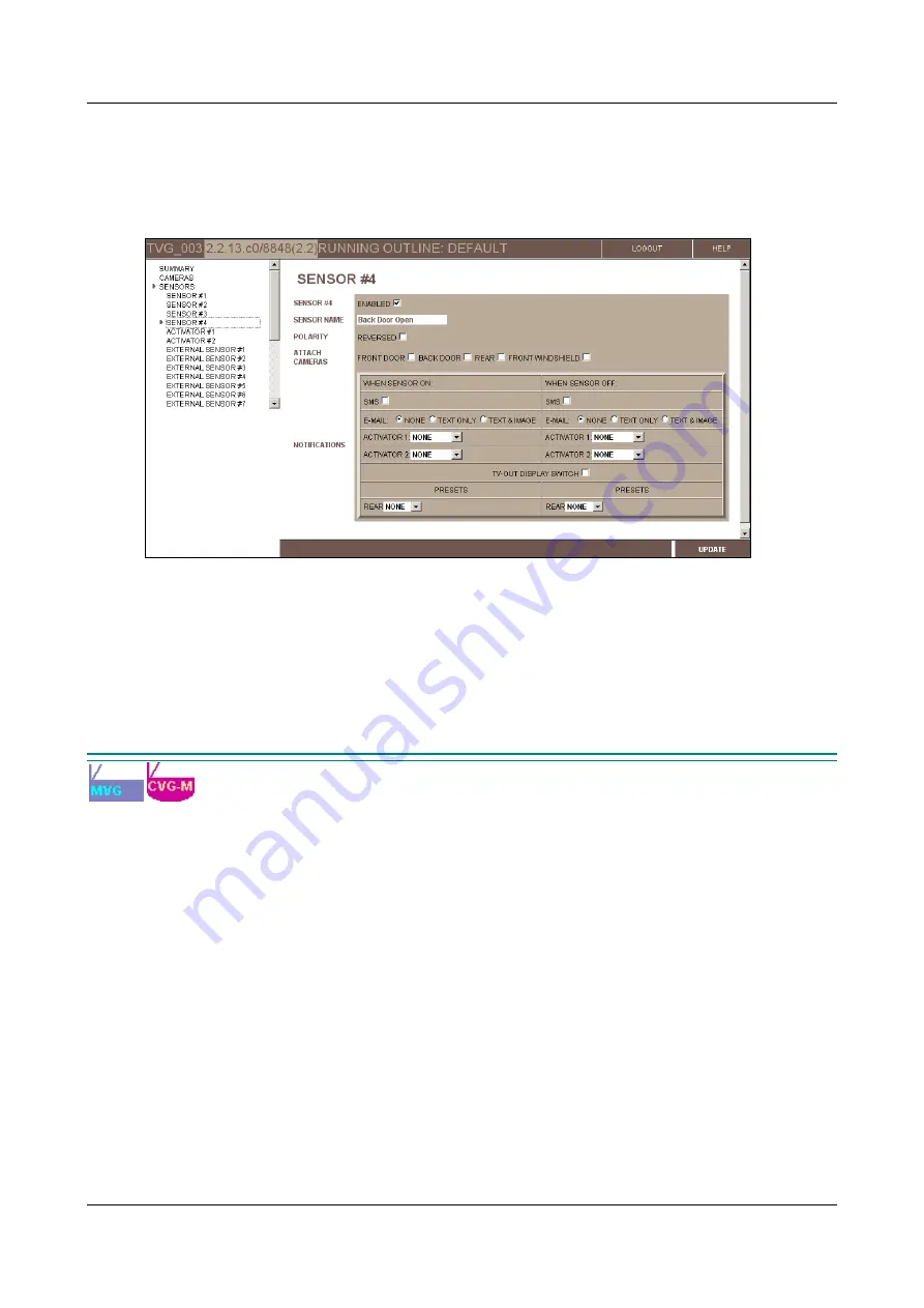
2. Select the
Enabled
checkbox. The fields required to configure the sensor settings are added to the screen.
Figure 137: Sensor #4 configuration screen (MVG, UVG)
Note:
Every time the CCTV display is switched, a sensor event is triggered. If notification settings are
activated, notifications will be triggered each time the display is changed. For additional information about
configuring the notification settings, see
Configuring Sensors and Activators
3. Select the
TV-Out Display Switch
checkbox.
4. Click
Update
, and then save the settings. They will be implemented after the unit is restarted (see
Configuring an Activator as a Power Switch
When a Video Gateway is installed in a vehicle, the cameras and other peripheral devices connected to it usually
receive their power directly from the vehicle battery. Normally, the Video Gateway is configured to shut down
whenever the vehicle ignition is turned off. Because the peripheral devices do not draw their power from the Video
Gateway, they will keep drawing power from the vehicle battery even when the Video Gateway is off. To cause
these devices to shut down when the vehicle ignition is turned off, their power supplies can be routed through an
activator connector on the unit. When this is done, the activator must be configured to cut off the power supply that
is routed through it when the ignition turns off.
To configure an activator as a power switch:
1. In the
Main Menu
, under
Sensors
, click the appropriate activator (e.g.,
Activator #1
if
Out1
is being used as
the power switch). The
Activator
configuration screen opens.
2. Select the
Enabled
checkbox. The fields required to configure the activator settings are added to the screen.
3. Under
Activator Type
, select
Bypass
. (All of the other fields in the screen are hidden, because they are not
relevant when the activator connector is used in this way.)