


Each step contains a variety of numbers, lines, and symbols. The numbers represent the order in
which the parts should be assembled. The lines are described below.
Each step contains a variety of symbols described below.
Assembly path of one item into another
Detail view to explain assembly or order of parts better.
Group of items (within lines) should be
assembled first
Default set-up: This symbol indicates the default setup.
Glue one item to another
Silicone grease: apply a small amount of grease to the parts shown.
Direction the item should be moved
Grease: apply a small amount of grease to the parts shown.
Left and right parts should be assembled in the same way.
Connect one item to another
Thread lock: apply a small amount on the parts shown. Before to apply the threadlock,
make sure to degrease the parts very well, as otherwise the threadlock will not work.
Gap between two items
Silicone oil: use the indicated silicone oil for the shocks and differentials.
Parts or items not included in the kit.
Optional part, not standard in the kit.
Carefull, read and check very well.
Step number; the order in which you should
assemble the indicated parts
1
3
2
Apply a small amount of cyano glue. Use wear protection for eyes and hands.
Length after assembly
Press/Insert one item into another
3
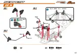
HOW TO USE THE MANUAL
ICONS DESCRIPTION
LINES DESCRIPTION
Summary of Contents for Viper 989e
Page 1: ...INSTRUCTION MANUAL ...
Page 4: ...M4x8 1 2 M4x8 M3x8 M3x6 M3x6 M3x8 M3x6 STEP 2 STEP 1 4 BAG 1 REAR ASSEMBLY ...
Page 5: ...32 5mm M4x10 M4x10 1mm M4x8 3 4 M4x8 1 2 STEP 3 STEP 4 5 ...
Page 6: ...M4x8 M3x8 M3x8 M4x8 R12 2 5x22 R12 R12 1 2 2 2 5x22 BAG 2 STEP 5 STEP 6 6 ...
Page 10: ...3 3 mm 3 mm REAR TRACK WIDTH STEP 11 10 ...
Page 11: ...12 1 11 5 mm 12 2 1 2 2 3 4 4 1 M3x8 M3x18 M3x18 M3x8 M3x18 STEP 12 11 ...
Page 12: ...13 1 M4x8 M4x8 M4x8 STEP 13 12 BAG 4 ...
Page 21: ...45 5 mm 6 8 mm 7 mm FRONT CAMBER AND TRACK WIDTH 21 STEP 26 STEP 27 ...
Page 23: ...M4x8 M4x4 M4x8 M4x4 M4x4 M4x8 23 STEP 30 ...
Page 30: ...M3x4 M3x4 M3x6 M3x4 M3x6 STEP 43 30 ...
Page 31: ...M3x10 M3x10 STEP 44 31 ...
Page 32: ...M3x6 M3x8 M3x8 M3x8 M3x6 32 STEP 45 ...
Page 40: ...905122 904136 401653 110122 110104 110129 110118 110104 40 FINAL EXPLODED VIEW ...
Page 43: ...INSTRUCTION MANUAL Manual Viper 989E 57591 1 ...