background image

6.2. A

I

M+: DETECT

I

NG AND M

I

T

I

GAT

I

NG

I

NTERFERENCE

6.2.2 Wideband interference mitigation

Wideband interference of GNSS signals can be caused unintentionally by military and civilian
ranging and communication devices. There are also intentional sources of interference from
devices such as chirp jammers. The wideband interference mitigation system (WB

I

) of the

PolaRx5S can reduce the e

ect of both types of interference on GNSS signals.

Configuring WBI mitigation

The Wideband

I

nterference Mitigation system (WB

I

) can be enabled by selecting

on

as shown

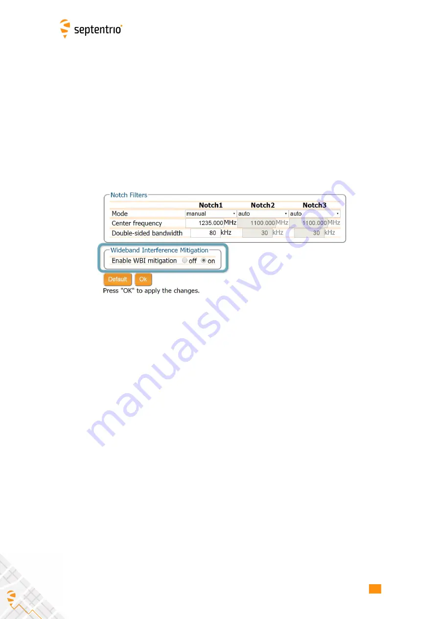
in Figure 6-5. Enabling WB

I

will increase the power consumed by the PolaRx5S by about

160 mW.

Figure 6-5:

Select

on

to enable Wideband

I

nterference Mitigation then

OK

to

apply the new setting

65

Summary of Contents for PolaRx5S

Page 1: ...PolaRx5S User Manual ...

Page 2: ...rt functions specific to certain variants While we try to keep the manual as complete and up to date as possible it may be that future features functionality or other product specifications change without prior notice or obligation The information contained in this manual is subject to change without notice We recommend you to look for new or updated information in our Knowledge Base at https custom...

Page 3: ...ING AN ANTENNA 13 3 3 CONNECTING TO THE POLARX5S VIA THE WEB INTERFACE 14 3 3 1 Using the USB cable 14 3 3 2 Over WiFi 16 3 3 3 Using the Ethernet cable 18 4 Reference station operation 19 4 1 HOW TO CONFIGURE THE POLARX5S AS AN RTK BASE STATION 19 4 2 CONFIGURING THE POLARX5S NTRIP CASTER 24 4 3 HOW TO OUTPUT A PPS PULSE PER SECOND SIGNAL 27 4 4 HOW TO ENABLE THE NTP SERVER 28 4 5 HOW TO LOG DATA...

Page 4: ...ING 61 6 2 AIM DETECTING AND MITIGATING INTERFERENCE 63 6 2 1 Narrowband interference mitigation 64 6 2 2 Wideband interference mitigation 65 6 3 HOW TO LOG DATA FOR PROBLEM DIAGNOSIS 67 6 3 1 Support SBF file 67 6 3 2 Diagnostic Report 69 6 4 ACTIVITY LOGGING 70 6 5 HOW TO USE THE MONITORING FEATURE TO CONFIGURE THE RECEIVER TO POWER DOWN ON LOW VOLTAGE 71 6 5 1 Configuring the monitoring feature 7...

Page 5: ...onnectors 94 Appendix C Cables 95 Appendix D LED behaviour 96 Appendix E 100 Hz Output Rate 98 Appendix F Real Time ISMR data 99 Appendix G TEC Calibration 100 Appendix H RxTools 105 Appendix I Connecting to the PolaRx5S using RxControl 106 5 ...

Page 6: ...06 95 EC Low Voltage Directive both amended by the CE marking directive 93 68 EC With regards to EMC these devices are declared as class B suitable for residential or business environment 1 1 2 ROHS WEEE Notice PolaRx5S receivers are compliant with the latest WEEE RoHS and REACH directives For more information see www septentrio com en environmental compliance 6 ...

Page 7: ...uble isolated construction and must match the specifications of the provided power supply Statement 2 Ultimate disposal of this product should be handled according to all national laws and regulations Statement 3 The equipment and all the accessories included with this product may only be used according to the specifications in the delivered release note manual or other documents delivered with the ...

Page 8: ...te has a dedicated Support section http www septentrio com support where the User Manual the Firmware Reference Guide and the latest officially supported Firmware version are readily available for download Further information can be found on our website or by contacting Septentrio s Technical Support department In case the PolaRx5S does not behave as expected and you need to contact Septentrio s Tec...

Page 9: ...he WiFi button to turn the WiFi module off or on The REF OUT frequency reference output in power critical applications REF OUT can be turned off with the setREFOUTMode command The following table shows the nominal power consumption measured when 12 VDC is supplied to the PWR connector Configuration Power Consumption GPS GLONASS L1 tracking and PVT 3 5W GPS GLONASS L1 L2 tracking and PVT 3 6W GPS L1 L...

Page 10: ...65 RohS CE FCC Class B Part 15 2 2 PolaRx5S design 2 2 1 Front panel The front panel layout of the PolaRx5S is shown in Figure 2 1 A description of the front panel sockets as well as their PIN assignments can be found in Appendix A The cables available for use with the PolaRx5S are listed in Appendix C and the LED behaviour is described in Appendix D Figure 2 1 PolaRx5S front panel layout 10 ...

Page 11: ...n of a back up battery to the ODU PWR connector The battery will only be used in case of an outage of the power over Ethernet The current power source PWR or Ethernet connector and the voltage at the PWR connector are reported in the PowerStatus SBF bock 2 2 4 Power Button When power is initially applied to the PWR or Ethernet connector or after a power outage the receiver always starts up without...

Page 12: ...the receiver is operating pressing the WiFi button turns WiFi on and off in turn The red WiFi LED next to the WiFi button lights when WiFi is enabled 2 2 6 Internal memory The PolaRx5 has a 16 GB Memory for internal data logging Data can be logged in SBF RINEX BINEX NMEA or RTCM MSM format and may be retrieved via the âĂŸLoggingâĂŹ menu of the web interface 2 2 7 External memory The PolaRx5S can lo...

Page 13: ...Front panel power socket The PolaRx5S can also be powered over Ethernet PoE as described in Section 2 2 3 or by supplying 9 to 30 V via PIN 1 of the open ended power cable CBLe_PWR_OE as detailed in Appendix A 8 3 2 Connecting an antenna The rear panel of the PolaRx5S has a TNC connector labelled MAIN to connect a GNSS antenna Connect an antenna to the PolaRx5S using an antenna cable as shown in F...

Page 14: ...thods 3 3 1 Using the USB cable Connect the USB cable CBLe_USB to the socket labelled COM3 4 USB on the front panel of the PolaRx5S as indicated in Figure 3 3 Figure 3 3 Connecting to the front panel USB socket The first time that the USB cable is connected to your pc you may be prompted to allow installation of drivers which can take several minutes When the drivers have been installed it is recom...

Page 15: ...ctivate the drivers The USB connection on the PolaRx5S functions as network adapter and the DHCP server running on the receiver will always assign the PolaRx5S the IP address 192 168 3 1 To connect to the PolaRx5S you can then simply open a web browser using the IP address 192 168 3 1 as shown in Figure 3 5 Figure 3 5 Connect to the Web Interface of the PolaRx5S over USB using the IP address 192 1...

Page 16: ...nt panel WiFi button to turn on the WiFi modem When active the red WiFi led will be lit On your PC or tablet search for visible WiFi signals the PolaRx5S identifies itself as a wireless access point named PolaRx5S serial number The serial number of the PolaRx5S can be found on an identification sticker on the receiver housing Select and connect to the PolaRx5S as shown in Figure 3 7 Figure 3 7 Selec...

Page 17: ...n your PC has connected to the PolaRx5S WiFi signal you can open a web browser using the IP address 192 168 20 1 as shown in Figure 3 8 Figure 3 8 Connect to the Web Interface of the PolaRx5S over WiFi using the IP address 192 168 20 1 on any web browser 17 ...

Page 18: ...g a DHCP server The IP address assigned to the receiver will be associated with the hostname PolaRx5S xxxxxxx where xxxxxxx are the 7 digits of the serial number of the GNSS Receiver Board GRB inside the PolaRx5S This number can also be found on an identification sticker on the receiver housing You can then make a connection to the receiver using the web address http PolaRx5S xxxxxxx Figure 3 10 sh...

Page 19: ... be selected in the Position window of the Station menu as shown in Figure 4 1 Figure 4 1 Setting the PolaRx5S base station position to static Set the correct position An accurate position of the antenna that is connected to the PolaRx5S should also be set The default setting of auto can be used for demonstrations however for most other purposes a properly surveyed position is advisable In the exa...

Page 20: ...CM3 output to start the sequence of configuration steps RTCMv3 is the most compact and robust differential correction format and it is recommended to use this format where possible Select the Ethernet port you wish to use avoiding the commands port 28784 the webserver port 80 the FTP port 21 as well as the default NTRIP port 2101 and the NTP port 123 The example shown in Figure 4 3 uses port 28785 T...

Page 21: ... them you can now connect to the configured Ethernet port of the PolaRx5S using a terminal emulator tool such as Data Link The Ethernet IP address you need can be found in the information bar at the top of the web interface In the example shown in Figure 4 4 the IP address is 192 168 105 246 Figure 4 4 The IP address of the PolaRx5S can be found on the information bar Data Link is part of Septentri...

Page 22: ...the Data Link terminal emulator tool to connect to the PolaRx5S Ethernet port over which differential corrections have been configured When connected to the output correction stream click on the Show Data button on Data Link and you should see output similar to that shown in Figure 4 6 Figure 4 6 The RTCMv3 differential correction stream output from the IPS1 Ethernet connection of the PolaRx5S 22 ...

Page 23: ...ed in this example using Data Link the Data Streams field on the Corrections Output window should now show the active blue connection shown in Figure 4 7 and the corrections output icon in the information panel should appear active Figure 4 7 Web Interface showing differential corrections output over an Ethernet connection 23 ...

Page 24: ...wish to send correction data the default port is 2101 Click on New mount point as indicated in Figure 4 9 Select Yes to enable the mount point and give it a name This is the name that will appear in the caster source table Up to 3 mount points can be defined each with a different name You can also select the type of Client authentication for the mount point none any client can connect without loggin...

Page 25: ...fine at least one user The user name and password are the credentials needed for the NTRIP client rover to access the correction stream In the Client Users section click on New User as shown in Figure 4 10 Enter a User Name and Password for the user and select the mount points that they will have access to Up to 10 NTRIP clients can log in as a particular user Click Ok to apply the settings Figure ...

Page 26: ... GGA message to the caster as was the case in Figure 4 12 then their position will also be visible Figure 4 11 Connecting as a client to the PolaRx5S NTRIP Caster On the NTRIP Client side Rover receivers can connect to the NTRIP Caster by entering its IP address and Port as shown in Figure 4 12 After clicking Ok the mount point source table will be filled and a mount point can be selected The user ...

Page 27: ... rear panel of the PolaRx5S Step 2 Configure the PPS settings You can configure the PPS settings on the Timing window of the GNSS menu as shown in Figure 4 14 Figure 4 14 PPS configuration field in the web interface The Interval is the time interval between successive timing pulses and is selectable between 10 ms and 10 s The default Polarity of the PPS signal is a low to high transition which can be ...

Page 28: ...e PPS generation time which is extrapolated from the last available PVT information may start to drift To avoid large biases the receiver stops outputting the PPS pulse when the last available PVT is older than the specified MaxSyncAge The MaxSyncAge is ignored when TimeScale is set to RxClock Step 3 Click on Ok to apply settings The new configuration can also be saved as the boot configuration by cl...

Page 29: ...here are two options either the receiver stops logging when the memory is full or it continues logging by making space for new files by deleting the oldest The default setting is Delete oldest Figure 4 16 Selecting what you wish to happen when the internal 16 GB memory is full Step 2 Configuring a logging session On the Log Sessions window of the Logging menu you can check which logging sessions hav...

Page 30: ...ternal Disk and Never for Auto Delete have been selected In the Edit SBF Stream window the messages required for RINEX generation have been selected as well as those useful for the Support department for diagnosing problems SBF messages can also be selected individually Figure 4 18 Follow the sequence of windows to fully configure the logging session Please note that this setting is overruled by th...

Page 31: ... the Log Sessions window will show a summary of the defined logging sessions as in Figure 4 19 An estimate of the daily size of data generated with the current logging configuration is also given Figure 4 19 A summary of the newly defined logging sessions showing the expected amount of data generated daily 31 ...

Page 32: ...rnal memory device connected the new device should be visible in the Log Sessions window as shown in Figure 4 21 If the device is not formatted or the formatting is not compatible with the receiver file system you will be prompted to format the device This can be done by clicking on the Format button Figure 4 21 With a 2 GB external USB memory device connected to the PolaRx5S New logging sessions c...

Page 33: ...d in the Edit Session window after configuring SBF or RINEX logging as shown in Figure 4 23 FTP push will create the folder data on the remote server if it does not yet exist If file transfer fails the receiver will retry after the Retry Interval which has been selected as 15 minutes in this example Figure 4 23 Configure pushing of RINEX files to an external FTP server You can check that the FTP serve...

Page 34: ... PolaRx5S both on its internal memory and to an external USB device can be downloaded using the web interface on the Disk Contents window of the Logging menu Each logging session is logged to a separate folder Individual files can be downloaded by clicking on the green download arrow next to the file name as shown in Figure 4 25 If you need to download multiple files from the receiver it may be more ...

Page 35: ...how to connect using FTP with FileZilla over both the USB connection 192 168 3 1 and over Ethernet PolaRx5S 3010305 The DSK1 folder contains data files logged on the internal memory while DSK2 contains files logged to an external device Figure 4 26 Downloading logged data files using the PolaRx5S FTP server with a FileZilla client DSK1 files logged on the internal memory DSK2 files logged on an externa...

Page 36: ... 6 HOW TO ACCESS LOGGED DATA Figure 4 27 Downloading logged data files using the FTP server with Windows File Explorer DSK1 files logged on the internal memory DSK2 files logged on an external USB device 36 ...

Page 37: ... them from being deleted To configure POEL create a new log session as described in Section 4 5 and select Type âĂŸPreserve on EventâĂŹ Currently âĂŸEventsâĂŹ refers to hardware events a voltage transition registered by either the Event A or the Event B pins Data can be preserved from x minutes before until y minutes after event as shown in Figure 4 28 The maximum amount of time data can be preserv...

Page 38: ...ull The files in unused or disabled log sessions are first to be deleted The receiver then scans the enabled low priority sessions The oldest file in these sessions is identified and deleted If no file could be deleted the receiver scans the medium priority sessions and finally it will scan the high priority sessions Preserved files are the last to be deleted but in case the disk fills with preserved files...

Page 39: ...g to Server Note that it is disabled by default Once the server is enabled all the other P2PP settings can be configured as shown in Figure 4 30 The Port option allows to select the COM port to be used for the point to point communication Next the client and server IP s will need to be set The ClientIP sets the IP address that will be given to the client remote from the receiver s perspective when ...

Page 40: ...assword needs to be set in order to successfully configure this feature Figure 4 31 Enabling P2PP authentication Finally Connect Timeout determines the maximum amount of time in seconds that a connection attempt may consume before being refused Meanwhile Activity Timeout sets the maximum time in seconds that a connection may be idle no data transfer before it is disconnected When a timeout occurs t...

Page 41: ...lternative to FTP for RINEX or SBF file submission from the PolaRx5S receivers and supports OpenAM for authentication To learn more about the CloudIt feature and learn how to set it up please check the knowledge base on the Septentrio website 41 ...

Page 42: ...RxLogger Septentrio provides the RxTools suite of GUI tools among which is RxLogger The RxLogger tool provides an easy and convenient way to log and monitor ISMR data from the PolaRx5S A short description of the various RxTools and how to install them can be found in Appendix H This section details how to use RxLogger for ISMR file generation 5 2 1 Connecting To the Receiver The first time you run R...

Page 43: ... receiver Raw data high rate phase and amplitude and low rate support data are stored in SBF Septentrio Binary Format Raw data files will be referred to as SBF files in the remainder of this chapter In the main window of RxLogger on the Global tab select the directory where data files will be logged In the example shown in Figure 5 2 data will be stored in the folder C Users dean DATA 43 ...

Page 44: ...rectory will be created under the directory specified in the Global tab with the name being formed from a concatenation of the two digit year number and the 3 digit day of year Within each of the daily directories the hourly SBF files follow the IGS file naming convention ssssdddf yy_ yy two digit year f file sequence character within day A 1st hour 00h 01h B 2nd hour 01h 02h X 24th hour 23h 24h ddd ...

Page 45: ...ion name designator as SEPT Figure 5 4 shows an example of data files logged on February 26 2016 The files with the 16_ extension are SBF files containing the raw data from the receiver The files with the 16_ ismr extension are the post processed files containing the scintillation indices Section 5 2 4 describes how to configure post processing actions Figure 5 4 An example of hourly SBF and ISMR files l...

Page 46: ... following SBF blocks should be logged At an interval of 20ms 50Hz IQCorr At an interval of 1s 1Hz MeasEpoch MeasExtra At an interval of 10s ReceiverStatus ChannelStatus ReceiverSetup At an interval of OnChange GPSNav GLONav GALNav BDSNav QZSNav Click the Add Stream button to add a new column in the window Figure 5 5 Select the SBF blocks and logging rates needed for ISMR file generation The MeasEp...

Page 47: ...g action From there you can select ISMR Conversion from the drop down list as shown in Figure 5 6 Then click on Next Figure 5 6 Selecting automatic generation of ISMR files from SBF data files On the ISMR Parameters page shown in Figure 5 7 you can select the desired phase detrending cut off frequency the default is 0 10 Hz You may want to reduce the number of columns in the ISMR file if for example y...

Page 48: ...sion of SBF to ISMR format After clicking Next you can select then select which compression to apply to the ISMR file As these files are typically small 200kbytes file compression is not normally required Figure 5 8 Selecting not to compress the generated ISMR data files 48 ...

Page 49: ...l select the default settings as shown in Figure 5 9 This will store the ISMR files in the same directory as the raw SBF files Figure 5 9 Storing the generated ISMR files in the default location alongside the logged raw SBF files On the final configuration window shown in Figure 5 10 you are prompted to enter a name for the post processing action and a description The name used is for information only a...

Page 50: ...tart Logging to start data logging 5 2 5 Monitoring logging and ISMR status In the Logger Info window of the Status tab of the main window of RxLogger as shown in Figure 5 11 you can follow the progress of the logging and post processing and get a snapshot of the ISMR indices Figure 5 11 The Logger Info field gives summary information on the ISMR indices as well as logging and post processing Data ...

Page 51: ...new post processing action as shown in Figure 5 12 This time in the Post Process Action Input and Type window just click Next as there is no conversion to apply You can now select the compression program you wish to use Figure 5 12 Add a second post processing action As before enter a name and description of this new post processing action and click Finish Make sure to check the Remove Source File...

Page 52: ...ser s home directory Thus the configuration steps described above need only be carried out once 5 2 8 Starting RxLogger from the command line RxLogger can be launched from the command line as shown in Figure 5 14 Figure 5 14 Launching RxLogger from the command line Rxlogger starts in the configuration as stored in the rxlogger conf file The A command line option causes RxLogger to immediately start l...

Page 53: ...0 8 1462 540360 10 00000074 232 30 48 0 0 045 0 022 0 019 0 024 0 030 0 031 0 031 3 654 0 047 14 184 0 022 13 899 0 027 13 575 0 021 14 460 0 017 4270 0 4262 37 6 1 4 1462 540360 23 00000074 231 68 48 0 0 039 0 000 0 018 0 023 0 029 0 031 0 031 5 799 0 074 6 616 0 005 7 006 0 003 6 473 0 005 8 339 0 010 11954 0 11948 37 7 1 2 1462 540360 17 00000074 152 15 48 0 0 037 0 000 0 017 0 022 0 028 0 030 ...

Page 54: ...E5 Use E5AltBOC as third Galileo signal type default is E5b Note that multiple s options can be provided e g sC2B2a sE3E6 V Display the version of sbf2ismr h Display this help screen Format of the ISMR output file Note The default signals available the ISMR file are as follows Other signals can be selected with the s option Sig1 L1CA for GPS GLONASS SBAS QZSS E1 for GALILEO B1I for BeiDou and L5 f...

Page 55: ...ol 54 AvgCCD on Sig3 average of code carrier divergence meters Col 55 SigmaCCD on Sig3 standard deviation of code carrier divergence meters Col 56 Sig3 lock time seconds Col 57 SI Index on Sig3 dimensionless Col 58 SI Index on Sig3 numerator only dB Col 59 p on Sig3 phase spectral slope in the 0 1 to 25Hz range dimensionless Col 60 T on Sig1 phase power spectral density at 1 Hz rad 2 Hz Col 61 T o...

Page 56: ...ple SVID values in the range 1 37 refer to GPS satellites You can find the full list of satellite constellation SVID ranges in the SBF Outline section of the PolaRx5S Reference Guide Supported Signals For each satellite the ISMR file contains iono indices S4 Phixx for up to three signals as listed in the table below The signals in italic can be selected with the s option of sfb2ismr Satellite system...

Page 57: ...10 30 and 60 seconds More specifically Phi01 is the average of the 60 standard deviations computed over 1 s intervals during the last minute Phi03 is the average of the 20 standard deviations computed over 3 s intervals during the last minute Phi10 is the average of the 6 standard deviations computed over 10 s intervals during the last minute Phi30 is the average of the 2 standard deviations comput...

Page 58: ...tion TGD1 TGD2 transmitted by BeiDou satellites is applied QZSS L1CA L2C The correction TGD transmitted by QZSS satellites is applied SBAS L1CA L5 Uncorrected IRNSS Only one frequency L5 of IRNSS satellites is available so not possible to determine TEC values For GPS the TEC is based on the P code measurements as opposed to the C A code on L1 and L2 There is therefore no need for correction of the...

Page 59: ...gth Columns 31 45 and 59 provide the opposite of the slope often denoted p of the phase PSD in log log axes where the PSD is obtained by computing the FFT of the 3000 detrended phase samples in the last minute The slope is computed by fitting a linear polynomial to the PSD over the 0 1 to 25 Hz frequency range The figure below illustrates the way the slope is computed In the example depicted p is ab...

Page 60: ...7 0 23 0 09 R08 42 39 2 L1CA 16188 49 1 0 17 0 07 0 11 L2CA 14929 46 8 0 17 0 07 0 08 S38 23 L1CA 65534 44 5 0 80 0 06 0 45 R23 13 76 5 L1CA 13454 44 2 0 27 0 15 0 08 L2CA 13475 40 3 0 31 0 23 0 08 R12 22 75 8 L1CA 2787 47 7 0 23 0 08 0 11 L2CA 2546 42 7 0 21 0 08 0 09 R07 13 73 5 L1CA 25367 42 7 0 43 0 17 0 10 L2CA 20359 42 4 0 27 0 10 0 08 S33 32 L1CA 20553 42 3 0 83 0 08 0 50 R10 38 80 4 L1CA 1...

Page 61: ...the receiver board and the voltage supplied is also shown The icons to the right of the information bar show that in this example the position of the receiver is fixed the overall signal quality is Excellent 5 out of 5 bars and the receiver is logging both internally Int Logging and to an external USB memory device Ext Logging The Corrections icon indicates that differential corrections are being se...

Page 62: ... line that there are no satellites from that particular constellation in tracking More information can be found in the Satellites and Signals page on the GNSS menu The Logging field summarises the current logging sessions and disk capacities The complete logging information and configuration windows can be found via the Logging menu The Data Streams field gives and overview of the data streams into g...

Page 63: ...deband interference both intentional and unintentional can be mitigated by turning on the WBI mitigation system The WBI system also reduces more effectively than traditionally used pulse blanking methods the effects of pulsed interferers The spectrum view plot In the Spectrum window of the GNSS menu you can monitor the RF spectrum and configure three separate notch filters to cancel out narrowband int...

Page 64: ...de as shown configured for Notch1 in Figure 6 3 the region of the affected spectrum is specified by a centre frequency and a bandwidth which is effectively blanked by the notch filter Figure 6 3 Configuring the first notch filter Notch1 at 1235 MHz With the Notch1 settings as shown in Figure 6 3 the L2 band after the notch filter After IM is shown in Figure 6 4 with the blanked section clearly visible Figu...

Page 65: ...m devices such as chirp jammers The wideband interference mitigation system WBI of the PolaRx5S can reduce the effect of both types of interference on GNSS signals Configuring WBI mitigation The Wideband Interference Mitigation system WBI can be enabled by selecting on as shown in Figure 6 5 Enabling WBI will increase the power consumed by the PolaRx5S by about 160 mW Figure 6 5 Select on to enable ...

Page 66: ...the effect of the interference is dramatically reduced to the extent that the small signal bump at the GPS L1 central frequency of 1575 MHz is clearly visible as Figure 6 7 shows In this particular test the interference signal caused the receiver to fall back to the less precise DGNSS or standalone positioning modes With WBI mitigation enabled however the receiver was able to maintain an RTK fix pos...

Page 67: ...ing a new logging session On the menu bar select Logging then the Log Sessions window where you can define a new logging session Figure 6 8 Click on the Create button to start defining a new logging session Step 2 Select to log the Support data blocks In the Edit Session window click on SBF Logging and New SBF stream as usual In the final Edit SBF Stream field make sure to select the Support option as...

Page 68: ...ing session selecting Support in the Edit SBF Stream field When logging has been correctly configured the Log Sessions window will show the newly defined session as active as indicated in Figure 6 10 Figure 6 10 The Log Sessions window showing an active logging session 68 ...

Page 69: ...igure 6 11 Click on the download icon next the SBF file you want to download Figure 6 11 Click on the green download icon to next to the file you want to download 6 3 2 Diagnostic Report A Diagnostic Report can be generated under the Admin About tab on the Web interface as shown in Figure 6 12 and saved to your PC Figure 6 12 Generate a Diagnostic Report 69 ...

Page 70: ...ver Messages window of the Admin menu that can be used to check the receiver operations The example in Figure 6 13 shows that four 15 minute SBF files have been successfully FTP pushed to a remote location Figure 6 13 Receiver events reported by the PolaRx5S in the Receiver Messages window 70 ...

Page 71: ...ely 0 22W 6 5 1 Configuring the monitoring feature Step 1 Define a voltage threshold and standby time On the menu bar select âĂŸStationâĂŹ and then âĂŸPower ModeâĂŹ Next click on the âĂŸMonitoringâĂŹ tab Here you can configure the voltage threshold and define how long the receiver should remain in standby before attempting to wake up again as shown in Figure 6 14 If the voltage level is still below th...

Page 72: ...re 6 15 Note that if the current voltage is lower than the threshold value defined in step 1 the receiver will not go into standby immediately but will display a warning and wait for 30 seconds allowing the user to save the configuration to boot or increase the threshold value Figure 6 15 Saving the configuration to boot after configuring the Monitoring feature Note that the receiver will not attempt ...

Page 73: ...1 Configure a new Wake Up Schedule On the menu bar select âĂŸStationâĂŹ and then âĂŸPower ModeâĂŹ Next click on the âĂŸSchedulingâĂŹ tab Here you can configure a full âĂŸWake Up ScheduleâĂŹ as shown in Figure 6 16 Figure 6 16 Overview of the Wake Up Schedule The Wake Up schedule allows you to configure both the length of the period the receiver should be awake and whether or not this wake up period s...

Page 74: ...e example shown in Figure 6 17 this is set to 10 minutes Step 3 Define the repetition period Next determine how often the receiver needs to wake up for the previously configured period of time If you wish for the receiver to wake up just once leave the Repetition Period option at its default value of âĂŸNo RepetitionâĂŹ The example shown in Figure 6 17 shows a receiver which is configured to wake up ...

Page 75: ...ent configuration to boot This is because when waking up from standby or sleep the receiver will apply the boot configuration which at this point does not contain the recently configured changes Figure 6 18 Figure 6 18 Upon applying the changes the receiver will show a warning suggesting to copy the current configuration to boot Note that you can also configure the receiver to wake up at a certain poin...

Page 76: ...nitoring feature with a Wake Up Schedule In this case when the receiver is scheduled to be awake but the voltage level is below the threshold value defined in the monitoring tab the receiver will remain in standby but will periodically attempt to wake up in order to check the voltage level Conversely during time periods for which the receiver is scheduled to sleep the receiver will not attempt to w...

Page 77: ...will lead the receiver to remain in standby but periodically check the voltage level when the receiver is scheduled to be awake but the voltage level is below the threshold value When the receiver is scheduled to sleep the receiver will not attempt to wake up to check the voltage levels 77 ...

Page 78: ...olaRx5S In the example shown in Figure 7 2 Web Interface Anonymous users without password can connect to the receiver via the web interface as Viewers They can browse the various windows but cannot change any of the settings Only George who has User access can change receiver settings via the web interface FTP Anonymous users have full access over FTP so can download and delete logged data files IP...

Page 79: ... 7 2 Defining user access levels After defining the Users Viewers and their access levels they can login on the web interface by clicking on Log in on the upper right corner as shown in Figure 7 3 Figure 7 3 Logging in to the PolaRx5S web interface 79 ...

Page 80: ...cess can be limited by configuring user access as described in Section 7 1 For added security user authentication for SFTP and rsync access can be configured using an SSH public key When an SSH key is defined the configured user can download files using SFTP or rsync without entering a password provided of course that the matching private key is known by the key agent running on the same PC You can gen...

Page 81: ...xt that can be pasted directly into the SSH Key field of the PolaRx5S Web Interface as shown in Figure 7 6 Figure 7 6 Logging out 521 bit ECSDA keys offer the best security however ECSDA 256 and 384 bit keys can also be used Alternatively RSA 512 and 1024 key encryption is also supported 81 ...

Page 82: ... the IP Ports menu In the example shown in Figure 7 7 Ethernet ports 2101 2102 and 2103 are accessible but only from devices with the IP address 84 199 9 148 Similarly all WiFi ports are open but only those from IP 84 199 9 148 Please note that the firewall settings do not apply when connecting to the web interface using USB In the case of WiFi firewall settings only apply when the receiver is in Wi...

Page 83: ...hown in Figure 8 1 In Static mode the receiver will not attempt to request an address via DHCP but will use the specified IP address netmask gateway domain name and DNS DNS1 is the primary DNS and DNS2 is the backup DNS In DHCP mode the arguments IP Netmask Gateway Domain DNS1 and DNS2 are ignored Having entered the settings click on Ok then Apply And Reboot in the pop up dialog as shown as the rec...

Page 84: ...ternet service provider ISP If the IP address is dynamic then it may change over time resulting in a loss of connection Dynamic DNS DynDNS or DDNS is a service that addresses this problem by linking a user defined hostname for the device to whichever IP address is currently assigned to it To make use of this feature on the PolaRx5S you should first create an account with a Dynamic DNS provider dyndn...

Page 85: ...etime of the receiver Permission files enable additional features on the PolaRx5S and can be purchased from our sales department Step 1 Select the suf file and start the upgrade The upgrade procedure is started by clicking on the Choose file button in the Upgrade window of the Admin menu and which is highlighted in Figure 8 4 Figure 8 4 Selecting the suf file to upload to the receiver Having already s...

Page 86: ...2 Verifying the upgrade If there were no problems with the upgrade the message Upgrade successful will appear You can then check on the Admin About window as shown in Figure 8 6 that the new firmware version or permission file has been updated Figure 8 6 Checking the firmware and permission file versions 86 ...

Page 87: ...ith saved configuration after a power cycle Figure 8 7 Setting the PolaRx5S to its default configuration 8 5 How to reset the PolaRx5S If the PolaRx5S is not operating as expected a simple reset may resolve matters The PolaRx5S can be fully power cycled by disconnecting then reconnecting the power supply However on the Admin Reset window as shown in Figure 8 8 different functionalities can be reset i...

Page 88: ...of a PolaRx5S can be easily saved to a PC as a text file A saved configuration can then be uploaded to any other PolaRx5S Step 1 Downloading the configuration from a PolaRx5S Click the green download arrow next the configuration you wish to download as shown in Figure 8 9 The configuration will be saved as a txt file Figure 8 9 Saving a configuration from a PolaRx5S as a text file 88 ...

Page 89: ...ion to another PolaRx5S Again on the Admin Configuratoins window click on the blue upload arrow as indicated in Figure 8 10 to upload a configuration file stored on you PC In this example the saved file will be uploaded as the Boot configuration Figure 8 10 Uploading a configuration to a PolaRx5S 89 ...

Page 90: ...7 pin connector provides access to the first serial port COM1 The receiver behaves as Data Terminal Equipment DTE PIN Description 1 Not connected 2 Signal ground GND 3 Not connected 4 Not connected 5 Receive Data RXD input to the receiver 6 Transmit Data TXD output from the receiver 7 Not connected A 2 COM2 This 7 pin connector provides access to the second serial port COM2 The receiver behaves as ...

Page 91: ...t connected 2 GND 3 COM4 RX 4 COM4 TX 5 COM3 RX 6 COM3 TX 7 Leave unconnected USB device This mode is selected by applying 5V DC to pin 7 PIN Description 1 Not connected 2 GND 3 USB D 4 Reserved 5 USB D 6 Reserved 7 USB Vbus A 4 Ethernet The receiver can be powered through the Ethernet port Power Over Ethernet Please note that only mode A as specified in the 802 3af standard is supported on the Pol...

Page 92: ...e setEventParameters command 6 EVENTB input 0 30V pulled down Input voltage should be at least 3V to be detected as high Second input for external event timing Event polarity is controlled by the setEventParameters command 7 ANT_EXT external antenna power Can be used to apply an external supply voltage to the antenna The voltage applied to ANT_EXT VANT determines the voltage source on the MAIN con...

Page 93: ...8 PWR PIN Description 1 Power 9 to 30V DC 2 Always ON When this pin is tied to pin 1 the receiver is always on regardless of the state of the power button Connect to Ground to enable the power button 3 Ground 93 ...

Page 94: ... damage the receiver When using a splitter to distribute the antenna signal to several receivers make sure that no more than one output of the splitter passes DC Use DC blocks otherwise B 2 PPS OUT BNC xPPS output 5V output impedance 50 Ω The rate and polarity of the xPPS output signal can be specified by the setPPSParameters command or on the Web Interface The pulse duration is 5ms B 3 REF OUT BNC...

Page 95: ...Colour 1 Reserved Orange 2 Ground Green 3 Reserved Yellow 4 nRST_IN Black 5 EVENTA Red 6 EVENTB Purple 7 ANT_EXT Brown Do not leave the red and purple wires floating tie them to ground if not used This will avoid crosstalk effects that could lead to spurious level transitions on the EVENTA and EVENTB inputs CBLe_USB 201202 USB device cable to be connected to the COM3 4 USB connector CBLe_USB_HOST 21...

Page 96: ... be configured as LOGLED using the setLEDMode command In rover PVT mode when acting as DIFFCORLED this LED reports the number of satellites for which differential corrections have been provided in the last received differential correction message RTCM or CMR Behaviour configured as DIFFCORLED Number of satellites with corrections Off No diff corr received On The LED is solid ON when the receiver outputs...

Page 97: ... Behaviour PVTLED green Off No PVT available On PVT available WIFILED red Off WiFi disabled On Access point mode or client mode Blinking slowly Establishing a connection in client mode Blinking quickly Error not connected 97 ...

Page 98: ...ier phase modulo 65 536 cycles To be able to reconstruct the full carrier phase at 100 Hz i e to fix the 65 536 cycle ambiguity it is sufficient to log the MeasEpoch SBF block at a lower rate e g 1 Hz The sfb2ismr program with the r option can be used to recover full carrier phase and correlation values from a SBF file containing 100 Hz IQCorr blocks and 1 Hz MeasEpoch blocks See Section 5 3 3 for det...

Page 99: ...acked satellites and signals except GPS L1P and L2P and GLONASS L2P and are made available in the ISMR SBF block Using the RxControl graphical interface it is possible to view the S4 and σφ indices in real time This is enabled in the View Time Plots Scintillation Indices Plot menu An example of real time S4 view is shown below 99 ...

Page 100: ...a TEC calibration with respect to SBAS sbf2ismr must be invoked with the as option To use the Klobuchar model as a reference the ak option must be used When using Klobuchar as a reference only the satellites tracked between 00 00 and 06 00 local time are considered to avoid times of increased ionospheric activity The Klobuchar parameters are decoded from the GPS navigation messages In regions cove...

Page 101: ...gate to the Navigation Positioning Mode SBAS Corrections menu and make sure the receiver is configured in MixedSystems navigation mode 5 Under the Logging RxControl Logging SBF menu enable the following SBF blocks for logging MeasEpoch PVTGeodetic GEOCorrections GPSNav GPSIon GLONav GALNav GEONav QZSNav BDSNav ChannelStatus and ReceiverSetup 101 ...

Page 102: ...6 In the File Naming tab select manual file naming and provide a file name 102 ...

Page 103: ...n a command window and run sbf2ismr in TEC calibration mode On Windows sbf2ismr exe can usually be found under C Program Files x86 Septentrio RxTools bin In regions covered by an SBAS system use the option as to generate TEC calibration values using SBAS ionospheric corrections as reference Otherwise use the option ak For example assuming that the path to the log file collected in step 7 is Q TECCa...

Page 104: ...The output of sbf2ismr can be copied into a TEC calibration file without modification and this file can be provided as TEC calibration input with the C option of sbf2ismr see Section 5 3 1 104 ...

Page 105: ...cluding ASCII RINEX and KML SBF Analyzer allows users to generate time plots from SBF files for detailed analysis It can also create standard reports for reporting purposes RxLogger allows flexible logging of SBF and NMEA data Users can select multiple streams each with a different update rate RxPlanner is a Satellite Mission Planning software It shows the satellite visibility and DOP at the user defi...

Page 106: ...in the Start menu of your PC In the File menu select Change Connection In the example shown in Figure I 2 a USB cable was used The USB connection of the PolaRx5S maps onto two virtual serial connections which are identified as USB COM Port 1 and USB COM Port 2 Select one of these connections and give it a name When connected to a receiver the various information fields in RxControl will be filled as ...

Page 107: ...107 ...

Reviews: