background image

CHAPTER 8. RECE

I

VER ADM

I

N

I

STRAT

I

ON OPERAT

I

ONS

8.7 Using the Expert Console

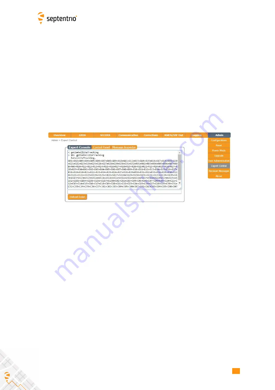
Commands can be sent to the AsteRx SB Sx using the

Expert Console

window on the

accessible via the

Admin

menu as shown in Figure 8-12

The command responses will be shown the window below the label

Expert Console

.

Clicking the up and down arrows of your keyboard will allow you to scroll through
previously entered commands

Speci

c messages may be viewed via the Message

I

nspector

The command set of the AsteRx SB Sx is described in the

Command Line

I

nterface

Reference Guide.pdf

Figure 8-12:

Web

I

nterface Admin-Expert Console

68

Summary of Contents for AsteRx SB Sx

Page 1: ...AsteRx SB Sx User Manual ...

Page 2: ...may not support functions specific to certain variants While we try to keep the manual as complete and up to date as possible it may be that future features functionality or other product specifications change without prior notice or obligation The information contained in this manual is subject to change without notice We recommend you to look for new or updated information in our Knowledge Base at...

Page 3: ... 3 3 Using the Ethernet cable 16 3 4 BASIC OPERATIONAL MONITORING 18 3 5 CONNECTING THE ASTERX SB SX TO THE INTERNET 20 3 5 1 Connecting the AsteRx SB Sx over WiFi 20 3 5 2 Connecting the AsteRx SB Sx over a network with internet access 22 4 PPP RTK out of the box 23 5 Configuring the AsteRx SB Sx as a Rover 24 6 Other receiver operations 30 6 1 SETTING THE ANTENNA HEIGHT 30 6 2 HOW TO CONFIGURE SB...

Page 4: ...F THE ASTERX SB SX 64 8 5 HOW TO CONFIGURE DYNAMIC DNS 66 8 6 HOW TO CONTROL ACCESS USING THE ASTERX SB SX FIREWALL 67 8 7 USING THE EXPERT CONSOLE 68 9 Security 69 9 1 HOW TO MANAGE ACCESS TO THE ASTERX SB SX 69 9 1 1 SSH key authentication 71 10 GIS Collection with PinPoint GIS or other applications 72 10 1 INTRODUCTION 72 10 2 USING THE ASTERX SB SX ON BOARD SIMPLE DATA COLLECTOR 73 10 2 1 Desi...

Page 5: ...ronmental compliance 1 1 3 Safety information Statement 1 The power supply provided by Septentrio if any should not be replaced by another If you are using the receiver with your own power supply it must have a double isolated construction and must match the specifications of the provided power supply Statement 2 Ultimate disposal of this product should be handled according to all national laws and...

Page 6: ...dedicated Support section http www septentrio com support where the User Manual the Firmware Reference Guide and the latest officially supported Firmware version are readily available for download Further information can be found on our website or by contacting Septentrio s Technical Support department In case the AsteRx SB Sx does not behave as expected and you need to contact Septentrio s Technica...

Page 7: ...P68 weatherproof housing AIM interference monitoring and mitigation system Bluetooth WiFi Ethernet Serial and USB communications 2 1 1 GNSS specifications 448 hardware channels to track the following supported signals GPS L1CA L1PY L2PY L2C L5 GLONASS L1CA L2P L2CA L3 Galileo1 E1 BC CBOC E5 a b AltBoc BeiDou1 B1 B2 SBAS EGNOS WAAS GAGAN MSAS SDCM L1 incl L5 tracking IRNSS1 L5 QZSS L1CA L2C L5 Integ...

Page 8: ...mental Size 102 x 36 x 111 mm 4 0 x 1 4 x 4 4 in Weight 460 g 1 01 lb Input voltage 5 to 36 V DC Power consumption 1 5 W typical Operating temperature 30 C to 65 C 22 F to 149 F Storage temperature 40 C to 75 C 40 F to 167 F Ingress Protection IP68 Humidity MIL STD810G Method 507 5 Procedure I Dust MIL STD 810G Method 510 5 Procedure I Shock MIL STD 810G Method 516 6 Procedure I II Vibration MIL S...

Page 9: ...AsteRx SB Sx design 2 2 1 Front Panel The AsteRx SB Sx has an intuitive front panel with status LEDs and a central power button Figure 2 1 The front panel of the AsteRx SB Sx Tables 2 2 1 below provides an overview of the LED indicators 9 ...

Page 10: ...ected Green On Connected Green Blinking Transferring data Positioning Mode Off No position can be calculated Green On The reported position is RTK Fixed or PPP RTK Yellow On SBAS DGPS or RTK Float Red On Stand alone Power Button Off Receiver is powered off White Receiver is booting Blue Power over Ethernet PoE powered Green VIN USB or OTG powered Function Button Off There is currently no functionality...

Page 11: ... 2 Rear Panel Figure 2 2 shows the layout of the rear panel connectors on the AsteRx SB Sx A description of the connector PIN layout and cable colour assignments can be found in Appendix A Figure 2 2 The rear panel of the AsteRx SB Sx 11 ...

Page 12: ...cro USB cable between the front panel of the receiver and either the recommended Septentrio USB adapter or the USB socket of a PC as shown in Figure 3 1 If the AsteRx SB was turned on before last power outage it will start up automatically otherwise press firmly on the power button Figure 3 1 Front panel power socket The AsteRx SB Sx can also be powered over Ethernet PoE as described in Appendix B ...

Page 13: ... web browser using the receiver s on board Web Interface The connection can be made over USB Ethernet or WiFi The following sections describe each of the connection methods 3 3 1 Using the micro USB cable Connect the micro USB cable to the front panel of the AsteRx SB Sx and to your PC as in Figure 3 3 Figure 3 3 Connecting to the front panel USB socket The first time that the USB cable is connecte...

Page 14: ...s recommended to unplug then re plug in the USB cable on your device to fully activate the drivers The USB connection on the AsteRx SB Sx functions as network adapter and the DHCP server running on the receiver will always assign the AsteRx SB Sx the IP address 192 168 3 1 To connect to the AsteRx SB Sx you can then simply open a web browser using the IP address 192 168 3 1 as shown in Figure 3 5 ...

Page 15: ...hat the WiFi modem is turned on On your PC or tablet search for visible WiFi networks the AsteRx SB Sx identifies itself as a wireless access point named AsteRx_SB serial number The serial number of the AsteRx SB Sx can be found on an identification sticker on the receiver housing Select and connect to the AsteRx SB Sx as shown in Figure 3 7 Figure 3 7 Select the AsteRx SB Sx from the list of detect...

Page 16: ...et For the most straightforward setup the RJ45 socket of the Ethernet cable should be connected to a network running a DHCP server The IP address assigned to the receiver will be associated with the hostname AsteRxSB xxxxxxx where xxxxxxx are the 7 digits of the AsteRx SB Sx serial number The serial number can be found on a WiFi identification sticker on the receiver housing You can then make a con...

Page 17: ...TED WITH THE ASTERX SB SX Figure 3 10 shows a screenshot of an Ethernet connection to an AsteRx SB receiver with serial number 3024596 using http asterxsb 3024596 Figure 3 10 Connecting to the Web Interface over Ethernet 17 ...

Page 18: ... tracking The temperature of the receiver board and the voltage supplied is also shown The icons to the right of the information bar show that in this example the position of the receiver is fixed the overall performance signal quality and CPU is Excellent 5 out of 5 bars and the receiver is logging to the internal disk The Corrections icon indicates that differential corrections are being sent out ...

Page 19: ...atellites from that particular constellation in tracking More information can be found in the Satellites and Signals page on the GNSS menu The Data Streams field gives an overview of the data streams into green lines and out from blue lines the receiver In this example the receiver is logging SBF data to the internal memory DSK1 and sending out RTCMv3 differential correction data over the IPS1 port ...

Page 20: ...SB Sx to a WiFi Access Point If you can connect to the receiver over WiFi using the Web Interface then it is already configured in Access Point mode The Access Point setting is the default configuration however if your receiver has been configured as a Client you can reconfigure it over USB To do this connect the AsteRx SB Sx to your PC using the micro USB cable You can now open an internet browser an...

Page 21: ... Interface using the USB connection You will not be able to connect using 192 168 20 1 Appendix D describes how to access the web interface once in Client WiFi mode configuration 1 Connect the Rover unit over a USB cable to your PC and connect to the web interface using 192 168 3 1 2 On the Communications WiFi window enable the Client WiFi mode and click on OK as shown in Figure 3 14 Figure 3 14 Wi...

Page 22: ...hernet connector or the USB connector OTG socket or rear panel USB connector of the AsteRx SB Sx When using Ethernet make sure your network has internet access Contact your system administrator to confirm that your network is a properly configured Extra settings are available on the Ethernet settings menu as explained in Section 8 4 Internet access can be enabled via USB RNDIS IP interface however t...

Page 23: ... needs to be turned on again this can be done in the Web Interface This is achieved by navigating to the SecoRx S menu and moving the slider to the on position as illustrated in Figure 4 1 and Figure 4 2 Figure 4 1 SecoRx S service reception turned off default Figure 4 2 SecorRx S service corrections being received Saving the current configuration to boot will make sure the receiver will connect the...

Page 24: ... the Rover general settings The AsteRx SB Sx can use correction data to calculate a cm level RTK position For the AsteRx SB Sx to operate as a Rover and accept differential correction data from a Base station check that Rover and RTK are selected in the Position Mode field in the GNSS menu as shown in Figure 5 1 This is the default operating mode of the AsteRx SB Sx Figure 5 1 Setting the AsteRx SB ...

Page 25: ...window of the Corrections menu you can configure the AsteRx SB Sx to only accept differential corrections of a particular format The default auto setting will accept correction data format RTCMv2 RTCMv3 or CMR Figure 5 2 With the default auto setting AsteRx SB Sx will accept RTCMv2 RTCMv3 or CMR format as incoming differential corrections Step 2 Configure internet connection Section 3 5 details how to...

Page 26: ... New NTRIP client as shown in Figure 5 3 Figure 5 3 NTRIP tab of the Web Interface 3 Enter the NTRIP caster details as shown in Figure 5 4 and click Ok The mount point list will only be populated when the caster details have been entered correctly and when you have an active internet connection Figure 5 4 NTRIP client mode settings 26 ...

Page 27: ...wered If the Mode Field is set to Off no corrections will be received and the AsteRx SB Sx will not auto connect to the Caster when switched on Step 3b Configure corrections using an IP connection Configure the IP connection of the Rover receiver Alternatively corrections can also be received using an IP connection in which case no internet connection is required but an IP connection to a Base statio...

Page 28: ...ed correctly then graphics in the Communication Ethernet windows of the Rover and the Base station should appear similar to those shown in Figures 5 7 and 5 8 Figure 5 7 Ethernet window of the Base station receiver showing an active output of RTCMv3 differential corrections on server port IPS1 Figure 5 8 Ethernet tab of the Rover receiver showing a fixed RTK position in the header and reception of R...

Page 29: ...THE ASTERX SB SX AS A ROVER Step 4 Configure data output Section 6 2 details the settings needed to configure data output Step 5 Configure any additional settings Chapter 6 details some additional settings that you may need 29 ...

Page 30: ... survey pole 1 Click on the GNSS Status tab and enter the antenna height 2 Click Apply when finished In the example shown in Figure 6 1 an offset of 2 0 meters was used Figure 6 1 GNSS Tab setting Antenna Offset By selecting the correct antenna type the AsteRx SB Sx will automatically compensate for the Antenna Phase Centre offset using the approved calibration of the product in order to provide the m...

Page 31: ... 4 detail how to log data on the receiver and how to download data logged on the receiver 6 2 1 Output over a serial COM connection The AsteRx SB Sx can be connected via a serial COM cable to an RS 232 compatible secondary device Step 1 Configure the serial COM port The COM port of the AsteRx SB Sx should be configured with the same baud rate and flow control setting of the coupled device These setti...

Page 32: ...n the NMEA SBF Out tab clicking on New NMEA Stream will guide you through the steps needed to configure NMEA output as shown in Figures 6 3 and 6 4 Figure 6 3 Selecting to output NMEA data on COM3 Figure 6 4 Selecting to output the GGA and ZDA NMEA message every second 32 ...

Page 33: ...t window a second output stream can be configured In the example shown in Figures 6 5 and 6 6 the PVTCartesian SBF data block will be output over COM1 once per second Figure 6 5 Selecting to output SBF data on COM1 Figure 6 6 Selecting to output the PVTCartesian SBF block every second 33 ...

Page 34: ...re 6 7 Figure 6 7 Summary of all configured data output streams Figure 6 8 shows the actual data output NMEA is in ASCII and is thus readable unlike SBF which is formatted in binary In this example the serial COM was connected to a PC via a USB adapter which maps the serial connection to a virtual COM9 of the PC Figure 6 8 Example showing output NMEA GGA left panel and SBF PVTCartesian right panel ...

Page 35: ...example shown in Figure 6 9 port 600 has been configured as connection IPS1 in TCP2Way mode so data can be received as well as transmitted over the connection When choosing a port number avoid conflicts with other applications such as the commands port 28784 the webserver port 80 the FTP port 21 as well as the default NTRIP port 2101 and the NTP port 123 Note that a new IP port can also be configured...

Page 36: ...e of windows to configure the data you want to output In the example shown in Figure 6 10 the NMEA GGA message will be output every second Ensure that the previously configured IPS1 port is selected for output as highlighted Figure 6 10 Select to output NMEA GGA over the configured IPS1 connection Similar steps can be followed to output SBF messages 36 ...

Page 37: ...the TCP IP Client button to configure the connection In the highlighted fields insert the IP address or hostname of the receiver and the port number configured in Step 1 Click on Connect Figure 6 11 Configure the TCP IP connection settings in Data Link The info line at the bottom of the window should indicate that a connection has been made Click on the Show Data button to display the GGA data from th...

Page 38: ...CHAPTER 6 OTHER RECEIVER OPERATIONS Figure 6 12 The Show data window of Data Link showing GGA from the AsteRx SB 38 ...

Page 39: ...e of your AsteRx SB Sx and pair By default the Bluetooth device name is AsteRx_SB serial number The device name and pairing code may be changed for user preference Also the Bluetooth module may be powered on off and set to discoverable from this tab It is however advised to leave the Discoverable option switched on Figure 6 13 Configuring the Bluetooth connection to an external device Step 2 Configur...

Page 40: ...n the memory is full or it continues logging by making space for new files by deleting the oldest The default setting is Stop logging in all sessions Figure 6 14 Selecting what you wish to happen when the internal 16 GB memory is full Step 2 Configuring a logging session On the Log Sessions window of the Logging menu you can check which logging sessions have already been defined and define new ones Up...

Page 41: ...according to IGS convention but files can also be freely named using either Filename or Incremental options In this example the default settings of Internal Disk and Never for Auto Delete2 have been selected In the Edit SBF Stream window the messages required for RINEX generation have been selected as well as those useful for the Support department for diagnosing problems SBF messages can also be s...

Page 42: ... session the Log Sessions window will show a summary of the defined logging sessions as in Figure 6 17 An estimate of the daily size of data generated with the current logging configuration is also given Figure 6 17 A summary of the newly defined logging sessions showing the expected amount of data generated daily 42 ...

Page 43: ...ormatting is not compatible with the receiver file system you will be prompted to format the device This can be done by clicking on the Format button as shown in Figure 6 18 Figure 6 18 With a 2 GB external USB memory device connected to the AsteRx SB New logging sessions can then be defined in a similar way as in Section 6 3 1 making sure to select External from the drop down list in the Disk field ...

Page 44: ...ernal USB device can be downloaded using the web interface on the Disk Contents window of the Logging menu Each logging session is logged to a separate folder Individual files can be downloaded by clicking on the green download arrow next to the file name as shown in Figure 6 20 Obsolete files can be deleted by clicking the Figure 6 20 Downloading logged files 44 ...

Page 45: ...receiver will retry after the Retry Interval which has been selected as 15 minutes in this example Figure 6 21 Configure pushing of RINEX files to an external FTP server You can check that the FTP server credentials are correct by clicking on the Test button This will push a small test file to the remote folder and then delete it The receiver reports whether or not the file was successfully sent and d...

Page 46: ...CHAPTER 6 OTHER RECEIVER OPERATIONS Figure 6 22 Testing the remote FTP server credential are correct 46 ...

Page 47: ...e The effects of wideband interference both intentional and unintentional can be mitigated by turning on the WBI mitigation system The WBI system also reduces more effectively than traditionally used pulse blanking methods the effects of pulsed interferers The spectrum view plot In the Spectrum window of the GNSS menu you can monitor the RF spectrum and configure three separate notch filters to cancel ...

Page 48: ...own configured for Notch1 in Figure 7 2 the region of the affected spectrum is specified by a center frequency and a bandwidth which is effectively blanked by the notch filter Figure 7 2 Configuring the first notch filter Notch1 at 1235 MHz With the Notch1 settings as shown in Figure 7 2 the L2 band after the notch filter After IM is shown in Figure 7 3 with the blanked section clearly visible Figure 7 3 T...

Page 49: ...n reduce the effect of both types of interference on GNSS signals Configuring WBI mitigation The wideband interference mitigation system WBI can be enabled by selecting on as shown in Figure 7 4 Figure 7 4 Select on to enable wideband interference mitigation then OK to apply the new setting WBI mitigation in action The GPS L1 band interference shown in Figure 7 5 is produced by combining the GNSS an...

Page 50: ...is clearly visible as Figure 7 6 shows In this particular test the interference signal caused the receiver to fall back to the less precise DGNSS or standalone positioning modes With WBI mitigation enabled however the receiver was able to maintain an RTK fix position throughout Figure 7 6 Enabling WBI interference mitigation greatly reduces the effect of the interference caused by the chirp jammer 5...

Page 51: ...ging session Figure 7 7 Click on a Create button to start defining a new logging session Step 2 Select to log the Support data blocks In the Edit Session click on SBF and New SBF stream In the final Edit SBF Stream field make sure to select the Support option as shown in Figure 7 9 This option automatically selects all the SBF blocks that are useful for the Support Department to help diagnose receive...

Page 52: ...the Edit SBF Stream field Figure 7 9 Selecting BBSamples in the Edit SBF Stream field for logging interference Please note that logging the Support data blocks requires a large throughput of data that may not be compatible with other CPU intensive tasks such as data output at higher rates 52 ...

Page 53: ... as indicated in Figure 7 10 Figure 7 10 The Logging window showing an active logging session Step 3 Downloading the logged SBF file To download a data file logged on the AsteRx SB Sx click the download icon next to the filename on the Disk Contents page as shown in Figure 7 11 Figure 7 11 Click the icon next to the file you want to download 53 ...

Page 54: ...CEIVER MONITORING 7 2 2 Diagnostic Report A Diagnostic Report can be generated under the Admin About tab on the Web interface as shown in Figure 7 12 and saved to your PC Figure 7 12 Generate a Diagnostic Report 54 ...

Page 55: ...in the Receiver Messages window of the Admin menu that can be used to check receiver operations The example in Figure 7 13 shows that four 15 minutes SBF files have been successfully FTP pushed to a remote location Figure 7 13 Events reported by the AsteR SB in the Receiver Messages window 55 ...

Page 56: ...fault configuration Current No Yes Settings that are actually being used Boot Yes Yes The receiver configuration on start up User1 User 2 Yes Yes Two configurations can be stored for later use With the Web Interface you can perform the following operations on configurations Copy The Copy operation allows the user to copy any of the five configurations into another configuration Download The Download oper...

Page 57: ...ction 8 1 2 for more information on managing configurations Figure 8 1 The save to Boot pop up If you have consistently pressed Save when the pop up appears on the screen all settings will be persistent and will be applied again when the device powered on You can also save the current configuration as the boot configuration on the Admin Configurations window as shown in Figure 8 2 Select Current and B...

Page 58: ...be copied in the Source drop down box 2 Select where the Source configuration is to be copied into using the Target drop down box 3 Click OK Download Configuration 1 Click the next to the configuration to be downloaded 2 The download is started immediately 3 The configuration will be saved as a txt file in the browser s download folder Upload Configuration 1 Click the next to the configuration to be uplo...

Page 59: ... either Current or Boot in the Target menu You will then be prompted to Save or Ignore the new current configuration as the boot configuration Figure 8 4 Setting the AsteRx SB Sx to the default configuration Please note that this procedure will not erase the IP settings of the receiver This can only be done on the Ethernet page of the Communication menu In case of configuration reset the PPP RTK corre...

Page 60: ...ividually reset as shown in Figure 8 5 The reset options are described in Tables 8 2 1 and 8 2 2 Figure 8 5 Admin Reset Level Description Soft This is a reset of the receiver s firmware The receiver will restart operating in the same configuration as before the command was issued unless the Config option has been ticked Hard This is similar to a power off on sequence After hardware reset the receiver ...

Page 61: ...ased SatData All satellite navigation data ephemeris almanac ionosphere parameters UTC stored is erased BaseStations All Base stations stored are erased Bluetooth All information about previously known Bluetooth devices is erased WiFiAccessPoints The list of known WiFi access points is erased HTTPSCertificate The current HTTPS certificate is removed and will be replaced by self signed certificate at ...

Page 62: ...ware upgrade beforehand in case there are any changes that may affect your use of the receiver Permission files enable additional features on the AsteRx SB Sx and can be purchased via our Sales department On the Admin menu select Upgrade and then click the Choose file button You can then select the upgrade suf file For major upgrades two or more files may have to be upgraded separately The files to be u...

Page 63: ...ure 8 7 The AsteRx SB Sx upgrade procedure If there were no problems with the upgrade the message Upgrade successful will appear You can then check on the Admin About tab that the AsteRx SB Sx firmware or permission file has the correct new version 63 ...

Page 64: ...parameters command shows the current ip configuration available and can be helpful for debugging network issues In Static mode the receiver will not attempt to request an address via DHCP but will use the specified IP address netmask gateway domain name and DNS DNS1 is the primary DNS and DNS2 is the backup DNS In DHCP mode the arguments IP Netmask Gateway Domain DNS1 and DNS2 are ignored Figure 8 8...

Page 65: ...ER ADMINISTRATION OPERATIONS Note that the IP settings will keep their value after a power cycle and even after a reset to factory default in order to avoid accidentally losing an Ethernet connection to the receiver 65 ...

Page 66: ...Sx you should first create an account with a Dynamic DNS provider to register a hostname for your receiver The AsteRx SB Sx supports the following two services Dyn DNS http dyn com No IP http www noip com Having opened account you can then create a host service for which you will need to specify a URL or hostname for the receiver e g axsb ddns net Step 2 Configure the Dynamic DNS settings of the rec...

Page 67: ...he IP Ports menu In the example shown in Figure 8 11 Ethernet ports 2101 2102 and 2103 are accessible but only from devices with the IP address 84 199 9 148 Similarly all WiFi ports are open but only those from IP 84 199 9 148 Please note that the firewall settings do not apply when connecting to the web interface using USB In the case of WiFi firewall settings only apply when the receiver is in WiF...

Page 68: ...re 8 12 The command responses will be shown the window below the label Expert Console Clicking the up and down arrows of your keyboard will allow you to scroll through previously entered commands Specific messages may be viewed via the Message Inspector The command set of the AsteRx SB Sx is described in the Command Line Interface Reference Guide pdf Figure 8 12 Web Interface Admin Expert Console 6...

Page 69: ...ir access level For added security an SSH key can be used This is described in Section 9 1 1 In the example shown in Figure 9 2 Web Interface Anonymous users without password can connect to the receiver via the web interface as Viewers They can browse the various windows but cannot change any of the settings Only George who has User access can change receiver settings via the web interface FTP Ano...

Page 70: ...efining user access After defining the Users Viewers and their access levels they can then login on the web interface by clicking on Log in on the upper right corner as shown in Figure 9 3 Figure 9 3 Logging in to the Web Interface 70 ...

Page 71: ...rd provided of course that the matching private key is known by the key agent running on the same PC You can generate public and private keys using for example PuTTY Key Generator as shown in Figure 9 4 Figure 9 4 Generating SSH keys using the PuTTY Key Generator The public key is highlighted The generated public key is the highlighted text that can be pasted directly into the SSH Key field of the ...

Page 72: ...independent of any GIS tool set allowing you to store data into CSV files PinPoint GIS is an extension of Septentrio s web interface with a direct link to ArcGIS Online via PinPoint GIS Web and with a generic on board data collection mechanism for any GIS workflow thanks to PinPoint GIS Rx not linked to ArcGIS accounts It offers a unique solution with the power to run GIS collection inside Septentrio...

Page 73: ...nnected to the internet and the receiver should have the Data Collection permission option 10 2 1 Designing a collection project On the GNSS menu of the Web Interface select PinPoint GIS Web click on PinPoint GIS Rx to select and to edit a collection project There are three collection projects that can be configured Select the project you want to edit and click Manage then Designer 73 ...

Page 74: ...ser defined attribute Fill in the name of the attribute and default value you want it to take Adding a receiver output attribute Click on New attribute again then select Receiver This will generate a drop down list from which you can select the receiver data output that you want to collect When all attributes have been added click on Save and close the project design window 74 ...

Page 75: ...n the Manage button next to the project you want to use You can then click on the Collector button to start a collection At each collection point click on collect and enter the details of the user defined attribute then click Save When the collection is finished you can click on Close to close the collection window Please note that points cannot be collected at more than 1 point per second 75 ...

Page 76: ...b click on PinPoint GIS Rx and then the Manage button next to the project you want download The project window will pop up where you can click on the CSV Export button In the export pop up window enter a name for the file and select the column separator Click on Export to generate the file and then on Download The file can be opened in Excel or any text editor 76 ...

Page 77: ...s view you have full access to your ArcGIS Online user maps The system allows you to select your ArcGIS Online user maps change the background of your user map using the multiple Basemaps available from Esri Display or hide the different layers and filters of your map and will allow you to have configurability for Portal for ArcGIS in the case your data is located in a specific secured ArcGIS Server N...

Page 78: ...CHAPTER 10 GIS COLLECTION WITH PINPOINT GIS OR OTHER APPLICATIONS Figure 10 8 Functions within PinPoint GIS Web 78 ...

Page 79: ... 1 3A Pink wire with Red heat shrink tube 2 Black GND GND Ground Brown wire with Black heat shrink tube 3 Green RxD3 USB D EITHER Serial COM3 receive line OR Negative USB 2 0 FS device node Selection is done via pin 7 4 Yellow TxD3 Not connected Serial COM3 transmit line 5 Grey RxD2 USB D EITHER Serial COM2 receive line OR Positive USB 2 0 FS device node Selection is done via pin 7 6 White TxD2 No...

Page 80: ...etection 1 µs 15 KΩ pull down 2 Black GND Ground Brown wire with Black heat shrink tube 3 Green COM1 CTS EVENTB COM1 Clear to Send This also connects to the second event EVENTB input It has the same electrical specifications as EVENTA see pin 1 4 Yellow COM1 RTS PPS_OUT COM1 Request To Send or PPS_OUT PPS_OUT low 0V PPS_OUT high 5V PPS_OUT polarity is consistent with command line reference of OEM m...

Page 81: ...o this connector The gain at the connector antenna gain minus cable losses must be in the range 15 to 50dB By default the receiver provides a 3 3V DC supply on the MAIN connector to feed the antenna The supplied antenna voltage can be changed to 5V DC with the command setAntennaVoltage The maximum supported current is 200mA Never inject a DC voltage into the MAIN connector as it may damage the rec...

Page 82: ...r is supplied through USB together with any other supply Ethernet or PWR USB is always used as backup power supply For delivering power through USB both USB ports are considered equal If the receiver is supplied from a voltage source 5 5V The USB OTG port is only usable as USB device not as USB host No power should be drawn from the 5V OUT pin of the COM1 GPIO connector When powered via Ethernet t...

Page 83: ...f the top banner quickly show the user the status of the AsteRx SB Sx Table C 1 1 Web Interface Status Icons 1 By default the Internet access is continuously checked every 1 minute and one of the icons will show up The check can be enabled or disabled with the command setCheckInternetAvailability When this setting is disabled the icons will disappear 83 ...

Page 84: ... the mobile connection of your mobile device and the way to connect to the web Interface 1 Make sure your mobile device has been configured with personal hotspot a user and a password will be displayed to the user 2 Plug the USB cable of the Rover unit and connect to the web interface using 192 168 3 1 3 On the Communications WiFi window enable the Client WiFi mode and click on OK as shown in Figur...

Page 85: ...rowser Where xxxxxxx is the 7 digit serial number of the receiver Android and Windows devices To access web interface you need to know the IP address assigned to the receiver by your mobile device Most Android devices allow you to see the assigned IP address within the network settings Alternatively you can connect to the receiver using USB in order to find the IP address assigned to the receiver d...

Reviews: