12
12
AsteRx-m3 OEM
12
2.5.2
60-pin connector
Connector type: Hirose DF40C-60DP-04V(51)
Mating connector: Hirose DF40HC(3.5)-60DS-0.4V(51)
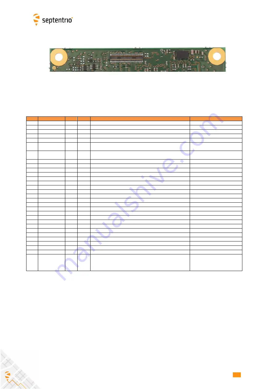
See the pin numbering convention in the above picture.
Pin#
Name
Type
Level
Description
Comment
1
Reserved
3
Reserved
5
Reserved
7
Reserved
9
GP1
O
LVTTL
General purpose output. GP1 in
setGPIOFunctionality
command.
See section 2.9
11
RTS2
O
LVTTL
Serial COM2 RTS line. The AsteRx-m3 drives this pin low when ready
to receive data.
13
RTS3
O
LVTTL
Serial COM3 RTS line. The AsteRx-m3 drives this pin low when ready
to receive data.
15
TX4
O
LVTTL
Serial COM 4 transmit line (inactive state is high)
17
Reserved
19
Reserved
21
Reserved
23
Reserved
25
Reserved
27
Reserved
29
GND
Gnd
Ground
31
RMII_TXEN
O
LVTTL
LAN PHY transmit enable
See section 2.13
33
RMII_TXD1
O
LVTTL
LAN PHY transmit data 1
See section 2.13
35
RMII_CRS_DV
I
LVTTL
LAN PHY CRS
See section 2.13
37
RMII_RXER
I
LVTTL
LAN PHY RX error
See section 2.13
39
Reserved
41
Reserved
43
Reserved
45
Reserved
47
Reserved
49
Reserved
51
Reserved
53
Reserved
55
Reserved
57
EventB
I,PD
LVTTL
Event B input.
See section 2.8
59
IO_EN
O
LVTTL
Level is high when board is in normal operating conditions and it is
safe to drive the input pins (see also warnings in section 2.10). This
pin becomes high no later than 300 ms after power up or wake up
from standby.
2
59
1
60


