background image

U1

V1

W1

N

U2

V2

W2

N

PE

PE

EN

Installation instructions, only for experts 

p. 19/28

Connection of Concept R 12 kW and 15 kW  
(CP-RB-120 / CP-RB-150)

1.  Guide the connection cable for the sauna control unit through the feed-

through 

8

.

2.  Connect the connectors of this connection cable to the U1 – V1 – W1 – N – PE 

terminals on the connector block 

9

 and to the applicable sauna control unit 

terminals. Observe the installation instructions for the sauna control unit when 
doing so.

3.  Guide the booster cable through the feed-through 

7

.

4.  Connect the connectors of the booster cable to the U2 – V2 – W2 – N – PE 

terminals on the connector block 

6

 and to the applicable booster terminals. 

Observe the installation instructions of the booster when doing so.

5.  Reattach the cover panel 

2

 to the heater.

6

7

9

8

6

 Connector block for the booster

7

 Feed-through for the booster cable

8

 Connector block for the sauna control unit

9

 Feed-through for the connection cable for the sauna control unit

Summary of Contents for 1-027-768

Page 1: ...CTIONS FOR INSTALLATION AND USE English Sauna heater Concept R black CP RB 090 1 027 768 Concept R 9 0 kW black CP RB 105 1 027 769 Concept R 10 5 kW black CP RB 120 1 027 770 Concept R 12 0 kW black CP RB 150 1 027 771 Concept R 15 0 kW black ...

Page 2: ...Accessories 9 3 3 Product functions 9 4 Installation and connection 10 4 1 Installation location and sensor position 10 4 2 Safety distances 11 4 3 Adjusting the height 12 4 4 Connection diagram for 400 V 3N 13 4 5 Connection diagram for 230 V 1N 15 4 6 Wiring diagrams 16 4 7 Electrical connection 18 5 Commissioning 20 5 1 Filling the stone container 20 HDWLQJ IRU WKH UVW WLPH 21 6 Operation 22 6 ...

Page 3: ...EN 7 Maintenance 23 7 1 Extended periods of non use 23 7 2 Cleaning the sauna heater 23 7 3 Changing the sauna stones 23 8 Disposal 24 9 Problem solving by the installer 25 10 Technical data 26 ...

Page 4: ...ge to property and injuries which in the worst case may be fatal The warning notices contain keywords which have the following meanings DANGER Serious or fatal injury will occur if this warning notice is not observed WARNING Serious or fatal injury can occur if this warning notice is not observed CAUTION Minor injuries can occur if this warning notice is not observed ATTENTION This keyword is a wa...

Page 5: ... a remote start function but only in conjunction with the optional safety shutdown feature CP R SWL The Concept R sauna heater can also be used in public saunas but only in conjunction with the optional safety shutdown feature CP R SWL Any use exceeding this scope is considered improper use Improper use can result in damage to the product severe injuries or death 2 2 Safety information for the ins...

Page 6: ...If other materials than wood are used in the sauna cabin these materi als must be heat resistant and corrosion resistant and must not cause any negative effects on the health of the sauna users Ɣ The height of the sauna cabin must be at least 2 0 m Ɣ 2EVHUYH WKH VSHFL FDWLRQV RQ YROXPHV DQG RQ YHQWLODWLRQ RI WKH sauna cabin in chapter 10 Technical data Ɣ When positioning the sauna heater observe t...

Page 7: ... persons with lack of experience knowledge under the following conditions They are supervised They have been shown how to use the device safely and are aware of the hazards that could occur Ɣ Children must not play with the device Ɣ Children under 14 years of age may only clean the device if they are supervised Ɣ RU KHDOWK UHDVRQV GR QRW XVH WKH VDXQD ZKHQ XQGHU WKH LQÀX ence of alcohol medication...

Page 8: ...g the VDXQD IRU WKH UVW WLPH R 127 UHPDLQ LQ WKH VDXQD FDELQ GXULQJ this period Then ventilate the sauna cabin well see 5 2 Heating IRU WKH UVW WLPH on page 21 Ɣ Never touch the sauna heater while it is operating The surfaces of the sauna heater and sauna stones become extremely hot Ɣ For your own safety consult your supplier in the event of problems WKDW DUH QRW GHVFULEHG LQ VXI FLHQW GHWDLO LQ W...

Page 9: ...R L2 WALNUT wooden railing small 9 10 5 kW CP R N1 WALNUT wooden railing large 12 15 kW CP R N2 Emotion railingset LINDEN small 9 10 5 kW CPR EMO L1 Emotion railingset LINDEN large 12 15 kW CPR EMO L2 Emotion railingset WALNUT small 9 10 5 kW CPR EMO N1 Emotion railingset WALNUT large 12 15 kW CPR EMO N2 Power booster O S2 18 O S2 18S O S2 30 3 3 Product functions The Concept R sauna heater is a F...

Page 10: ... Ɣ The Concept R sauna heater is a free standing heater It does not need to EH DWWDFKHG WR WKH ÀRRU RU VDXQD ZDOO Ɣ R QRW SODFH WKH VDXQD KHDWHU RQ D ÀRRU PDGH IURP DQ HDVLO ÀDPPDEOH PDWHULDO VXFK DV ZRRG RU SODVWLF 6XLWDEOH ÀRRULQJ LQFOXGHV FHUDPLF WLOHV IRU example 4 1 Installation location and sensor position Position the heater centrally in front of the air intake opening in the cabin wall 2EV...

Page 11: ... EN Installation instructions only for experts p 11 28 Fig 1 Safety distances for Concept R 9 kW and 10 5 kW CP RB 090 CP RB 105 Measurements in mm CP RB 090 CP RB 105 4 2 Safety distances 2EVHUYH WKH PLQLPXP VDIHW GLVWDQFHV VSHFL HG LQ Fig 1 and Fig 2 ...

Page 12: ...e Concept R sauna heater has height adjustable feet The height can therefore be set between 715 mm and 725 mm Each foot can be set individually making LW SRVVLEOH WR DGDSW WKH VDXQD KHDWHU WR XQHYHQ ÀRRUV 1 Loosen the sauna heater foot using an open ended spanner 13 mm 2 Lift the sauna heater slightly and turn the foot to the right to reduce the height Turn to the left to increase the height 3 Ret...

Page 13: ...tructions only for experts p 13 28 4 4 Connection diagram for 400 V 3N Fig 3 Connection diagram for Concept R 9 kW and 10 5 kW CP RB 090 CP RB 105 2 3 4 1 Sauna control unit 2 Temperature sensor with excess temperature cut out 3 Sauna heater 9 kW or 10 5 kW 4 Power supply 1 ...

Page 14: ... V 3x35 A N ST3 Installation instructions only for experts p 14 28 Fig 4 Connection diagram for Concept R 12 kW and 15 kW CP RB 120 CP RB 150 1 2 3 4 5 6 1 Sauna control unit 2 Temperature sensor with excess temperature cut out 3 Concept R sauna heater 12 kW or 15 kW 4 Sauna control unit power supply 5 Power booster 6 Booster power supply A12 kW and 15 kW ...

Page 15: ...nly for experts p 15 28 4 5 Connection diagram for 230 V 1N Connection diagram for Concept R 9 kW and 10 5 kW CP RB 090 CP RB 105 Fig 5 1 Sauna control unit 2 Temperature sensor with excess temperature cut out 3 Sauna heater 9 kW or 10 5 kW 4 Power supply Remove the copper bridge 1 4 3 2 ...

Page 16: ... kW 1 5 kW 1 5 kW U V W 1 5 kW 1 5 kW 1 5 kW CP R 090 9 0 kW N N N W V U 4 6 Wiring diagrams 1 5 kW 2 0 kW 1 5 kW U V W 2 0 kW 1 5 kW 2 0 kW CP R 105 10 5 kW N N N W V U To the sauna control unit To the sauna control unit CP RB 090 9 0 kW CP RB 105 10 5 kW ...

Page 17: ... 5 kW 1 5 kW 1 1 kW N V2 1 5 kW 1 5 kW 1 1 kW U2 W2 To the sauna control unit To the power booster 1 5 kW 1 5 kW 2 0 kW U1V1W1 N CP R 150 15 0 kW 1 5 kW 1 5 kW 2 0 kW N V2 1 5 kW 1 5 kW 2 0 kW U2 W2 To the sauna control unit To the power booster 9 kW 3 3 kW 9 kW 6 kW CP RB 120 12 0 kW CP RB 150 15 0 kW ...

Page 18: ...of the connection cable to the U V W N PE terminals of the sauna heater and to the applicable sauna control unit terminals Observe the installation instructions for the sauna control unit when doing so 3 Reattach the cover panel 2 to the heater 4 7 Electrical connection 1 Unscrew the screws 3 and 4 with a screwdriver 2 Unscrew the screws 1 and 5 with a screwdriver 3 Remove the cover plate 2 6 1 2 ...

Page 19: ...nals Observe the installation instructions for the sauna control unit when doing so 3 Guide the booster cable through the feed through 7 4 Connect the connectors of the booster cable to the U2 V2 W2 N PE terminals on the connector block 6 and to the applicable booster terminals Observe the installation instructions of the booster when doing so 5 Reattach the cover panel 2 to the heater 6 7 9 8 6 C...

Page 20: ...J WKH KHDWHU ZLWK WKH VDXQD VWRQHV FKHFN WKHP IRU IRUHLJQ REMHFWV and remove any remaining packaging 3 Place the stones in the stone container Stack the sauna stones loosely so WKDW DLU FDQ ÀRZ WKURXJK WKH JDSV 4 Make sure that the sauna stones do not protrude beyond the edge of the stone container WARNING 5LVN RI UH GXH WR RYHUKHDWLQJ If the sauna heater is used without sauna stones the cabin wal...

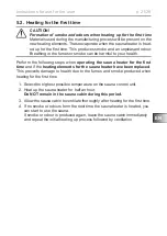
Page 21: ...HDWHU IRU WKH UVW time and if the heating elements for the sauna heater have been replaced This prevents damage to health due to the fumes and smoke produced when KHDWLQJ IRU WKH UVW WLPH 1 Select the highest possible temperature on the sauna control unit 2 Heat up the sauna heater for half an hour Do NOT remain in the sauna cabin during this period 3 OORZ WKH VDXQD FDELQ WR YHQWLODWH WKRURXJKO DI...

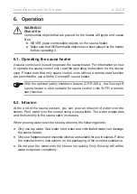
Page 22: ...a heater 6 2 Infusion At the end of the sauna session you can pour an infusion of water over the stones Pour water over the stones using a sauna ladle The water evaporates and the humidity in the sauna cabin increases When pouring water over the stones observe the following points Ɣ Only use tap water Sea water hard water and chlorinated water can damage the sauna heater Ɣ Only use fragrances and ...

Page 23: ... on the heating rods during ex tended periods of non use 7 2 Cleaning the sauna heater Make sure that the ventilation openings are free of lint and dust This prevents the air circulation in the sauna heater from being restricted and prevents the device from overheating 7 3 Changing the sauna stones Sauna stones are subject to stress by the water poured on them and by large ÀXFWXDWLRQV LQ WHPSHUDWX...

Page 24: ...y applicable regulations 1 Remove the old sauna stones 2 Clear the stone container of limescale deposits dust and other contamination 3 Wash the stones thoroughly using water and a brush before use Do not use any cleaning additives 4 HIRUH OOLQJ WKH KHDWHU ZLWK WKH VDXQD VWRQHV FKHFN WKHP IRU IRUHLJQ REMHFWV and remove any remaining packaging 5 Place the stones in the stone container Stack the sau...

Page 25: ...r certain circumstances accumulation of moisture in the heating rods can lead to the FI circuit breaker being triggered In this case it is necessary to bake out the sauna heater under the supervision of an electrician To do this the protective function of the FI circuit breaker must be switched off The baking out procedure takes approximately 10 minutes The safety function of the FI circuit breake...

Page 26: ...50 x 70 40 CP RB 150 15 0 18 25 350 x 90 40 Item number Stone weight kg Fuse A Supply voltage CP RB 090 approx 25 3 x 16 400 V AC 3N 50 60 Hz 230 V AC 1N 50 60 Hz CP RB 105 approx 25 3 x 16 400 V AC 3N 50 60 Hz 230 V AC 1N 50 60 Hz CP RB 120 approx 35 3 x 16 3 x 10 400 V AC 3N 50 60 Hz CP RB 150 approx 35 3 x 16 3 x 10 400 V AC 3N 50 60 Hz Item number Heating rods CP RB 090 6 x SCA150 1 028 518 CP...

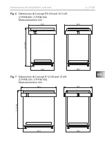
Page 27: ...63 446 715 725 519 450 523 EN Instructions for installation and use p 27 28 Fig 6 Dimensions of Concept R 9 kW and 10 5 kW CP RB 090 CP RB 105 Measurements in mm Fig 7 Dimensions of Concept R 12 kW and 15 kW CP RB 120 CP RB 150 Measurements in mm ...

Page 28: ...NOTIZEN APPUNTI NOTES NOTE NOTITIES ...

Reviews: