background image


Sentera 

PHX Unmanned Aircraft Pilot User Guide


www.sentera.com 

Page 73 

March 19, 2020 

844.SENTERA 


 © 2020 Sentera Inc. All rights reserved. 


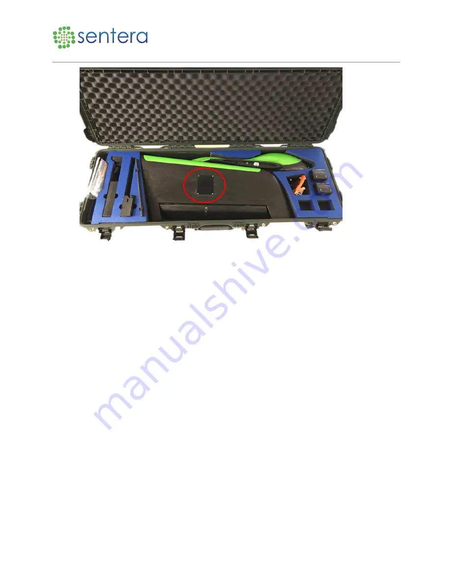
Figure 95: Servo Cover 

2. 

Carefully remove the air speed sensor using the #1 Philips screwdriver with tubes and wires 

attached.  

3. 

Remove the electrical cable and the pneumatic tubes.  

4. 

Trim the used ends of the pneumatic tubing off.  

5. 

Plug the electrical cable and pneumatic tubes into the replacement air speed sensor into the same 

ports. Attach the tubing to the air data sensor, as shown in Figure 96. 

Summary of Contents for PHX

Page 1: ...Sentera PHX Unmanned Aircraft Pilot User Guide Engineered in Minneapolis MN USA March 19 2020 Rev 1 3 ...

Page 2: ... Velcro Brand is the registered trademark or trademarks of Velcro Companies Third Party Content Products and Services Disclaimer This software and documentation may provide access to or information on content products and services from third parties Sentera is not responsible for and expressly disclaim all warranties of any kind with respect to third party content products and services Sentera wil...

Page 3: ...Fly PHXSoftware Crash or Lock Up 9 3 3 Lost Link 9 3 3 1 Aircraft Autonomous Behavior During Lost Link 9 3 4 Aircraft Autonomous Behavior During Lost GPS 9 3 5 Other Emergencies 10 3 6 Medical 10 3 7 Incident Reports 10 4 Application Settings 10 4 1 General Settings 10 4 2 Offline Maps Settings 13 4 3 Sentera FieldAgent 17 5 Normal Procedures 18 5 1 Flight Plan in Fly PHX 18 5 1 1 Create Flight Pl...

Page 4: ...eristics 50 7 Weight and Balance 50 7 1 Weight 50 7 2 Center of Gravity 51 8 System Description 52 8 1 Aircraft Description 52 8 2 Aircraft Sensors 53 8 3 Kit Contents 53 8 4 Field Support Kit Description 54 9 Handling Service and Maintenance 54 9 1 Battery Charge 54 9 2 Battery Care and Maintenance 58 9 2 1 Best Practices for Charge 58 9 2 2 Storage Recommendations 58 9 2 3 Expected Lifespan 59 9...

Page 5: ...ement 76 10 Supplements 76 10 1 Connecting to the CommsBox 76 10 2 Sentera Double 4K Payloads 77 10 2 1 Mapping Payload 78 10 2 2 Camera Information 78 10 3 Battery Swap Procedure 79 11 Safety Tips 83 11 1 Battery Use Precautions 83 11 2 Prohibited Maneuvers 83 11 3 Propeller Safety Precautions 83 12 Glossary 84 12 1 UAS Terms 84 12 2 Aircraft Terms 84 12 3 Aviation Terms 85 12 4 User Interface Te...

Page 6: ...ess datalink The PHX UAS can be fitted with a number of sensor payloads for precision agriculture survey mapping and public safety applications 1 1 Three View Drawing The PHX has a 54 inch wingspan as shown in Figure 1 Figure 1 PHX 3 View Drawing 2 Limitations The operator must ensure the system is operated within limits The autopilot and Fly PHX software have some built in checks that aid the ope...

Page 7: ...Maximum density altitude 14 000 ft 4300 m MSL mean sea level Maximum altitude above ground Flight operations must remain below the maximum altitude allowed by local regulations or local airspace authority Often this means below 400 ft 120 m AGL height above ground 2 3 Wind Limits The PHX UAS has recommended operating limits depending on wind speeds as shown in Table 3 Wind Limits Table 3 Wind Limi...

Page 8: ...mit Temperature Minimum 40 F 4 C Maximum 90 F 32 C 2 7 Battery Level Limits The following table describe the various battery limits as shown in Table 5 Battery Limits Table 5 Battery Limits Battery Level Limit Volts Maximum voltage 12 6 volts Nominal voltage 11 1 volts Minimum voltage 9 0 volts Warning Battery will be damaged if discharged below 9 0 volts during operation or if left in storage for...

Page 9: ...reforming the launch Figure 2 Take Off and Landing Limits 3 Emergency Procedures The following section describes emergency procedures for the operator and autonomous failsafe behaviors of the Unmanned Aircraft Vehicle UAV 3 1 Loss of Propulsion If propulsion power is lost the aircraft will automatically continue to fly the pre planned waypoints while gliding to the ground Maintain visual contact w...

Page 10: ...radio frequency line of sight Check that the ground radio is powered Check cable or wireless connections between CommsBox and computer tablet 3 3 1 Aircraft Autonomous Behavior During Lost Link If communications are not re established within the time out period typically 30 seconds the aircraft will automatically Return to Land RTL If communications are regained the operator may command the aircra...

Page 11: ...ent reports should be logged and applicable authorities notified as required Any incidents pertaining to the performance of the aircraft or other parts of the system should be reported to the manufacturer Telemetry logs files from the ground station payload and aircraft may be required to send to the manufacturer 4 Application Settings The Application Settings are used to set the general settings ...

Page 12: ...ge 11 March 19 2020 844 SENTERA 2020 Sentera Inc All rights reserved Figure 6 Application Settings 2 Click General to set the units miscellaneous data persistence telemetry logs from vehicle RTK GPS a server video and video recording as shown in Figure 7 and Figure 8 ...

Page 13: ...Sentera PHX Unmanned Aircraft Pilot User Guide www sentera com Page 12 March 19 2020 844 SENTERA 2020 Sentera Inc All rights reserved Figure 7 Units Miscellaneous and Data Persistence ...

Page 14: ...s reserved Figure 8 Fly View RTK GPS ADSB Server Video and Video Recording 4 2 Offline Maps Settings Map backgrounds in Fly PHX works best over a good internet connection Where internet connections may be unreliable unavailable it is recommended to pre load maps before heading out to the field using the Offline Maps window ...

Page 15: ...ne Maps under the Application Settings window There may be situations in the field where the UAS cannot connect to the satellites to provide a flight mission To get around this situation download a map to use offline 1 Click Offline Maps then click Add New Set as shown in Figure 9 The Add New Set window displays Figure 9 Offline Maps 2 Enter the name of the offline map in the Name field as shown i...

Page 16: ...3 Select the Map type 4 Adjust the zoom level if necessary Recommended values are 5 and 15 respectively 5 Click Download and then click Export 6 Select the map you just created and then click Export 7 You can also import a map from the Offline Maps window 8 Click Options to adjust the offline maps as shown in Figure 11 The Offline Maps Options window opens ...

Page 17: ...manned Aircraft Pilot User Guide www sentera com Page 16 March 19 2020 844 SENTERA 2020 Sentera Inc All rights reserved Figure 11 Offline Maps Options 9 Make the necessary changes in the window as shown in Figure 12 ...

Page 18: ...www sentera com Page 17 March 19 2020 844 SENTERA 2020 Sentera Inc All rights reserved Figure 12 Offline Maps Options 10 Click Save when complete 4 3 Sentera FieldAgent To log into Sentera FieldAgent 1 Click Sentera Field Agent as shown in Figure 13 ...

Page 19: ...support sentera com portal kb sentera or through an email at support sentera com 3 Click Download Field Boundaries to import any previously saved missions 4 If you have issues with Fly PHX click Email Support to send log files to Sentera Support This file will usually be requested by Sentera Support during your support telephone call 5 Normal Procedures This section describes the procedure to fly ...

Page 20: ... 14 Overview Window The data links should automatically connect once both the aircraft and Fly PHX are powered the laptop or tablet is connected to the CommsBox through cable or wirelessly and the software is running 5 1 1 Create Flight Plan To create a flight plan in Fly PHX 1 Click Plan View icon as shown in Figure 15 Figure 15 Plan View ...

Page 21: ... File as shown in Figure 16 Figure 16 Clear Mission 2 To start a new plan click File then click Survey from the Create Plan window as shown in Figure 17 A new mission is created on the right side of the window Note Blank or Corridor Scan may also be selected but it is a more manual process Keep in mind some of these fields are advanced features and if incorrect information is entered it may disrup...

Page 22: ...ser Guide www sentera com Page 21 March 19 2020 844 SENTERA 2020 Sentera Inc All rights reserved Figure 17 Plan File 3 Select and move the Launch and Takeoff points to adjust the desired location as shown in Figure 18 to create a new plan ...

Page 23: ...arch 19 2020 844 SENTERA 2020 Sentera Inc All rights reserved Figure 18 Takeoff 4 Click Done Adjusting when complete 5 Adjust the altitude of the Takeoff if necessary as shown in Figure 19 Warning Do not adjust the Pitch value leave at the default which should be 15 degrees ...

Page 24: ...19 Altitude 5 1 2 Create a Survey Pattern To create a survey pattern to map an area with the camera payload 1 Click Survey tab to create the default survey pattern as shown in Figure 20 Figure 20 Survey 2 Click the desired Polygon Tool to draw the survey 3 Adjust the settings in the Survey box on the right if necessary as shown in Figure 21 ...

Page 25: ...March 19 2020 844 SENTERA 2020 Sentera Inc All rights reserved Figure 21 Survey 4 To adjust the size and shape of the survey click and drag corner dots and or the dots as shown in Figure 22 Figure 22 Plus Dots 5 Drag the center dot to move the survey as shown in Figure 23 ...

Page 26: ...icular to the wind direction with the aircraft starting downwind and working its way upwind This method may allow you to reduce the turnaround distance and optimize flight performance 5 1 3 Create a Corridor Scan To create a corridor scan for surveys that are a thin strip of land that follows a linear path such as a railroad river road or power lines 1 Click Pattern and then click Corridor as show...

Page 27: ...sentera com Page 26 March 19 2020 844 SENTERA 2020 Sentera Inc All rights reserved Figure 24 Corridor Scan 2 Click Basic or Trace and then click on the map to add corridor vertices as shown in Figure 25 Or you can upload a KML file by clicking Load KML ...

Page 28: ...om Page 27 March 19 2020 844 SENTERA 2020 Sentera Inc All rights reserved Figure 25 Corridor 3 Click Done with Polyline or Done Tracing depending on which corridor you chose 4 Adjust the settings in the Survey box on the right if necessary as shown in Figure 26 ...

Page 29: ...lot User Guide www sentera com Page 28 March 19 2020 844 SENTERA 2020 Sentera Inc All rights reserved Figure 26 Corridor Scan 5 1 4 Plan a Land To plan a landing pattern 1 Click Landing Pattern tab as shown in Figure 27 Figure 27 Land ...

Page 30: ...cation on the map for the landing point as shown in Figure 28 Figure 28 Landing 3 Adjust the landing direction by dragging the Loiter point Adjust other landing values in the Landing Pattern box on the right if necessary and then click Done Adjusting as shown in Figure 29 Figure 29 Loiter 4 Click Done Adjusting when complete as shown in Figure 30 ...

Page 31: ...20 844 SENTERA 2020 Sentera Inc All rights reserved Figure 30 Done Adjusting 5 1 5 Center a Map To center the map on the window 1 Click Center and then select the button you want to center the map to as shown in Figure 31 Figure 31 Center 5 1 6 Upload a Mission To upload the mission ...

Page 32: ...ght hand corner as shown in Figure 32 and ensure the mission completes the upload with no errors Figure 32 Upload Required 2 Then click Upload in the upper right hand corner as shown in Figure 33 Figure 33 Upload 5 1 7 Save a Mission as PLAN To save the mission as a plan file 1 Click File and then Save As as shown in Figure 34 The Save Plan Windows explorer window displays ...

Page 33: ... SENTERA 2020 Sentera Inc All rights reserved Figure 34 File Save 2 Navigate to folder to save your file 3 Enter a File name and then click Save 5 1 8 Save Mission Waypoints as KML To save the mission as a KML file 1 Click File then click Save Mission Waypoints As KML as shown in Figure 35 ...

Page 34: ...n Waypoints As KML 2 Navigate to folder to save your file 3 Enter a File name and then click Save 5 1 9 Vehicle Summary To view the vehicle settings information and vehicle set up summary 1 Click the Gear icon 2 Click Summary as shown in Figure 36 Figure 36 Summary 3 View the summary of the airframe sensors and sensory in the window as shown in Figure 37 ...

Page 35: ...atteries required to fly a mission You can find that information at the top of the window as shown in Figure 38 Figure 38 Batteries Required 5 3 Pre Flight Activities To switch to the Fly view window for pre flight click the airplane icon at the top of the window as shown in Figure 39 Figure 39 Airplane If connected to an aircraft all the important status information displays at the top of the win...

Page 36: ...roll verification is the process of setting or correcting errors which may cause inaccurate sensor measurements The artificial horizon Shows aircraft pitch and roll telemetry To verify the pitch and roll are correct 1 Hold the done in front of you Observing that the angle of the wings is in alignment with the artificial horizon as shown in Figure 41 Figure 41 Artificial Horizon Alignment 2 Tilt th...

Page 37: ...h while shielding the pitot tube from wind If it reads outside of 5 mph then re calibrate The airspeed measurement is sensitive to leaks in the tubing To check the tubing holds pressure press your finger over the end of the pitot tube as shown in Figure 43 Video instruction on how to do this is on the Sentera Support site at https support sentera com portal kb articles video phx pro airspeed calib...

Page 38: ...c All rights reserved Figure 43 Pitot Tube 3 Verify airspeed reads positive 20 mph 10 m s and holds 20 mph for 3 seconds If airspeed is negative or does not hold 20 mph for 3 seconds repair or replace the pitot or tubing as shown in Figure 44 Figure 44 Airspeed 4 Cup the pitot in your hands as shown in Figure 45 ...

Page 39: ...entera Inc All rights reserved Figure 45 Pitot Airspeed Test 5 Once passed the checklist will update as shown in Figure 46 Figure 46 Airspeed Passed To re calibrate the airspeed sensor do the following while connected to the aircraft in Fly PHX 1 Click Gears at the top of the window as shown in Figure 47 ...

Page 40: ...pass Calibration If the magnetic compass is off by more than 5 10 degrees in any of the north 0 360 east 90 south 180 west 270 directions during the pre flight check perform a compass calibration Stand at least 30 feet 10 meters away from any metal while checking and re calibrating only if any direction reads greater than 5 10 degrees from truth Sentera Support has a video to help guide you throug...

Page 41: ...ass as shown in Figure 53 Figure 53 Compass 4 Click OK in the upper right corner of the window and follow the onscreen steps as shown on Figure 54 Figure 54 Compass Sensor 5 While holding the UAV as shown in box 1 listen for the start beep 1 beep rotate the UAV as shown in the box until you here the finish beeps 2 beeps for each of the six sides Perform the rotations away from any metal objects as...

Page 42: ...re insert it 8 After the reboot and reconnection of the aircraft verify north east south west directions as shown in Figure 56 by pointing the aircraft east and verifying it on the compass and then the remaining directions thereafter Figure 56 Verify Directions 5 7 Checklists To avoid missing important steps always use the appropriate checklists Consistent adherence to approved checklists is a sig...

Page 43: ...should be followed as appropriate 5 7 1 Pre Flight Checklist The purpose of a checklist is to improve flight safety by ensuring that no important tasks are forgotten The pre flight checklist is required to fly a mission To perform the pre flight checklist 1 Click on the airplane icon then click Checklist as shown in Figure 57 The Pre Flight Checklist displays Figure 57 Pre FlightChecklist 2 As you...

Page 44: ... 19 2020 844 SENTERA 2020 Sentera Inc All rights reserved Figure 58 Passed and Waiting Checklist 5 7 1 1 Start Mission To start the flight 1 Upon completion of checklist start mission slider displays 2 Slide the Start Mission slider as shown in Figure 59 Figure 59 Start Mission ...

Page 45: ...tact with aircraft Check aircraft location and heading on the map Check all status indicators at the top of the window Check altitude and airspeed Check message window Check status of payload Maintain visual contact with aircraft 5 7 3 Landing Procedure Checklist To land the flight 1 Follow the Landing Checklist and either wait for the mission to complete or click RTL Return as shown in Figure 60 ...

Page 46: ...pload Press RTL button if not already heading to landing pattern Verify aircraft enters final approach by seeing the Abort slider display If needed abort the landing by sliding the Abort slider After landing disarm the motor Verify no damage to aircraft Remove battery from aircraft 5 8 Launch Technique The following section covers the proper technique to safely launch the aircraft 1 Always launch ...

Page 47: ...hen firmly push the aircraft straight forward without stopping Push harder than the propeller is pulling 6 If the aircraft does not detect flight after two seconds the motor will stop so push the aircraft to launch it immediately after motor start 7 In zero wind a more vigorous push or jog is necessary to gain enough airspeed 8 Always launch with a 95 percent full battery for maximum launch thrust...

Page 48: ...unch into the wind Wings level with the horizon Nose slightly up 5 9 Landing Technique Prior to landing check the wind direction and adjust as necessary to the flight plan Upload any changes to the flight plan prior to landing 1 Slide the Abort slider if a go around is necessary as shown in Figure 62 Figure 62 Abort 2 The aircraft aborts to a loiter position above the landing waypoint To re start ...

Page 49: ...terns Occasionally the default landing pattern will not work for certain flying locations This may be due to trees power lines wind conditions or other reasons In these cases it may be possible to manually plan a box pattern style landing that will avoid obstructions Note Keep in mind some of these fields are advanced features and if incorrect information is entered it may disrupt or endanger your...

Page 50: ... waypoint at your desired landing location and change it to a Land waypoint as shown in Figure 65 Verify altitude 0 for your Land waypoint Figure 65 Land Tip Adjust the altitude of each of your waypoints between the Land Start and the Land waypoints to step down the flight path Be careful not to place waypoints too close or have too large of a drop in altitude otherwise the aircraft may take unexp...

Page 51: ...0 ft Typical operating altitude 400 ft AGL Maximum operating altitude 12000 ft MSL Max endurance depending on payload up to 59 min Max control range radio frequency line of sight 1 mile Typical visual line of sight range dependent on weather conditions Up to 1 mile Motor RPM MAX 7000 typical Motor Power MAX 600 watts Maximum load factor 10 Gs Bank angle autopilot limited 37 degrees Pitch angle aut...

Page 52: ...ght 4 4 7 2 Center of Gravity PHX is battery powered therefore the center of gravity does not change during the course of the flight The center of gravity is measured from the front point of the fuselage where the motor mount attaches Forward Limit Nominal Aft Limit Center of Gravity in 10 5 10 7 10 8 Figure 66 shows the center of gravity of the PHX Figure 66 Center of Gravity ...

Page 53: ...craft a Fly PHX a data link communications system and maintenance and support equipment as shown in Figure 67 The aircraft typically carries a camera payload Figure 67 PHX System 8 1 Aircraft Description The PHX unmanned aircraft is a hand launched electric aircraft constructed of rugged materials The wings and battery attach to the fuselage without requiring the use of tools as shown in Figure 68...

Page 54: ...hat help it fly as shown in Figure 69 Proper sensor operation is critical to safe flight The datalink antenna is near the back of the tail The barometer accelerometers and gyroscopes are located under the tail The GPS is in the left wing Battery bay is located under the foam hatch The airspeed sensor and compass are located in the right wing Figure 69 Sensors 8 3 Kit Contents The following is a li...

Page 55: ...PHX comes with a field support kit that contains a few basic hand tools and spare parts for common wear items that require regular maintenance for example propellers wing spar and pitot static tube as shown in Figure 70 Figure 70 Support Kit 9 Handling Service and Maintenance The following section describes the handling service and maintenance of the PHX 9 1 Battery Charge The PHX aircraft is powe...

Page 56: ...raft Pilot User Guide www sentera com Page 55 March 19 2020 844 SENTERA 2020 Sentera Inc All rights reserved Figure 71 Battery Press the button on the battery to display the battery level indicator lights as shown in Figure 72 ...

Page 57: ...t charging 0 25 percent charged 2 LEDs On Constant current charging 25 50 percent charged 3 LEDs On Constant current charging 50 75 percent charged 4 LEDs On Constant voltage charging 75 97 percent charged 5 LEDs On Battery charged 97 percent charged The PHX smart battery automatically maintains balance between the cells without the need for an external balancing charger The battery charger suppli...

Page 58: ...l rights reserved Figure 73 Battery Charger To charge a battery 1 Plug the charger into AC wall power Verify blue white alternating blink on the charger indicates it is ready as shown in Figure 74 Figure 74 Blue Lights 2 Connect a battery to the charge paddle as shown in Figure 75 Charging should start automatically ...

Page 59: ... charging to provide an indication of charge level 9 2 Battery Care and Maintenance This section describes the care and maintenance of the battery 9 2 1 Best Practices for Charge For longest lifespan perform a charge with the ambient and battery temperature between 60 F 15 C and 80 F 27 C Batteries should be charged in the shade or indoors 9 2 2 Storage Recommendations When storing batteries make ...

Page 60: ...t lifespan store battery with ambient temperature between 40 F 5 C and 90 F 32 C Store batteries in a dry location indoors out of direct sunlight 9 2 3 Expected Lifespan PHX vehicle battery expected lifespan is 200 500 charge cycles depending on use Poor charging and storage habits lead to increased risk of battery damage and shortened lifespan 9 2 4 Damage and Disposal of Battery Some minor batte...

Page 61: ...or charged Dispose of damaged or unusable batteries at a local battery recycling center in accordance with local regulations Damaged batteries may pose a fire hazard See the Safety Tips section for more information 9 3 Assembly Air Vehicle The following section describes how to assemble the air vehicle 1 Open transport case as shown in Figure 79 Figure 79 Case 2 Remove left wing fuselage and right...

Page 62: ...pection 3 Insert wing spar joiner into the fuselage as shown in Figure 81 Verify it protrudes evenly from both sides of the fuselage Figure 81 Spar Joiner 4 Grip the wing by the leading edge close to the wing tip slide the wings onto the spar and press into the fuselage s wing pockets Verify they snap in place and are secure as shown in Figure 82 ...

Page 63: ... Page 62 March 19 2020 844 SENTERA 2020 Sentera Inc All rights reserved Figure 82 Wing 5 Verify the pitot static tube is straight and secure 6 When ready to begin preflight insert a fully charged battery into the fuselage under the top hatch as shown in Figure 83 ...

Page 64: ...a com Page 63 March 19 2020 844 SENTERA 2020 Sentera Inc All rights reserved Figure 83 Install Battery 7 Verify top hatch is secure 9 4 Assembly CommsBox The following section describes how to assemble the CommsBox 1 Open transport case as shown in Figure 84 ...

Page 65: ...Sentera PHX Unmanned Aircraft Pilot User Guide www sentera com Page 64 March 19 2020 844 SENTERA 2020 Sentera Inc All rights reserved Figure 84 Case 2 Remove the CommsBox as shown in Figure 85 ...

Page 66: ...2020 Sentera Inc All rights reserved Figure 85 CommsBox 3 Connect the battery to the Comms box using the cable provided as shown in Figure 86 Figure 86 CommsBox 4 Plug it into the battery connect the Ethernet cable and set it on the top of a table or car free of any obstacles as shown in Figure 87 ...

Page 67: ...87 Set on Tabletop or Car 5 Verify that the fan is on 6 To charge the battery remove the AC adapter from the transport case as shown in Figure 88 and plug into an outlet Figure 88 AC Adapter 9 5 Disassemble and Pack Air Vehicle The following section describes how to disassemble and pack the air vehicle 1 Remove battery as shown in Figure 89 ...

Page 68: ...y the components are placed correctly into the transport case as shown in Figure 90 including placing the foam piece over the tail servo arm Figure 90 Transport Case 5 Removal of the camera is optional 9 6 Storage The system should be stored in a dry location within the storage temperature limits listed in Section 2 6 Temperature Limits of this handbook Section 11 1 Battery Use Precautions contain...

Page 69: ... the broken or damaged propeller by loosening the 1 Phillips screw Install a new propeller and replace the screw Tighten the screw so that there is light friction on the folding propeller 9 8 2 Pitot Static Tube Replacement The pitot static tube may need to be replaced if damaged or if the aircraft is not properly sensing airspeed For a video tutorial visit our support site https support sentera c...

Page 70: ...is no kinks Replace the cover when complete Figure 92 Servo Cover 3 Unscrew or slide the spring from the foam wing until it is out of the wing Avoid twisting the pitot static tube and hoses 4 Slide clear pneumatic tubing off the rear barbs and re install the clear tubing onto the same rear barbs on the new pitot static tube 5 Screw or slide the spring back into the foam wing with the pitot static ...

Page 71: ...844 SENTERA 2020 Sentera Inc All rights reserved Figure 93 Push Spring onto Tube 6 Pull the pitot static tube back out straight into the spring Ensure the clear plastic tube is fully engaged by friction with the spring 7 The final product will look similar to the item shown in Figure 94 ...

Page 72: ...Minor Structural Repair Minor structural damage can be repaired using JB Weld Plastic Bonder or gaffer s tape as shown in Table 8 Be sure not to add too much weight or unbalance the aircraft when repairing For a video tutorial visit the Sentera Support site https support sentera com portal kb articles video how to make quick and easy cosmetic repairs to phx foam airframe ...

Page 73: ...y as shown in Figure 95 Item Description Repair Method Foam Cosmetic non structural blemish Use RTV silicone to fill in the damage Damage between a plastic and a foam component Use JB weld plastic bonder to repair Cracked foam Use UHU POR EPP glue or JB weld plastic bonder to repair Fully separated foam Use JB weld plastic bonder to repair Non flight critical missing section Use a piece s of gaffe...

Page 74: ...lly remove the air speed sensor using the 1 Philips screwdriver with tubes and wires attached 3 Remove the electrical cable and the pneumatic tubes 4 Trim the used ends of the pneumatic tubing off 5 Plug the electrical cable and pneumatic tubes into the replacement air speed sensor into the same ports Attach the tubing to the air data sensor as shown in Figure 96 ...

Page 75: ...ned Aircraft Pilot User Guide www sentera com Page 74 March 19 2020 844 SENTERA 2020 Sentera Inc All rights reserved Figure 96 Attach Air Data Sensor 6 The final product will look similar to the item shown in Figure 97 ...

Page 76: ...NTERA 2020 Sentera Inc All rights reserved Figure 97 Attached Air Data Sensor 7 Re install the assembly into the wing 8 Once the air data sensor is attached check to make sure the tubes aren t twisted or pinched and screw into the servo bay as shown in Figure 98 Figure 98 New Air Speed Sensor ...

Page 77: ...e the battery bay 4 Unplug the motor s three bullet connectors from the propulsion wire harness 5 Plug the new motor s three bullet connectors into the propulsion wire harness Match the colors used on the old motor 6 Install the motor screws and mount plate 7 Re install the spinner and propeller 8 If the new motor spins backwards swap any two of the bullet connectors 9 8 7 Propulsion Wire Harness ...

Page 78: ...assword comprised of the 4 digit serial number twice Example Wi Fi SSID PhoenixCommsBox_1234 Password 12341234 Dynamic Host Configuration Protocol should be enabled on your laptop If you have problems connecting to the CommsBox Wi Fi or Ethernet ask your laptop s tech support for help or contact Sentera Support at 1 844 SENTERA or browse to the Sentera Knowledge Base at https support sentera com p...

Page 79: ...d metadata on the SD card inside the camera The pictures and metadata can easily be copied off the payload and imported into Sentera FieldAgent 1 To copy the pictures and metadata to your computer pull the SD card or download them wirelessly while connected to the PHX by pointing your Windows File Explorer to 192 168 143 141 SDcard snapshots 2 Type the above address into the address bar Note A web...

Page 80: ...re To perform a battery swap with the PHX either due to a low battery or to replace a battery to continue to fly do the following Note If the battery is low the UAV will land on its own before the battery dies 1 The aircraft must land through Return mode RTL as shown in Figure 101 The flight mode can either be triggered by the low battery failsafe or commanded manually by the user Figure 101 RTL 2...

Page 81: ...sarm dropdown Note Leave the mission on the vehicle when prompted during the disarm sequence 5 Replace with a new battery 6 Allow the aircraft to connect to the CommsBox and Fly PHX 7 The resume mission slider displays on the fly window as shown in Figure 104 with text dialog that asks if you would like to re plan the mission starting at the last waypoint flown Slide to confirm and the mission reg...

Page 82: ...ke note of the last flown waypoint This is used later to determine where to send the aircraft to after changing batteries 2 Land the aircraft 3 Disarm the aircraft Note Leave the mission on the vehicle when prompted during the disarm sequence 4 Remove the battery and install the new one 5 Connect to the CommsBox and Fly PHX The mission recently flown displays 6 Perform the pre flight checklist 7 T...

Page 83: ... shown in Figure 106 Figure 106 Start Mission 10 Allow the aircraft to tag the first waypoint and ensure the camera is triggering 11 Select the last waypoint you noted in step 1 Note Ensure the waypoint you select covers the rest of the survey area from where the aircraft left off to ensure there are no missing photos 12 Set that waypoint as the active waypoint 13 Finish the mission ...

Page 84: ... the battery with a hammer or otherwise subject it to strong impacts or shocks Do not expose the battery to water or saltwater Do not disassemble or modify the battery Do not place or store the battery inside cars in hot weather Immediately discontinue use of the battery if while using charging or storing the battery the battery emits an unusual smell feels hot changes color or shape or appears ab...

Page 85: ...rcraft System UAV Unmanned Aerial Vehicle 12 2 Aircraft Terms Term Description C G Center of Gravity Control Surfaces Elevons Flaps on the trailing edge of wings or tail rudder that control aircraft orientation Fuselage Primary enclosure that houses the autopilot sensor and other essential electronics Magnetometers Compass Electronic sensors that measure the magnetic orientation of aircraft for ex...

Page 86: ...vel calculated as a weighted average from the baro and GPS measurements Pitch Roll and Yaw Aircraft Attitude Pitch nose up or down Roll banking of wings Yaw left or right lateral motion of the aircraft nose Winds aloft Speed and direction of winds at flight altitude 12 4 User Interface Terms Term Description Artificial Horizon Shows aircraft yaw pitch roll and telemetry Failsafes Time and altitude...

Page 87: ..._______________________________________________________ _____________________________________________________________________________________ _____________________________________________________________________________________ _____________________________________________________________________________________ _____________________________________________________________________________________ ...

Page 88: ...era com Page 87 March 19 2020 844 SENTERA 2020 Sentera Inc All rights reserved 14 Revision History Version Description Date 1 0 Initial Release 13 August 2018 1 1 Release 16 August 2018 1 2 Release 13 September 2018 1 3 Release 19 March 2020 END OF DOCUMENT ...

Reviews: