www.sentera.eu
MIW-DIG-M-EN-000 - 22 / 04 / 2019
8 - 8
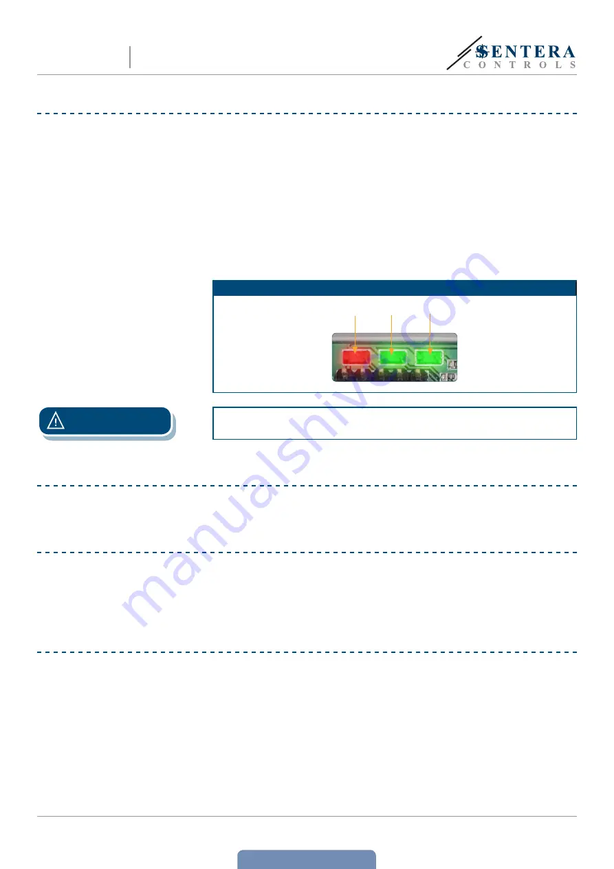
VERIFICATION OF THE INSTALLATION INSTRUCTIONS
■
Green LED1 indicates that the unit is supplied and that the Modbus RTU
communication with slave devices is active.
■
Green LED2 indicates active communication with the Internet. i.e. DIG-M
successfully communicates with the Sentera Web-Server sending parameters
to the Cloud.
■
Slowly blinking red LED3 indicates system error (connection to the Cloud has
been lost).
■
Fast blinking LED3 indicates that bootloader mode has been entered (see
Fig. 6
).
■
Blinking LEDs on the RJ45 sockets indicate that packages are transmitted via
Modbus RTU.
■
If this is not the case, check the connections.
Fig. 6 LED indications
LED 1
LED 3
LED 2
ATTENTION
The status of the LEDs can be checked only when the unit is energised. Take the
relevant safety measures!
TRANSPORT AND STORAGE
Avoid shocks and extreme conditions; stock in original packing.
WARRANTY AND RESTRICTIONS
Two years from the delivery date against defects in manufacturing. Any modifications
or alterations to the product after the date of publication relieve the manufacturer
of any responsibilities. The manufacturer bears no responsibility for any misprints or
mistakes in this data.
MAINTENANCE
In normal conditions this product is maintenance-free. If soiled, clean with a dry or
damp cloth. In case of heavy pollution, clean with a non-aggressive product. In these
circumstances the unit should be disconnected from the supply. Pay attention that
no fluids enter the unit. Only reconnect it to the supply when it is completely dry.
DIN RAIL MOUNTED SENTERA
INTERNET GATEWAY
DIG-M