

ENG
OPERATING MANUAL
DOOR / WINDOW SENSOR
ZC-100
The Sentek Door / Window Sensor is a wireless, battery powered,
Z-Wave compatible reed sensor. Each time its two parts, i.e. the
sensor's body and a magnet separate, a radio signal is sent. In
addition the Sentek Door / Window Sensor supports one DS18B20
temperature sensor and has one potential free input.
The Sentek Door / Window Sensor is designed for use with scenes in
home automation systems, alarm and surveillance systems and
everywhere else where information related to opening / closing of
doors, windows, garage gates, etc. is needed.
Technical data:
Power supply
Inputs
Supported temperature
sensors
Operating temperature
Radio protocol
Radio frequency
Range
Dimensions (L x W x H)
single ER14335 (1/2AA) 3,6V
battery
single, potential-free
single, DS18B20
0 - 40 °C
Z-Wave
868,4 MHz EU;
908,4 MHz US;
921,4 MHz AU/NZ;
869,2 MHz RU;
up to 30m indoors, depending on
building materials used and the
building structure
76 x 17 x 19 mm
Technical information:
•
Controlled via. any Z-Wave compatible controller.
•
Door/window opening detected through Sensor's body and a
magnet separation,
•
Quick installation - easily mounted on doors, windows, garage
gates, roller blinds, using double sided adhesive tape or screws,
•
Compatible with DS18B20 temperature sensors,
•
When connecting DS18B20 use single wire lead, no longer than 20
meters.
•
May be connected to a switch via potential-free IN input.
I General Information on the Sentek Sensor:
HINT
Connections should be made specifically
according to the diagrams presented in this
manual. Incorrect connections may be hazardous
or lead to device damage.
i
ZC-100 is a sensor that does not require any additional conductors;
it is based on the Z-Wave technology. Sentek offers a wide array of
advantages in comparison to other, similar systems. In general,
radio-based systems establish a direct connection between the
receiver and the transmitter. The radio signal is attenuated by every
obstacle along its path (in the household e.g. walls, furniture, etc).
In the worst case the radio system ceases to function.
II Sensor Installation:
1.Connect Sentek Door/Window Sensor according to the
appropriate diagram (if necessary)
2. Place battery inside the Sensor's casing,
3. Include into the Z-Wave network.
4. Install Sentek Door/Window Sensor observing diagram 4,
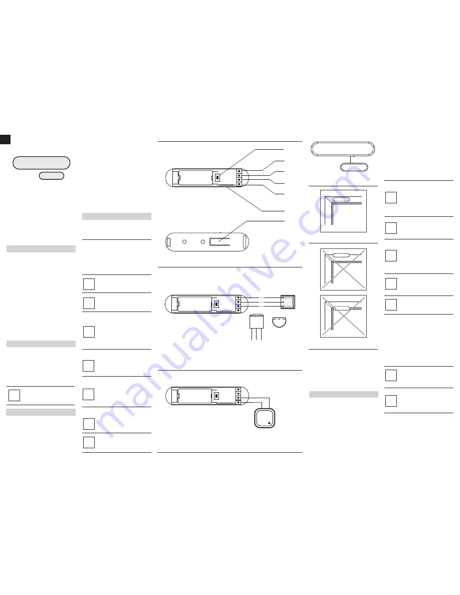
EXPLANATION OF CONDUCTOR MARKINGS:
TMP
- Tamper button. Detects removal, tampering etc. Used also
as a service button, to include/exclude the device to/from the
Z-Wave network,
IN
- Potential-free input,
TP – (TEMP_POWER)
- Power out for DS18B20 temperature
sensor,
TD – (TEMP_DATA)
- Signal terminal for DS18B20 temperature
sensor,
GND – (GROUND)
- Ground terminal.
GLOSSARY OF TERMS:
• INCLUSION -
the device sends out a Node Info frame, which
makes it possible to add it to Z-Wave network.
• EXCLUSION -
remove the device from Z-Wave network.
• ASSOCIATION -
controlling other devices included in Z-Wave
network.
3. Controlling the zZC-100 Door/Window Sensor with
Z-Wave network Controller
The Door/Window Sensor is a multifunctional device. This means
that it is equipped with an independent input circuit and a 1-wire bus
allowing it to be connected to a DS18B20 temperature sensor. As a
result, each device is represented by an independent icon in the
Z-Wave System.
2. Resetting the zZC-100 Door/Window Sensor
There is one way to reset the ZC-100 Door/Window Sensor. The
procedure cleans its EPROM memory, including the main controller
and Z-Wave network data.
To reset the Sentek Door/Window Sensor please follow below
instructions:
1)
Pressed the TMP button more than 5 seconds.
2)
Led start blinking.
3)
Release the TMP button.
4)
Reset is performed.
III Sensor Start-up
1.Installation of the Door/Window Sensor
STEP 1
Install the device observing the Figure 4 for correct positioning of
the Sensor and the magnet. Close the Sensor's casing.
[Inclusion/Exclusion] of the ZC-100 Door/Window Sensor [to/from]
the Z-Wave network.
STEP 2
The ZC-100 must be in range of the Z-Wave controller,
because the procedure of inclusion to the Z-Wave network
requires direct communication with the controller.
STEP 3
Locate TMP button, which allows for proper inclusion of device.
The ZC-100 Door/Window Sensor has a one,
potential-free IN input. IN input status may be
modified through the Sensor itself or by sending
GND signal to IN (diagram 3). If the Door/Window
Sensor will be used only as a binary sensor, do not
install the magnet.
i
USING IN INPUT:
Diagram 1 - General
Diagram 2 - Connection to DS18B20 sensor
Diagram 3 - Example connection - momentary switch
Sentek is a bidirectional wireless system. This means the signal is
not only sent to the receivers, but also the receivers send feedback
confirming the reception of the signal. This also confirms the
condition of receivers, which allows us to check whether or not a
device has actually been switched on. The safety of transmission of
the ZC-100 is comparable with a wire-linked bus system. The
ZC-100 operates in the free band for data transmission. The
frequency depends on the radio regulations in each individual
country.
Each Z-Wave network has its own unique network identification
number (home ID), which is why two or more independent systems
may be installed in a single building without any interference.
Although the Z-Wave technology is fairly new, it has already been
accepted as an official standard, just like Wi-Fi. Numerous
manufacturers from various fields offer solutions based on Z-Wave
technology, compatible with one another. This makes the system fit
for the future and allows for further development.
Sentek establishes a dynamic network structure. From the moment
of start-up, the location data of respective devices of the Sentek
System is updated automatically, in real time, by confirming their
condition in the working mesh network.
The DS18B20 temperature sensor may be installed
anywhere where very precise temperature readouts
are necessary. If adequately protected, the
DS18B20 sensor may be installed in humid
conditions, under water, sealed in concrete or placed
under the floor.
i
USING DS18B20 TEMPERATURE SENSOR:
Metal surfaces in close vicinity (e.g. metal switch
boxes, metal door trims) may impair the reception
capability!
i
The antenna should be placed above the battery.
Never cut, shorten or bend the antenna. Its length is
suited ideally to the band at which the system
functions.
i
NOTE!
Every time any changes are made to the
configuration of TP and TD lines (1-wire), i.e. when
DS18B20 sensor is connected/disconnected, it is
necessary to execute the procedure of exclusion
and repeated inclusion of the sensor module to the
Z-Wave network. The system will enter into the
learning mode only after connected DS18B20
sensor has been detected (about 10 s).
i
NOTE!
Do not connect sensors other than DS18B20 to the
1-wire line (TP and TD terminals).
i
NOTE!
It is prohibited to connect the TP and TD lines to
devices not compatible with the 1-wire protocol.
i
NOTE!
Resetting the device memory doesn't remove it
from the Z-Wave network's main controller
memory. To be able to re-include the device into the
Z-Wave network please exclude it first. Exclusion
may be performed either before or after the reset
procedure.
i
TP (VDQ)
TD (DQ)
GND
IN
TMP
(TOP VIEW)
3
2
1
GND
TD (DQ)
TP
(VDQ)
DS18B20
3
2
1
(VIEW FROM BELOW)
(TOP VIEW)
IN
GND
BELL-PUSH
(TOP VIEW)
TMP
NOTE!
To ensure the most accurate position detecting
always install the magnet in relation to the Sensor's
body, as shown in diagram 4.
i
(BOTTOM VIEW )
TMP
Diagram 4 - Correct positioning of the Sensor
and the magnet
ANTENNA ARRANGEMENT INSTRUCTIONS:
Diagram 5 - Correct sensor installation
Diagram 6 - Incorrect sensor installation
max. 5 mm
STEP 4
Set the Z-Wave controller to the inclusion or exclusion mode
STEP 5
The ZC-100 Door/Window Sensor is added to (or deleted from) the
by quickly pressing the TMP button three times (the button is
located on the underside of the device, inside its casing).
STEP 6
Correct inclusion of the device to the network will be signalled by
the Z-Wave controller.
NOTE!
ZC-100 Door/Window Sensor has two TMP buttons
- inside and underside the casing.
During normal operation both TMP buttons must be
secure. Do not use the sensor with opened casing.
i
MAGNETIC
SENSOR
NOTE!
Door/Window Sensor is equipped with a built-in
LED. LED blinks each time Door/Window Sensor
changes its state. LED blinking 5 times = correct
inclusion and exclusion.
i
NOTE!
TMP button, located on the underside of the
device, has two functions:
1. sets a device into the learn mode (Include to /
Exclude from a Z-Wave network),
2. tamper button. After correct installation (fig. 5
and 6), removing the whole sensor from its location
or opening its casing may release the TMP button
and trigger an alarm. If the TMP is to serve as a
tamper button, association for II-nd association
group must be configured (optionally, use the
Parameter 13).
i
BATTERY USE:
The ZC-100 Door/Window Sensor's battery life is up
to 2 years, on default settings.
Current battery level is displayed in the Z-Wave
controller's configuration interface. If a battery icon
turns red, it means the battery needs replacement.
In order not to trigger an alarm when replacing the
battery, II-nd association group must be deleted
and the Sensor's configuration must be changed to
default, prior to the battery change.
i
DS18B20
GND
max 30m
TD (DQ)
TP (VDQ)
TMP
1
2
3
NOTE!
Use reset precedure only in the event that network
primary controller is missing or otherwise inoperable.
i


