background image

11

REAR PANEL ASSEMBLY

Locate the two rear, framed glass panels. Each 
is marked (LEFT or RIGHT). 

The inside edge to 

go to the center control panel will be flat. The 

outside end to connect to the frame work will 

have a 'T' end 

Facing the shower from the front, the panels fi t 
according to their label.

Now position the Central Tower Panel between the 
rear panels.

Align the holes on the rear panels to those in the 
tower and fi x in place with the screws provided.

Using 8 of the shorter screws, fi x through the rear 
glass panel fi xing holes into the central tower. DO 
this on both long sides of the tower.

NOTE: A bead of sealant can be run 

between the joining faces of the back 

panels and Center Tower to provide an 

extra level of water protection.

You should consider doing this on all 

panels with meeting faces then simply 

wipe off any excess so non will be 'on 

show'

Now both glass panels are fully inserted into the 
uprights you can tighten up the four corners of the 
silver framework which will not hold the glass in 
position.

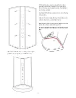
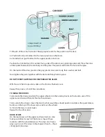
Next you need to fi t the Retaining Clips to hold the 
glass fi rmly. Position a clip tight up to the glass on 
the inside of the upper and lower rails, mark the 
position and drill a small hole then fi x a screw to 
hold the clip in place. Repeat top and bottom on 
both fi xed glass panels.

CAUTION WHEN DRILLING - ONLY DRILL 

THROUGH THE INNER SINGLE LAYER OF FRAME

Re-fi x the SEAL TRIM back on the inside of the 
lower curved frame.

GLASS RETAINING CLIPS

Summary of Contents for Pure Range

Page 1: ...TALLATION AND OPERATING MANUAL Technical Support 0871 526 5926 INSTALLERS PLEASE NOTE THESE INSTRUCTIONS ARE TO BE LEFT WITH THE CUSTOMER Pure Range Warranty Claims Or Delivery Damage www sensualspas co uk ...

Page 2: ......

Page 3: ... to have the shower installed by qualified fitters will invalidate your product guarantee Please ensure that all connections are water tight safe and insulated where applicable as the unit has connections that are made for transport purposes only and are not fully tightened Pack contents 1 x Tray base with pre fi fitted waste assembly 1 x Central tower panel with pre fi tt ed body jets 1 x Shower ...

Page 4: ...ion of your shower Please note that several parts may be pre fitted in place such as the monsoon shower head etc Please note the design and shape of parts may change occasionally but will always offer the same or greater functionality Hydro Shower Contents 1 2 3 5 6 8 9 4 7 ...

Page 5: ...ls and a pair of Magnetic door seals 7 Tower with and Body Jets and shower valve 8 Two Curved clear glass doors Two flat clear glass side pieces 9 Frame Uprights Two polished straight metal sections 10 Back Glass Panels Pair of glass with Polished Aluminium frames 11 8 Door stops short fi xingscr ews and cover caps 12 Two pairs of door handles 13 Hand Shower riser bar chrome hose and fixings 14 Ei...

Page 6: ...tub before fitting and ensure that your fitter fully tests the unit upon completion and attends to any leaks and faults before he leaves 5 All hoses such as to the valve assembly shower outputs and air switches and waste are fittedfor transport purposes and need to be properly sealed and tightened before use During transportation some connections can become dislodged and therefore break any watert...

Page 7: ...ts Gravity Fed systems If you have a Gravity fed system then fitting a Shower Pump will almost certainly be required Fitting a Shower pump rated over 1 5 bar is necessary as a minimum Shower pumps MUST be properly sited installed and commissioned Incorrectly installed shower pumps will cause adverse affects to your showering and bathing resulting in pulsing or starting and stopping of the pump If ...

Page 8: ...NCING ASSEMBLY OF THIS SHOWER YOU ACCEPT THAT THE PARTS HAVE ALL BEEN CHECKED AND ARE UNDAMAGED This product is fitted with toughened safety glass The glass is stronger than regular glass and if it breaks it will form small pieces of cubed glass not dangerous shards of glass These small pieces are still sharp so care must be taken to handle broken glass with care If the glass is put under stress o...

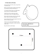
Page 9: ...preferred height Drill the holes in the central tower to the measurements shown in the diagram below Remove the three fixing nuts from the threaded ends on the rear of the seat fixing plate Pass the threads of the seat through the holes from the front of the tower panel At the rear pass the threads though the white support piece white plastic and then fasten the bolts to hold Ensure the bolts are ...

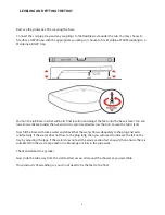
Page 10: ... with a spirit level laid across the tub ensure the tub is level Now fill the base with some water and check that the water flows adequately to the plug and exits satisfactorily If the water does not flow to the plug fully then you will need to increase the fall on the tray by adjusting the legs If the water does not exit the waste section fast enough then ensure there is suitable fall in the wast...

Page 11: ...the upper curved rail The screws pass through the holes in the side of the upright and fasten into the curved rail as shown in the digram below A power driver is advised for this process DO NOT FULLY TIGHTEN THE SCREWS ALLOW SOME MOVEMENT IN THE FRAME FOR INSTALLING THE FIXED GLASS Repeat the process on the other upright Finally join the lower curved rail to the other ends of the uprights using a ...

Page 12: ...nd fit over one long edge of the fixed glass panels Trim any excess leaving it running the full length Now position this glass panel up to the frame pushing the long edge of the glass into the upright of the frame until FULLY bedded into the frame upright This MUST be done from the inside of the frame The glass will sit within a lip on the inner surface of the curved rail both top and bottom DO NO...

Page 13: ...etween the joining faces of the back panels and Center Tower to provide an extra level of water protection You should consider doing this on all panels with meeting faces then simply wipe off any excess so non will be on show Now both glass panels are fully inserted into the uprights you can tighten up the four corners of the silver framework which will not hold the glass in position Next you need...

Page 14: ...ully lift the three joined sections onto the tray into position A bead of sealant along the tray where the panels will sit will provide a watertight barrier Remember to remove any excess sealant once the panels have been seated into position DO NOT SCREW THE PANELS TO THE TRAY JUST YET Above 8 x Short Screws used to join rear glass panels to tower panel viewed from rear ...

Page 15: ...wer tray and align the uprights with the rear glass panels so that the fixing holes line up From behind the side panel front edge locate a screw hole into the front frame screw through the lip of the white framework of the rear glass panels into the frame to secure in place 8 x short screws The help ease this process you may need to use the supplied drill bit in the holes to ensure they are wide e...

Page 16: ...f 8 twin wheel shower door runners cams There are two different types provided Continued Before You Fit The Doors You May Wish To See The SEALING THE SHOWER Section Of These Instructions And Apply Sealant Around The Base Of The Tray Prior To Fitting The Doors ...

Page 17: ...DO NOT OVER TIGHTEN AS YOU MAY BREAK THE GLASS With the cam fixed in position slide on the Chrome finished cover Repeat this process of all of the cam wheels TO HANG THE DOORS From inside the shower position the upper wheels into the running tracks on the inside curve of the upper curved rail and then let the door hand down From outside the shower move the door to what would be a closed position a...

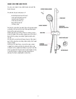
Page 18: ...wish to use some PTFE tape or other suitable products to provide the best water tight seal on this joint OVERHEAD SHOWER The overhead shower is comprised of three parts A chrome J shaped arm a Chrome finished overhead shower rose and a swivel joint The joint may be pre fitted to the shower rose The J Arm has two fixing points on the straight section that are threaded Remove the fixing nuts Positio...

Page 19: ...ss panel Fit the rear fixing nut from the rear of the shower to hold in place Secure the upper part of the riser bar with the screw provided Tighten both until secure Connect the silver hand shower hose to the lower part of the riser bar and the other end to the hand shower head At the rear of the shower locate the grey water supply hose coming from the shower valve and connect to the water inlet ...

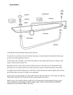
Page 20: ...silver caps and fit them over the ends of the washer and bolt to provide a clean finish The upper rail pushed over the glass from the front Using a flat head screwdriver tighten up the fixing point of the front rail which is located on the underside Position the two fixing brackets onto the inside of the rear panel of the shower in the holes provided Fix the brackets at the rear of the shower with...

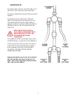
Page 21: ...wer riser bar water inlet When making the connections ensure they are water tight Check all pre fitted hoses as these may only be hand tight during manufacture The middle part of the valve handles the water on and off There are no connections to be made here The lower part of the valve has three connections to be made The HOT and COLD water supplies from you property connect to the outermost conne...

Page 22: ...PED The longer flapped seals fit onto the trailing edges of the doors The seals are not designed to touch the glass but when the doors are closed they meet so that water is unlikely to escape MAGNETIC The magnetic seals fit onto the doors where they meet Ensure all seals are fully fitted onto the glass especially the magnetic seals so that they form an even seal SHOWER SEALS ...

Page 23: ...p of higher specification can be fitted to supply multiple showers within the property When choosing a pump a twin impeller pump is recommended as this will ensure both the hot and cold water is of the same pressure You must seek further advise from a plumber to correctly spec the right shower pummp for your set up Always refer to the manufacturers instructions regarding shower pump installations ...

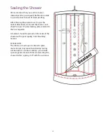
Page 24: ...test the shower and check for signs of water leaking please attend to them as required All sealant should be placed on the inside of the shower with a good quality Anti Moulding Sealant PLEASE NOTE The shower is made up of solid parts glass metal Acrylic Any leaks found during testing will be down to incorrect sealing you should spend a good amount of time water testing the shower before signing i...

Page 25: ... per minute flow and over 2 bar water pressure Water is pulsing If a pump has been used to supply water under pressure and the back jets or hand shower cause the pump to start and stop PULSING WATER remove the NON RETURN VALVES Remove the Braided hoses at the rear of the shower Look inside the valve where the hoses connected and you will see a silver coloured C clip Remove this and this will enabl...

Page 26: ... than 38 degrees simply press the knob on the dial in toward the main dial and then turn the dial past the 38 degree mark Turning the temperature dial past 30 degrees MUST be done with care to prevent scaling Safety Precautions On models fitted with Steam functions it is normal for the steam generator to get quite hot during use Please allow up to half an hour for the generator to cool before touc...

Page 27: ...opriate to the materials in the shower Not all general bathroom cleaners are designed for use on some materials of this product Harse abrashive cleaners containing bleach or peroxide MUST NOT be used DO NOT USE CIF OR OTHER ABRASIVE CLEANING PRODUCTS ON THIS SHOWER In hard water areas wash down the unit and remove the dirt periodically Fitting a water filtration device is also advisable in areas w...

Page 28: ...n the Cartridge Other reasons might be age of the Cartridge or even dirt or debris collecting in the Cartridge from the pipes BEFORE STARTING ENSURE THAT THE WATER SUPPLIES ARE DISCONNECTED OR ISOLATED It is imperative that the water supply to your shower in between 1 and 3 bar as exceeding this may damage the Thermostatic Cartridge From inside the shower on the lower of the three dials remove the...

Page 29: ...te down the position the ring is placed in Pull the plastic ring Temperature safety lock towards you to remove Keep this part safe You will now see the head of the Thermostat clearly visible Turn the head of the cartridge counter clockwise to remove To fit your new Thermostat simple reverse this process ...

Page 30: ...FOR TECHNICAL ASSISTANCE PLEASE CALL 0871 526 5926 ...

Page 31: ... Invoice No Install Date Install Information Water Supply Type Combi Mega Flow Pressurised Pumped Gravity Fed Cold Water Pressure LPM or BAR Hot Water Pressure LPM or BAR PEV or PRV fitted PEV PRV Details Details of pressure testing flow rate equipment used Plumbing Installation Installer Name Company Address Town City Post Code Contact Tel Credentials Certificates held Reg number Signature Date E...

Reviews: