System test procedure
Senstar LM100 Product Guide
Page 69
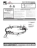
Linking relays to zones (local control mode)
The gateway’s outputs and the four relays on the ROC (OPT 1, OPT 2, OPT 3, OPT 4) can be
linked to the defined luminaire alarm zones. This provides up to 14 relays per gateway, for
signaling alarm conditions. If one relay is linked to more than one zone, the zones are OR’d for
alarm reporting.
1.
Under the Config tab, select the Zones sub-panel.
2.
Use the Zone: spin control arrows to select the zone to which a relay will be associated.
3.
Use the Relay: spin control arrows to select the relay which will be associated with the
specified Zone (the selected relay activates to signal an alarm in the zone).
4.
Repeat steps 1 and 2 until the defined alarm zones have associated relays, as required.
5.
Save the UCM configuration file and download the configuration changes to the gateway.
System test procedure
Once the system is setup and calibrated, conduct a series of tests to verify detection. Run a UCM
Response plot during the testing. Network based gateways can be tested over the network to
verify network communications.
•
Cut detection
- Use the tap test, or weave a piece of scrap fence wire tightly into the fabric of
the fence and cut the scrap wire. Test each zone in at least three separate locations.
At each location, tap the fence fabric, or cut the scrap wire, the number of times specified by
the Event Count par 1. Wait at least 2 seconds between taps.
PASS ____ FAIL____
Figure 60: Linking relays to zones
Note
The following tests can be used to verify gateway system operation.
The tests are described in a generic manner, which does not take into
account site specific details.
select the zone to which a relay
will be assigned
select the relay from the drop down menu