


Intelli-FLEX II processor settings
Intelli-FLEX II product guide • • • 5 - 47
Each Intelli-FLEX II processor requires approximately 1 W of power, making the
total power consumption of even large systems very small. A small UPS system
that is designed to run a personal computer system (typically 300 Watts) for 15 or
20 minutes will power an Intelli-FLEX II perimeter system for several hours.
Grounding
The earth ground connection must be stable and noise free. An improper or
unstable earth ground can induce noise in the Intelli-FLEX II processor.
Consult the local electrical code for grounding
requirements. AVOID sharp bends in the ground wire.
1. Follow the local electrical code, to install a low resistance ground rod at the
processor location.
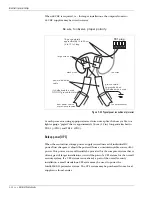
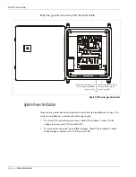
2. Using an appropriate ground wire, connect the ground rod to the ground
stud on the Intelli-FLEX II mounting plate.
Route the ground wire in through the cable entry port on the right side of the
enclosure, then along the bottom and up the side of the enclosure until you
reach the ground stud (see
Figure 5-46, Processor ground connection,
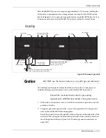
Figure 5-45 Placement of ground rod
Caution
DO NOT use the fence structure as an earth ground reference.
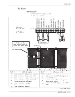
sensor cable
tie wrap
non-sensitive
feed cable
terminator
splice
ground rod (consult the local electrical
code for grounding requirements)
processor mounting height
1.2 to 1.8 m (4 to 6 ft.)
above ground level
Start point overlap
1.5 m (5 ft.)
processor
enclosure
terminator
Zone 2
Zone 1
splice
sensor cable


