UCM Calibration
FlexPI Product Guide
Page 29
UCM Calibration
UCM calibration overview
1.
Open the enclosure and set switch S5-4 to the OFF position (UCM calibration).
2.
Cycle the processor power OFF, then ON.
3.
Connect the UCM computer to T1 on the processor via USB.
4.
Start the UCM software.
5.
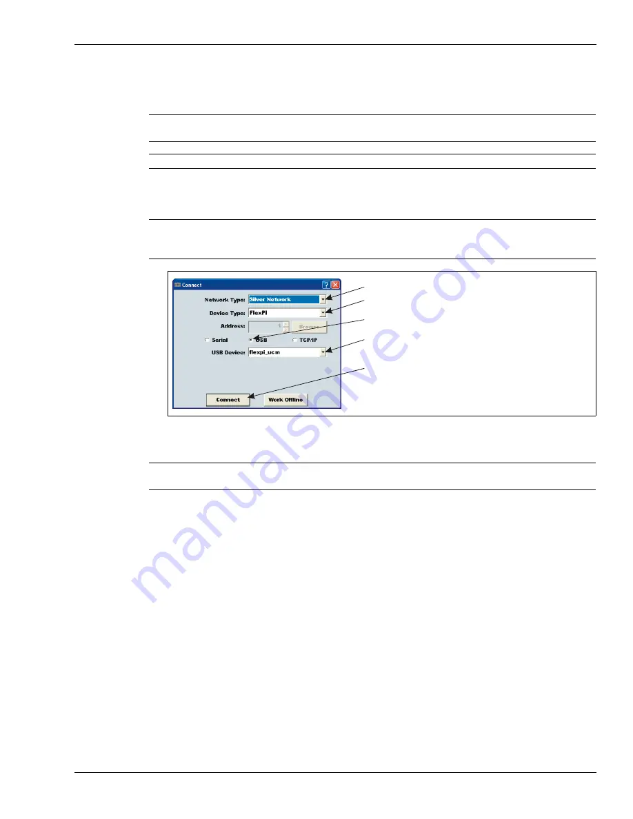
Select the connect button on the UCM Connect dialog.
The FlexPI UCM status window opens. The Status window provides information on the current
status of the processor and sensor cable.
FlexPI UCM calibration is done under the Cable Cfig tab. Select the Cable Cfig tab and the
Cable Configuration Window opens.
6.
Adjust the Filter Settings, set the Gain, and adjust the Cut Alarm and Climb Alarm detection
parameters.
7.
Save the UCM file and download the settings to the processor.
The Calibrate tool
Use the Calibrate tool to see the effects of Gain and Filter adjustments before changing the
processor’s settings. First, make the changes using the calibrate tool. Then, view a magnitude or
frequency response plot using the new settings while testing the installation. If the changes do not
result in the required level of detection, continue making and reviewing adjustments. When the
results are satisfactory, download the new parameters to the processor.
CAUTION
Some of the UCM parameters are available through the Advanced
parameters view and should be adjusted only by qualified personnel.
Note
Consult the online help for additional details on UCM operation.
Note
An enclosure tamper condition must exist to establish a UCM
connection to the FlexPI processor (enclosure cover - OFF, tamper
switch lever - UP, shunt not installed on T3, D17 DOOR LED - ON).
Figure 25: UCM Connect dialog
Note
Switch S5-4 must be set to OFF to operate the FlexPI processor with
UCM configuration settings.
Network Type = Silver Network
Device Type = FlexPI
connection = USB
USB Device = flexpi_ucm
select the Connect button to establish the connection


