


METIS M311 / M322 / H311 / H322 (17-pin)
SensorTools Software
34
Digital output
mode: Output of a switching signal:
- No function
: The output is deactivated (settings right beside have no function).
- Ready to use contact
: Device is ready and error free after self-test.
- Material contact
(only M3) for detecting whether a hot part is in the
measuring field: The limit switch contact is switching, when the beginning
of the temperature range is exceeded by 1% of the temperature range
span (the clear time of the peak
picker has to be set to ≥1 s or to Auto).
- Limit switch contact:
if a certain temperature is exceeded or falling be-
low a threshold.
- Signal strength contact
: Signal strength too low (for use as dirty win-
dow alarm: identifies the degree of contamination of the optics or a win-
dow or detects interferences (dust ...) in the beam path and trigger an
alarm if activated).
- Device temperature
: When exceeding the maximum internal device
temperature.
For PID controller:
- Setpoint limit 1 / setpoint limit 2
: The setpoint limit is a limit temperature above or below the set-
point temperature that should not exceeded or to be below. Two setpoints can be defined. The
output is activated if the measured value exceeds the defined setpoint value. The output is also ac-
tivated if the measured value falls below the defined value. Entry of the setpoint value has to be
done relative to the setpoint, positive or negative, e.g.
20°C if the setpoint value is 800°C and the output should
be active at 820°C. Values will be entered in the PID con-
troller form (see
- Setpoint band
: The setpoint band is composed of the 2
setpoint limits and defines a range within the temperature
has to be. The output is activated if the measured value is outside the defined value.
- Controller active
: Output is active when the controller is active.
- Successful control
: Output is active when a control process is terminated (a possibly hold time
has elapsed).
Various settings:
- Switching value:
Activates the corresponding output at the set switching value (the LEDs 1-3 on
the unit indicate the activated state).
- Hysteresis:
The hysteresis is the value at how many degree below the limit value the output is
switched back.
- Logic:
The state of the digital outputs can be set:
-
NO
(normally open): outputs have in active state 24 volts to the pins and in inactive state 0 V
(output max. 100 mA,
load min. 300 Ω).
-
NC
(normally closed): outputs have in active state 0 volts to the pins and in inactive state 24 V
(output max. 100 mA, loa
d min. 300 Ω).
- Extended settings:
Depending on the selection are either available:
Time settings:
A verification time and a hold time can be set:
-
Verification time:
select “immediately” to activate the output function immediately when hap-
pening. A time between 1 and 65535 ms delays the activation accordingly.
- With the
hold time
, the output can be kept active longer than the original signal.
-
None:
signal is active as long as the function is active
-
Process start:
signal is active up to the next start (of a program or manual start)
-
Time value
(between 1 and 65534 ms): signal is active for the entered time.
- Reference temperature:
The 2-color temperature or the temperature of one channel can be used
to activate the output.
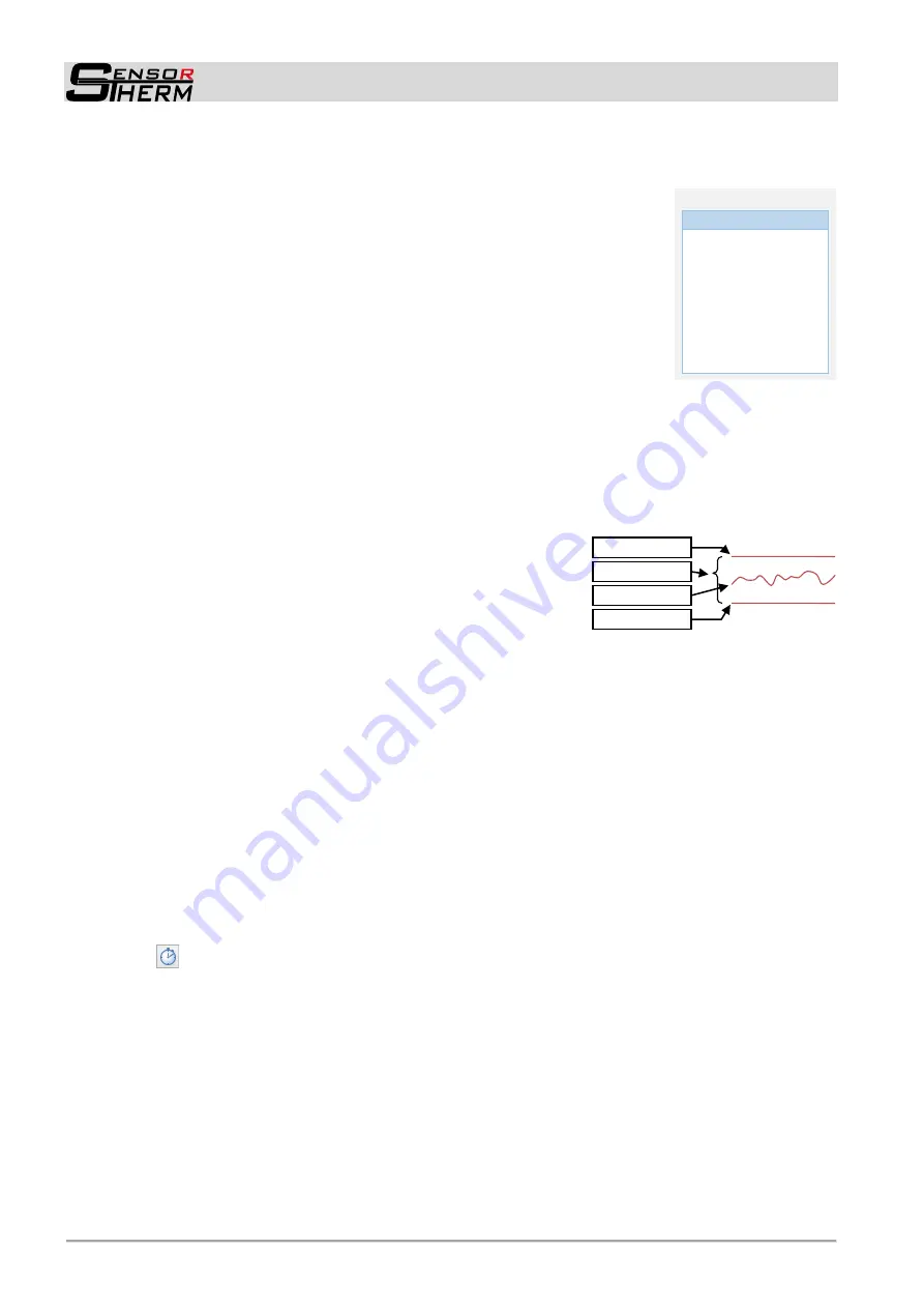
Example
Setpoint limit 1
Setpoint band
Setpoint limit 2
Measured value
No function
v
Function
Contact ready to use
Material contact
Limit switch contact
Signal strength
Device temperature
Setpoint limit 1
Setpoint limit 2
Setpoint band
Controller active
Successful control